Table of Contents
Advertisement
Quick Links
Test Equipment Depot - 800.517.8431 - 99 Washington Street Melrose, MA 02176 - TestEquipmentDepot.com
729/729 FC
Automatic Pressure Calibrator
Users Manual
May 2017
© 2017 Fluke Corporation. All rights reserved. Specifications are subject to change without notice.
All product names are trademarks of their respective companies.
Advertisement
Table of Contents

Related Manuals for Fluke 729


Summary of Contents for Fluke 729
- Page 1 Test Equipment Depot - 800.517.8431 - 99 Washington Street Melrose, MA 02176 - TestEquipmentDepot.com 729/729 FC Automatic Pressure Calibrator Users Manual May 2017 © 2017 Fluke Corporation. All rights reserved. Specifications are subject to change without notice. All product names are trademarks of their respective companies.
- Page 2 LIMITED WARRANTY AND LIMITATION OF LIABILITY This Fluke product will be free from defects in material and workmanship for three years from the date of purchase. This warranty does not cover fuses, disposable batteries, or damage from accident, neglect, misuse, alteration, contamination, or abnormal conditions of operation or handling.
-
Page 3: Table Of Contents
Buttons ........................... 10 The Display ........................13 Triple-Function Display ....................17 RTD Connection ......................18 Pressure Module Connection ..................18 Fluke Connect Device Connection ................19 Ports ..........................20 Download the Fluke Connect App ................22 Enable the Fluke Connect ... - Page 4 729/729 FC Users Manual Setup Menu ........................24 Manage FC Devices (729 FC Only) ................24 Locator ........................24 729 Information ......................25 729 Setup ......................... 26 Manage Users......................27 Manage Test Results ....................28 Manage Screen Shots ....................28 Manage Custom Tasks .....................
- Page 5 Contents (continued) Set Fixed mA Output .................... 47 Re-range Transmitter .................... 47 Device Diagnostics ....................47 Calibrate (Ad hoc) ...................... 47 Adjust ........................48 PV Zero Trim ......................48 mA Output Trim ....................48 Trim to Applied Values ..................49 As Left ........................
- Page 6 729/729 FC Users Manual In Case of Difficulty ....................64 Battery Replacement ....................65 Update Product Firmware ..................66 Calibration Data ......................66 Service Center Calibration or Repair ................ 66 Error Messages ......................67 HART Commands ..................... 73 Documenting Functionality ..................74 Strap ..........................
-
Page 7: Introduction
• Source and simulate milliamp signals while measuring pressure for testing current to pressure The Fluke 729 and 729 FC Automatic Pressure converters (I/P). Calibrators (the Product) are portable field pressure calibration tools for lab or field use. This battery-operated •... -
Page 8: Contact Fluke
Advanced features like auto step and auto ramp allow tests of devices automatically. • The pressure switch test automatically ramps pressure up and down across expected switch trip setting to calibrate pressure switches. • Fluke Connect (FC) built into FC models. -
Page 9: Safety
Automatic Pressure Calibrator Safety Safety • Do not touch voltages >30 V ac rms, 42 V ac peak, or 60 V dc. Warnings and Cautions • Do not use the Product if it is damaged. A Warning identifies conditions and procedures that are •... - Page 10 Examine the test leads for damaged near heat or fire. Do not put in sunlight. insulation, exposed metal, or if the wear • Use only Fluke approved power adapters indicator shows. Check test lead to charge the battery. continuity. •...
- Page 11 Automatic Pressure Calibrator Safety or vented immediately to prevent Product • Pressure sensors can be damaged and/or damage or possible personnel injury. Push personnel injury can occur due to to zero the pressure sensor when improper application of pressure. The vented to atmospheric pressure.
-
Page 12: Symbols
729/729FC Users Manual Symbols The symbols used in this manual and on the Product are in Table 1. Table 1. Symbols Symbol Description WARNING. RISK OF DANGER. WARNING. HAZARDOUS VOLTAGE. Risk of electric shock. Pressure Consult user documentation. - Page 13 This product contains a Lithium-ion battery. Do not mix with solid waste stream. Spent batteries should be disposed of by a qualified recycler or hazardous materials handler per local regulations. Contact your authorized Fluke Service Center for recycling information. China metrology certification mark for measuring instruments manufactured in the Peoples Republic of China (PRC).
-
Page 14: Standard Equipment
729/729FC Users Manual Standard Equipment Figure 1 and Table 2 show standard equipment. idj016.eps Figure 1. Standard Equipment... - Page 15 Automatic Pressure Calibrator Standard Equipment Table 2. Standard Equipment Equipment Equipment 729 and 729 FC Automatic Pressure Fitting, 1/8 in NPT-Female X M20-Female Calibrators AC/DC converter Fitting, 1/4 in BSP-Female X 1/8 in NPT-Female Mains line cable Hanger Kit Hose to drain condensed water generated from Rechargeable Li Ion Battery the Product.
-
Page 16: Buttons
729/729FC Users Manual Buttons See Figure 2 and Table 3 for the Product buttons and the softkeys. idj001.eps Figure 2. Buttons... - Page 17 Automatic Pressure Calibrator Buttons Table 3. Buttons Number Description Number Description Power button. Push to turn on or turn off Display brightness button. Push to change the the Product. display brightness from dim to bright and back again. BACK button. Push to move to the previous user interface (UI) screen.
- Page 18 729/729FC Users Manual fTable 3. Buttons (cont.) Number Description Number Description SOURCE PRESSURE button. Use this function to output (source) a target pressure from the VDC button. Push to select the measure dc Product. Use the arrows to select the Setpoint voltage function.
-
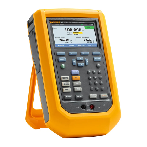
Page 19: The Display
Automatic Pressure Calibrator The Display The Display Figure 3 and Table 4 explain the display. idj014.eps Figure 3. The Display... - Page 20 Setpoint indicator temperature probe, process variable (PV) of connected HART device, or Fluke Connect secondary device reading. Fluke Connect on indicator (729 FC only) Softkey indicator HART on indicator Current, voltage, or pressure switch display 24 volt loop power active indicator...
- Page 21 Automatic Pressure Calibrator The Display The display can also show different configurations: Typically, the display does not show the third functions, see Figure 4. • The top screen for the internal pressure has these different functions: VENT SOURCE MEASURE • The bottom screen shows these different functions: Measure Current Source Current...
- Page 22 729/729FC Users Manual The screen has two sections: The upper display shows the internal pressure controller The lower display shows the electrical status and includes: status and includes: • Mode: Measure Current, Source Current, Simulate • Mode: Measure, Source, and Vent Current, Measure V dc, and Switch.
-
Page 23: Triple-Function Display
Automatic Pressure Calibrator The Display Triple-Function Display When the third function (RTD, External Pressure Module, HART Transmitter, or FC secondary device) is connected, the Product changes to triple-function display automatically. In the subsequent triple-function display, the original bottom half of the display is divided into two parts: •... -
Page 24: Rtd Connection
729/729FC Users Manual RTD Connection The display can show RTD temperature measurements in the selected unit (C/F) as the third-function. When the temperature unit field highlights, push the softkey to toggle the temperature setting. The ohms reading shows. Note The Product supports PT100-385 RTD only. -
Page 25: Fluke Connect Device Connection
Automatic Pressure Calibrator The Display Fluke Connect Device Connection The display shows connected FC device measurements as the third-function. See Setup Menu for information to manage secondary FC devices. -
Page 26: Ports
729/729FC Users Manual Ports Figure 7 and Table 5 show the Product ports. idj013.eps Figure 7. Product Ports... - Page 27 Automatic Pressure Calibrator Ports Table 5. Product Ports Number Description Battery charger/universal power supply port. Use the battery charger for bench-top applications that have ac line power available. Use the battery charger to charge the battery while installed in the Product. USB port –...
-
Page 28: Download The Fluke Connect App
729/729FC Users Manual Download the Fluke Connect To download the Fluke Connect App, see Figure 8. idj025.eps Figure 8. Download the Fluke Connect App... -
Page 29: Enable The Fluke Connect App
Automatic Pressure Calibrator Enable the Fluke Connect App Enable the Fluke Connect To enable the Fluke Connect App on your phone, see Figure 9. idj027.eps Figure 9. Enable the Fluke Connect App... -
Page 30: Setup Menu
1234. Enter the Setup menu. To access the Setup menu, push . Push (Manage FC Device) to set 729 FC as The Setup menu includes submenus for Product the primary device and discover other units that have configuration. The submenus are: Fluke Connect. -
Page 31: 729 Information
Setup Menu 729 Information There are also softkeys at the bottom of this screen. These are: The 729 Information submenu is an information-only screen that shows information about the Product. The • - Calibrate Pressure – Follow the prompts... -
Page 32: 729 Setup
729/729FC Users Manual 729 Setup Table 6. 729 Setup Menu (cont.) The 729 Setup submenu shows the information in Table 6. Menu Parameter Function Table 6. 729 Setup Menu Set the format of the date. Use the Date Format softkeys to select yyyy-mm-dd,... -
Page 33: Manage Users
Automatic Pressure Calibrator Setup Menu Manage Users Table 6. 729 Setup Menu (cont.) The Manage Users submenu controls access to add or Menu Parameter Function delete Product user names from this menu. The Product has a programmable Auto Battery Timeout feature to •... -
Page 34: Manage Test Results
729/729FC Users Manual Manage Test Results Manage Screen Shots The Product saves test results as found and as left and The Product can take screen shots of any screen and saves calibration results. store them. In the Setup menu, push the arrow buttons to To take a screen shot: highlight Manage Test Results. -
Page 35: Manage Custom Tasks
Automatic Pressure Calibrator Setup Menu Manage Custom Tasks Drain Water (Condensation) Use this submenu to delete custom tasks (see Tasks To drain condensation from the Product, see Figure 10: Menu). To delete a single task, use the arrow to select a Connect the hose to collect drained water. - Page 36 729/729FC Users Manual idj030.eps Figure 10. Drain Water from Product...
-
Page 37: Keypad Test
Automatic Pressure Calibrator Tasks Menu Keypad Test Tasks Menu Use this screen to check the Product buttons. Push any Tasks let you set up calibration and measurement tasks button and verify the onscreen response. to save and recall for later use. For the power button, push and hold for 2 seconds. -
Page 38: Pressure Transmitter (P/I)
729/729FC Users Manual From this second screen, use the arrows, numeric Pressure Transmitter (P/I) keypad, and to change the values of the Use this function to calibrate a P/I transmitter (pressure to Tolerance of Range, Test Strategy, Auto Settling current) with current measurement. - Page 39 Automatic Pressure Calibrator Tasks Menu idj005f.eps Figure 11. Pressure Transmitter (P/I) Task Connections...
-
Page 40: Pressure Switch (Sw)
729/729FC Users Manual Once you enter the parameters, push Pressure Switch (SW) (Continue). Use this feature to calibrate a pressure switch. See Figure 12 for connections: Push (Auto Test) or (Manual Test) to do the As Found switch test. The test runs. - Page 41 Automatic Pressure Calibrator Tasks Menu idj008.eps Figure 12. Switch Test Connections...
-
Page 42: Current To Pressure Test (I/P)
729/729FC Users Manual Tolerance of Range, Test Strategy, and Auto Settling Current to Pressure Test (I/P) Time can be set from here. Use this feature to calibrate a current to pressure (I/P) converter with current source and pressure To save these settings as a customized task, push measurements. - Page 43 Automatic Pressure Calibrator Tasks Menu idj009.eps Figure 13. Current to Pressure Test (I/P) with External Pressure Module...
- Page 44 729/729FC Users Manual idj009a.eps Figure 14. Current to Pressure Test (I/P) with Internal Connections...
-
Page 45: Pressure Leak Test
Automatic Pressure Calibrator Tasks Menu Note Pressure Leak Test Make sure to push after EACH value change. Use this feature to test a pressure device for leaks. For connections, see Figure 15: Push (Continue). When the pressure leak test completes, the Product shows the results. -
Page 46: Pressure Transmitter (P/V)
729/729FC Users Manual Pressure Transmitter (P/P) Pressure Transmitter (P/V) To calibrate a pressure-to-pressure transmitter, use this Use this feature to calibrate a pressure to voltage feature. This feature requires a pressure module to transmitter with voltage measurement. For connections, see measure pressure output from a connected transmitter. - Page 47 Automatic Pressure Calibrator Tasks Menu idj026.eps Figure 15. Pressure Transmitter (P/P) Connections...
-
Page 48: Hart Functionality
729/729FC Users Manual • Perform service features including: HART Functionality PV Zero Trim The Product interfaces with HART devices. It can: mA Output Trim • View and modify transmitter setup and data that includes: Trim to Applied Values Write Lower Range Value (LRV) -
Page 49: Loop Power +24V On
Automatic Pressure Calibrator HART Functionality Loop Power +24V ON Push and the Product searches (polls) the bus to find any connected HART devices. From this screen, there are The Product supplies loop power at 24 V dc to a current these softkeys: transmitter disconnected from the system. - Page 50 729/729FC Users Manual idj029.eps Figure 16. Connection with Loop Power Enabled...
-
Page 51: Enable Hart 250Ω
Automatic Pressure Calibrator HART Menu HART Data Ω Enable HART 250 The HART data screen shows information about the The Product has a selectable 250 Ω HART resistor to connected HART device. Push (Page Up) or facilitate use with HART devices. Enable the HART resistor (Page Down) where necessary. -
Page 52: Hart Service
729/729FC Users Manual HART Service mA Output Trim HART Service includes these submenus: In the mA output trim screen, you can adjust the transmitter output. • PV Zero Trim Start with the 4 mA range. Push (Fetch) to get •... -
Page 53: Set Fixed Ma Output
Automatic Pressure Calibrator HART Menu Set Fixed mA Output Device Diagnostics Enter the necessary mA value to output from the connected Select Device Diagnostics to send the self-diagnostics transmitter. command to the connected transmitter and view the transmitter Self Test result. •... -
Page 54: Adjust
729/729FC Users Manual And these softkeys are active: Adjust Push (HART Adjust). These choices are shown: – Linear/Square Root Selection • PV Zero Trim – Save as Customized mA Output Trim • – Leak Test •... -
Page 55: Trim To Applied Values
Automatic Pressure Calibrator Measure Mode Bus Polling Trim to Applied Values Enter the LRV pressure value necessary in the Setpoint Bus Polling goes back into the bus polling screen and scans entry and let the pressure settle. for connected HART devices. Push ... -
Page 56: Current Measurement
729/729FC Users Manual Current Measurement Volts Measurement The Product measures 0 mA to 24 mA. The Product measures 0 V dc to 30 V dc. Figure 17 shows measurement connections for voltage measurements. Move the cursor to highlight Measure Current. Push ... -
Page 57: Pressure Measurement
Automatic Pressure Calibrator Measure Mode Pressure Measurement The Product supports the 700P and 750P series pressure modules. See Accessories. Before you use a pressure module, read its instruction sheet. The modules are different in how they are used, zeroed, what types of process pressure media are allowed, and accuracy specifications. - Page 58 729/729FC Users Manual Connect a pressure module to the Product as shown in Caution Figure 19. The pressure module shows on the display after To prevent possible damage to the Product or several seconds once installed. to equipment under test: The Product automatically senses the pressure module Never apply more than 10 lb-ft.
- Page 59 Automatic Pressure Calibrator Measure Mode Idj010..eps Figure 19. Pressure Module Connections...
-
Page 60: Autostep And Auto Ramp The Output Value
729/729FC Users Manual Select the Repeat Mode: Autostep and Auto Ramp the Output Value • (One Time) Autostep and Auto Ramp can automatically adjust the value of source functions for pressure or current. • (Repetitive) Autostep Select the Step Style: To configure the Product to make a sequence of steps that •... -
Page 61: Auto Ramp The Output
Automatic Pressure Calibrator Measure Mode Auto Ramp the Output While the signal ramps, the output adjusts to the value. The selection of endpoints and ramp time determines the size of When ramped, the source sweeps up or down in value. Use steps. -
Page 62: Temperature Measurement
See Figure 20. Note The factory default type is PT100-385 so if the Product is used with the Fluke 720 RTD Probe (PN 4366669), it is not necessary to set the probe type. Connect the probe to the Product and configure the display to read temperature. -
Page 63: Source Ma Mode
Automatic Pressure Calibrator Measure Mode Source mA Mode To turn off sourcing completely, select another function. The operation mode (for example, measure or source) Note shows on the display. If the Product is not in mA source Use the source current function to drive a current mode, push . - Page 64 729/729FC Users Manual idj011.eps Figure 21. Connections to Simulate a 4 to 20 mA Transmitter...
-
Page 65: Log
Choose the Log Source from any of the available upload test results to a PC from the Product. A PC, measured values with , , or . Microsoft Windows, USB cable (supplied), and Fluke The log source can be internal pressure, external ... - Page 66 729/729FC Users Manual idj006f.eps Figure 22. Connection to a PC...
-
Page 67: The Battery
Automatic Pressure Calibrator The Battery The battery charge indicator (top-right of display) shows The Battery while the battery is outside of the Product. Solid green The Product features a rechargeable battery. Charge the bars show the level of charge on the battery. When all battery while it is inside or outside of the Product. -
Page 68: Maintenance
729/729FC Users Manual Maintenance Clean the Product Clean the Product and pressure modules with a soft cloth Warning dampened with water or water and mild detergent. To prevent possible electrical shock, fire, or Caution personal injury: To prevent possible damage to the Product, •... - Page 69 Automatic Pressure Calibrator Maintenance Inspect the springs for wear or loss of tension. They should be approximately 3.8 mm (0.15 in) long in the relaxed state. If they are shorter, the O-ring will not seat properly. Replace if necessary. Clean and inspect all parts and then reinstall the O- ring and spring assemblies into the valve body.
-
Page 70: In Case Of Difficulty
To prevent possible electrical shock, fire, or illuminated, but the Product does not turn on, have the personal injury, do not use the Product if it Product serviced. See Contact Fluke. operates abnormally. Protection may be impaired. When in doubt, have the Product... -
Page 71: Battery Replacement
Contact Fluke and User-Replaceable Parts. Note Take spent batteries to a qualified recycler or hazardous materials handler for disposal. Contact an authorized Fluke Service Center for recycling information. To replace the battery, see Figure 24: Push and select Maintenance. -
Page 72: Update Product Firmware
Be sure to pack the Product Search for “729”. securely, in the original shipping container if it is On the results page, select the Software available. See Contact Fluke and the Warranty Downloads tab. Statement. Click on the necessary software link. -
Page 73: Error Messages
Automatic Pressure Calibrator Maintenance Error Messages problem with the configuration of the Product or test. See Table 8 to troubleshoot these issue. The Product display shows error messages when the Product fails to meet certain conditions or there is a Table 8. - Page 74 729/729FC Users Manual Table 8. Error Messages (cont.) Error Message Explanation Potential Root Cause Failed to load filesystem from flash memory Data flash memory failure, the main PCA Filesystem fatal error when startup. needs service. Not enough space, delete some files and Cannot save screen Failed to save screen into filesystem.
- Page 75 Automatic Pressure Calibrator Maintenance Table 8. Error Messages (cont.) Error Message Explanation Potential Root Cause PCM pressure exceeds limit The pressure of PCM exceeds its limit. Vent pressure and do the task again. 1. Clear all files and try again. Failed to initial memory lists for Failed to initial DPC memory 2.
- Page 76 Lost connection to FC devices, Running task aborted, due to lost connection sure FC is active. Redo the discovery Task aborted to Fluke Connect secondary unit. process. After connected, run the task again. Lost connection to RTD, Task Running task aborted because RTD was...
- Page 77 Automatic Pressure Calibrator Maintenance Table 8. Error Messages (cont.) Error Message Explanation Potential Root Cause Make sure input signal is in the range of Input Out Of Range Invalid input signal when calibrating. the current calibration point, and try again. Invalid EMM/PCM CAL Checksum failed for calibration constant, constant, Factory value...
- Page 78 729/729FC Users Manual Table 8. Error Messages (cont.) Error Message Explanation Potential Root Cause 1. The pressure volume is too large, reduce the volume and try again. 2. The leakage of pressure volume is too large. Test the leakage and try again.
-
Page 79: Hart Commands
Automatic Pressure Calibrator Maintenance HART Commands Number Command Description Type See Table 9 for Product HART commands. Read Long Tag Universal Table 9. Supported HART Commands Number Type Read Unique Identifier Universal Command Description Read Primary Variable Universal Write Primary Variable Range Common Value Practice... -
Page 80: Documenting Functionality
729/729FC Users Manual Strap Documenting Functionality Attach the Product carrying strap as shown in Figure 25. The Product uses calibration management software to Adjust the straps as necessary to hang the Product on communicate with documenting software. The Product any sturdy support. - Page 81 Automatic Pressure Calibrator idj012.eps Figure 25. Product Strap...
-
Page 82: Hanger Accessory
729/729FC Users Manual Hanger Accessory Figure 26 shows the provided magnetic hanger accessory. idj018.eps Figure 26. Hanger Accessory... -
Page 83: User-Replaceable Parts And Accessories
User-Replaceable Parts and Accessories Table 10 lists replacement parts and accessories. Table 10. User-Replaceable Parts and Accessories Item No. Description Quantity Fluke P/N BP729, Rechargeable Li Ion Battery 4817068 Power Charger, AC/DC 4878453 Mains Adapters International (Except For China) 2441372... - Page 84 729/729FC Users Manual Table 10. User-Replaceable Parts and Accessories (cont.) Item No. Description Quantity Fluke P/N Hose, Nylon 3.3 Ft 4366602 Fitting, 1/8" NPT-Female X 1/4" NPT-Female 4366616 Fitting, 1/8" Tube x 1/8" NPT-Male 4551693 Fitting, 1/8" NPT-Female x M20-Female 4366633 Fitting, 1/4"...
-
Page 85: Specifications
Automatic Pressure Calibrator Specifications Specifications Pressure Specification 1-year Specification ..............0.02 % of full scale Control Specification .............. 0.005 % full scale minimum Temperature Compensation ........... 15 °C to 35 °C (59 °F to 95 °F) to rated accuracy Note: For temperatures from -10 °C to 15 °C and 35 °C to 50 °C, add 0.04 % of full scale Electrical Specification All specifications are valid to 110 % of range, except 24 mA source and simulate which are valid to 100 % of range. - Page 86 729/729FC Users Manual Loop Compliance Voltage ............24 V dc @ 20 mA mA Simulate External Voltage Requirement ......12 V dc to 30 V dc Temperature Measurement Only/100 Ω Pt(385) RTD .... -50 °C to +150 °C (-58 °F to +302 °F) Temperature Resolution ............
-
Page 87: Product Models
-82.73 kPa to 729 300G +300.000 psi +20.6843 bar +2068.43 kPa -12.0000 psi to -0.82737 bar to -82.737 kPa to 729 30G FC +30.0000 psi +2.06842 bar +206.843 kPa -12.000 psi to -0.8273 bar to -82.73 kPa to Wireless communication for 729 150G FC +150.000 psi... - Page 88 +30.0000 psi +2.06842 bar +206.843 kPa For China, wireless -12.000 psi to -0.8273 bar to -82.73 kPa to 729CN 1M FC communication for Fluke +150.000 psi +10.3421 bar +1034.21 kPa Connect -12.000 psi to -0.8273 bar to -82.73 kPa to 729CN 2M FC +300.000 psi...
- Page 89 For Japan, 2 MPa range, no 729JP 2M +2068.43 kPa wireless communication -82.737 kPa to 729JP 200K FC +206.843 kPa For Japan, wireless -82.73 kPa to 729JP 1M FC communication for Fluke +1034.21 kPa Connect 729JP 2M FC -82.73 kPa to +2068.43 kPa...
-
Page 90: Mechanical Specification
729/729FC Users Manual Mechanical Specification Size (H x W x L) ..............7.0 cm x 27.9 cm x 17.3 cm (2.75 in x 11.0 in x 6.8 in) Weight ..................2.95 kg (6.5 lb) Environmental Specification Operating Temperature ............-10 °C to +50 °C for measurement, 0 °C to 50 °C for pressure control Battery will only charge from 0 °C to 40 °C... - Page 91 Automatic Pressure Calibrator Specifications Electromagnetic Compatibility (EMC) International ..........IEC 61326-1: Basic Electromagnetic Environment; CISPR 11: Group 1, Class A Group 1: Equipment has intentionally generated and/or uses conductively- coupled radio frequency energy that is necessary for the internal function of the equipment itself.
- Page 92 729/729FC Users Manual...
Need help?
Do you have a question about the 729 and is the answer not in the manual?
Questions and answers