Table of Contents

Related Manuals for Fluke 729 Pro


Summary of Contents for Fluke 729 Pro
- Page 1 729 Pro Automatic Pressure Calibrator Users Manual October 2020 © 2020 Fluke Corporation. All rights reserved. Specifications are subject to change without notice. All product names are trademarks of their respective companies.
- Page 2 Fluke authorized resellers shall extend this warranty on new and unused products to end-user customers only but have no authority to extend a greater or different warranty on behalf of Fluke. Warranty support is available only if product is purchased through a Fluke authorized sales outlet or Buyer has paid the applicable international price.
-
Page 3: Table Of Contents
Triple-Function Display ............... RTD Connection ................. Pressure Module Connection ............. 10 Ports......................11 Setup Menu....................12 729 Pro Information ................13 729 Pro Setup..................14 Manage Users ..................15 Manage Test Results................15 Manage Screen Shots ................ 16 Manage Custom Tasks............... 16 Maintenance Menu ................ - Page 4 729 PRO 729 PRO Users Manual Users Manual HART Menu....................27 HART Data..................27 HART Service ..................27 PV Zero Trim ................28 mA Output Trim ................28 Trim to Applied Values ..............28 Set Fixed mA Output ..............28 Re-range Transmitter ..............
- Page 5 Automatic Pressure Calibrator Table of Contents User-Replaceable Parts and Accessories..........48 Specifications .................... 49 Pressure Specification ................ 49 Electrical Specification................ 49 Pressure Measurement Module Specification ........50 Mechanical Specification ..............50 Environmental Specification ............... 50 Safety ....................50 Electromagnetic Compatibility (EMC) ..........51...
- Page 6 729 PRO 729 PRO Users Manual Users Manual...
-
Page 7: Introduction
Introduction The Fluke 729 Pro Automatic Pressure Calibrators (the Product) are portable field pressure calibration tools for lab or field use. This battery-operated product performs automatic pressure calibration of transmitters, pressure switches, and gauges. The automatic functions are done by the Product or by downloaded tasks from calibration- ®... -
Page 8: Contact Fluke
729 Pro Users Manual Contact Fluke Fluke Corporation operates worldwide. For local contact information, go to our website: www.fluke.com. To register your product, view, print, or download the latest manual or manual supplement, go to our website. Fluke Corporation P.O. Box 9090... - Page 9 Table 1. Standard Equipment Item Description Item Description Fitting, 1/8 in NPT-Female x 1/4 in 729 Pro Automatic Pressure Calibrator NPT-Female AC/DC converter Fitting, 1/8 in NPT-Male x G1/4-Male Fitting, 1/8 in NPT-Female x ...
-
Page 10: Buttons
729 Pro Users Manual Buttons Table is a list of the Product buttons and the softkeys. Table 2. Buttons Item Description Push to turn on or turn off the Product. Push to move to the previous user interface (UI) screen. When navigating through the ... - Page 11 Automatic Pressure Calibrator Buttons Table 2. Buttons (cont.) Item Description Push to enter the Setup menu to change operating parameters. See Setup Menu. Push to enter the Tasks menu. See Tasks Menu. Push to release pressure at the internal pressure port. VENTING shows on the display ...
-
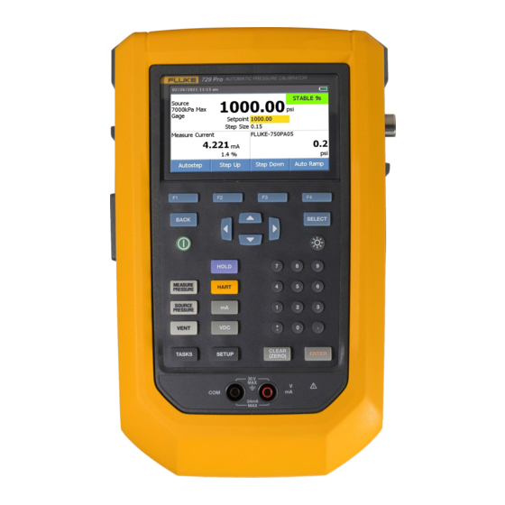
Page 12: Display
External display shows selected device that is connected. The device can be a pressure Setpoint indicator module, temperature probe, process variable (PV) of connected HART device, or Fluke Connect secondary device reading. Main display with measured or Softkey indicator sourced value ... - Page 13 Automatic Pressure Calibrator Display The display can also show different configurations: Typically, the display does shows two functions, see Figure 1. Triple-Function Display for more information. • The upper display for the internal pressure has these functions: ◦ VENT ◦ SOURCE ◦...
- Page 14 729 Pro Users Manual The screen has two sections: The upper display shows the internal pressure controller status and includes: • Mode: Measure, Source, and Vent • Pressure Value: Current measured pressure and unit • Status: Shows nothing in measure mode, NOT READY, STABLE in source mode, and VENTING, VENTED in vent mode.
-
Page 15: Triple-Function Display
Automatic Pressure Calibrator Display Triple-Function Display When the third function (RTD, External Pressure Module, HART Transmitter, or FC secondary device) is connected, the Product changes to triple-function display automatically. In the subsequent triple-function display, the original bottom half of the display is divided into two parts: •... -
Page 16: Pressure Module Connection
729 Pro Users Manual Pressure Module Connection The Product automatically detects external pressure module installation or removal. Move the cursor to the unit type and push E to configure the pressure-unit type (it can be different from the pressure unit of internal pressure). Change the unit type of the internal pressure to automatically change the unit type of the pressure module. -
Page 17: Ports
Automatic Pressure Calibrator Ports Ports Table is a list of the Product ports. Table 4. Product Ports Right Left Right Left Bottom Bottom Item Description USB port – Used for communication between the Product and a PC. Battery charger/universal power supply port. Use the battery charger for bench-top ... -
Page 18: Setup Menu
1234. To access the Setup menu, push S. The Setup menu includes submenus for Product configuration. The submenus are: 1. 729 Pro Information 2. 729 Pro Setup 3. Manage Users 4. Manage Test Results 5. Manage Screen Shots 6. -
Page 19: 729 Pro Information
Automatic Pressure Calibrator Setup Menu 729 Pro Information The 729 Pro Information submenu is an information-only screen that shows information about the Product. The screen shows: • Product model • Serial Number • Firmware Revision: Main, PCM, EMM, and PMM •... -
Page 20: 729 Pro Setup
729 Pro Users Manual 729 Pro Setup The 729 Pro Setup submenu shows the information in Table 5. Table 5. 729 Pro Setup Menu Menu Function Parameter Push E and use the arrows to select the UI language: English, Simplified... -
Page 21: Manage Users
Automatic Pressure Calibrator Setup Menu Manage Users The Manage Users submenu controls access to add or delete Product user names from this menu. To add a new user: 1. Push A (New). Use the onscreen keyboard to add a new user. Push the softkeys for Capslock ON (or OFF), Backspace, and to complete the entry D (Done). -
Page 22: Manage Screen Shots
729 Pro Users Manual Manage Screen Shots The Product can take screen shots of any screen and store them. To take a screen shot: 1. Go to the screen to save. 2. Push and hold H. The Product shows File Saved. -
Page 23: Keypad Test
Automatic Pressure Calibrator Setup Menu 4. To let the water out, turn the knob counterclockwise on the side of the Product. 5. Push D to repeat the drain operation. 6. When finished with water drain, push in on the fitting to release the hose. 7. -
Page 24: Tasks Menu
729 Pro Users Manual Tasks Menu Tasks let you set up calibration and measurement tasks to save and recall for later use. All tasks require that an interchangeable pressure measurement module is installed in the Product. A P/P task requires a pressure module (750P) is connected to the Product. -
Page 25: Pressure Switch (Sw)
Automatic Pressure Calibrator Tasks Menu Figure 5. Pressure Transmitter (P/I) Task Connections Pressure Switch (SW) Use this feature to calibrate a pressure switch. See Figure for connections: 1. From page 1 of the Tasks menu, push the arrows to highlight Pressure Switch (SW). 2. - Page 26 729 Pro Users Manual 5. Push D (Auto Test) or B (Manual Test) to do the As Found switch test. The test runs. After the test runs, the results show on the display. To save the test results: 1. Push D (Done).
-
Page 27: Current To Pressure Test (I/P)
Automatic Pressure Calibrator Tasks Menu Current to Pressure Test (I/P) Use this feature to calibrate a current to pressure (I/P) converter with current source and pressure measurements. See Figures and 8: 1. From page 1 of the Tasks menu, push the arrows to highlight Current to Pressure Test (I/P). -
Page 28: Pressure Leak Test
729 Pro Users Manual Figure 8. Current to Pressure Test (I/P) with Internal Connections To compressed air source To compressed air source I/P Transducer I/P Transducer Pressure Leak Test Use this feature to test a pressure device for leaks. For connections, see Figure 9. -
Page 29: Pressure Transmitter (P/V)
Automatic Pressure Calibrator Tasks Menu Pressure Transmitter (P/V) Use this feature to calibrate a pressure to voltage transmitter with voltage measurement. For connections, see Figure 5. 1. From page 1 of the Tasks menu, push the arrows to highlight Pressure Transmitter (P/V). -
Page 30: Pressure Transmitter (P/P)
729 Pro Users Manual Pressure Transmitter (P/P) To calibrate a pressure-to-pressure transmitter, use this feature. This feature requires a pressure module to measure pressure output from a connected transmitter. To use the function, see Figure 9: 1. From page 1 of the Tasks menu, push the arrows to highlight Pressure Transmitter (P/P). -
Page 31: Hart Functionality
Automatic Pressure Calibrator HART Functionality HART Functionality The Product interfaces with HART devices. It can: • View and modify transmitter setup and data that includes: ◦ Write Lower Range Value (LRV) ◦ Write Upper Range Value (URV) ◦ Write PV Unit ◦... -
Page 32: Loop Power +24V On
729 Pro Users Manual Loop Power +24V ON The Product supplies loop power at 24 V dc to a current transmitter disconnected from the system. To supply 24 V loop power: 1. From the HART menu, push B (Loop Power +24V ON). The Product polls the bus to see if a transmitter is connected. -
Page 33: Hart Menu
Automatic Pressure Calibrator HART Menu HART Menu The HART menu has these functions that configure and calibrate a HART device: • HART Data • HART Service • Calibrate (Ad Hoc) • Find Task by Tag • Bus Polling From the HART menu, push A (Disconnect) to disconnect from HART communication. -
Page 34: Pv Zero Trim
729 Pro Users Manual Highlight the HART Service menu selection and push D (Continue). When you enter some of the submenus, a warning tells you to remove the loop from AUTOMATIC control. Push D (Continue). PV Zero Trim This function sets the digital pressure value of the transmitter to zero. -
Page 35: Device Diagnostics
Automatic Pressure Calibrator HART Menu 4. Enter the Lower Range Value (PV LRV) necessary. 5. Push E to select. 6. Push C (Send) to change the LRV. Device Diagnostics Select Device Diagnostics to send the self-diagnostics command to the connected transmitter and view the transmitter Self Test result. -
Page 36: Adjust
729 Pro Users Manual Test results show after all strategy points have recorded the measurements. Measurements within specification show as black. Measurements out of specification show as red. 1. Push D (Done) or A (Abort). 2. Enter the Tag ID, serial number of the device, and the User ID. -
Page 37: As Left
Automatic Pressure Calibrator Measure Mode As Left Push D (As Left). Repeat the procedure from As Found. Calibration results save to the Test Results menu. Find Task by Tag Downloaded tasks from DPCTrack2 or other supported software are shown: 1. Use the up and down arrows to scroll through the tasks. 2. -
Page 38: Volts Measurement
729 Pro Users Manual Volts Measurement The Product measures 0 V dc to 30 V dc. Figure shows measurement connections for voltage measurements. Figure 11. VDC Measurement Connections – Pressure Measurement The Product supports the 700P and 750P series pressure modules. - Page 39 Automatic Pressure Calibrator Measure Mode To measure pressure: 1. Attach the applicable pressure module for the process pressure you will test as described in the instruction sheet for the module. W Warning To prevent personal injury, shut off the valve and slowly bleed off the pressure before attaching the pressure module to the pressure line to avoid a violent release of pressure in a pressurized system.
-
Page 40: Autostep And Auto Ramp The Output Value
729 Pro Users Manual Figure 13. Pressure Module Connections Isolation Isolation Valve Valve Gage Gage Module Module Differential Differential Module Module Tank Autostep and Auto Ramp the Output Value Autostep and Auto Ramp can automatically adjust the value of source functions for pressure or current. -
Page 41: Auto Ramp The Output
Automatic Pressure Calibrator Auto Ramp the Output 6. Select the Step Style: • B (Sawtooth) • C (Triangle) 7. Push D (Start). The Product automatically starts the step function. The softkey label changes to Stop Step. 8. Push the D (Stop Step) to stop the automatic step function. 9. -
Page 42: Temperature Measurement
See Figure 14. Note The factory default type is PT100-385 so if the Product is used with the Fluke 720 RTD Probe (PN 4366669), it is not necessary to set the probe type. Connect the probe to the Product and configure the display to read temperature. -
Page 43: To 20 Ma Simulation
Automatic Pressure Calibrator Auto Ramp the Output 4. To change the output value, record a new value and push E. 5. To set the output value in the present source function, push P then enter the desired value and push E. 6. -
Page 44: Log
729 Pro Users Manual Users can record a series of pressure or mA measurements for later upload to a host computer. The Product records a maximum of 8000 readings, depending on the reading rate, duration, and how much memory is in use for other functions such as tasks or stored results. -
Page 45: Communication With A Pc
Download procedures from a PC to the Product and upload test results to a PC from the Product. A PC, Microsoft Windows, USB cable (supplied), and Fluke DPCTrack2™ application software, or a qualified Fluke partner’s software are required. See the DPCTrack2 Users Manual for further instructions. See Figure for the connection. -
Page 46: Battery Life
729 Pro Users Manual 4. Remove the battery door. 5. Remove the battery. 6. Connect the battery charger to the input on the battery. The battery charge indicator (top-right of display) shows while the battery is outside of the Product. Solid green bars show the level of charge on the battery. When all bars are illuminated and solid, the battery is fully charged. -
Page 47: Battery Replacement
Accessories. Note Take spent batteries to a qualified recycler or hazardous materials handler for disposal. Contact an authorized Fluke Service Center for recycling information. To replace the battery: 1. Push S and select Maintenance. 2. Push A (Exhaust) to release Product internal pressure. -
Page 48: Pmm Replacement
To update the Product firmware version: 1. Turn on the Product. 2. Connect the USB cable (provided) to a PC. See Figure 16. 3. Use the PC to go to www.fluke.com/productinfo. 4. Click Find your software. 5. Search for 729 Pro. -
Page 49: Calibration Data
Product unless the module is faulty also. Be sure to pack the Product securely, in the original shipping container if it is available. See Contact Fluke and the LIMITED WARRANTY AND LIMITATION OF LIABILITY. - Page 50 729 Pro Users Manual Table 6. Error Messages (cont.) Error Message Explanation Potential Root Cause and Solution Failed to load filesystem Filesystem fatal Data flash memory failure. The main from flash memory at error PCA needs service. start up. Cannot save...
- Page 51 Automatic Pressure Calibrator Maintenance Table 6. Error Messages (cont.) Error Message Explanation Potential Root Cause and Solution 1. Make sure the external pressure module is connected, and run the Lost connection to Running task aborted, task again. external pressure due to lost connection to module, Task external pressure 2.
- Page 52 729 Pro Users Manual Table 6. Error Messages (cont.) Error Message Explanation Potential Root Cause and Solution 1. The pressure volume is too large, reduce the volume and try again. 2. The leakage of pressure volume is too large. Test the leakage and try again.
-
Page 53: Hart Commands
Automatic Pressure Calibrator Maintenance HART Commands See Table for Product HART commands. Table 7. Supported HART Commands Number Command Description Type Read Primary Variable Universal Read Loop Current and Percent of Range Universal Read Dynamic Range and Loop Current Universal Read Dynamic Variable Classification Universal Read Message... -
Page 54: Strap
729 Pro Users Manual Strap Attach the Product carrying strap. See Figure 19. Adjust the straps as necessary to hang the Product on any sturdy support. Figure 19. Product Strap User-Replaceable Parts and Accessories Table is a list of replacement parts and accessories. -
Page 55: Specifications
Automatic Pressure Calibrator Specifications Specifications Pressure Specification 1-year Specification ........0.02 % of full scale Control Specification......... 0.005 % full scale minimum Temperature Compensation ..... 15 °C to 35 °C (59 °F to 95 °F) to rated accuracy Note: For temperatures from -10 °C to +15 °C and 35 °C to 50 °C, 0.04 % of full scale Electrical Specification All specifications are valid to 110 % of range, except 24 mA source and simulate which are valid to 100 %... -
Page 56: Pressure Measurement Module Specification
729 Pro Users Manual Pressure Measurement Module Specification Specification (Total Uncertainty) Pressure Range (psi) Range (kPa) Range (bar) Measurement Module Resolution Resolution Resolution 15 °C to 35 °C <15 °C, >35 °C -15.0000 to 30.0000 -100.000 to 200.000 -1.00000 to 2.00000 Max 0.02 %FS/yr Max 0.04 %FS/yr FLK-PMM-200K 0 to 30.0000... -
Page 57: Electromagnetic Compatibility (Emc)
Automatic Pressure Calibrator Specifications Electromagnetic Compatibility (EMC) International..........IEC 61326-1: Basic Electromagnetic Environment; CISPR 11: Group 1, Class A Group 1: Equipment has intentionally generated and/or uses conductively coupled radio frequency energy that is necessary for the internal function of the equipment itself. Class A: Equipment is suitable for use in all establishments other than domestic and those directly connected to a low-voltage power supply network that supplies buildings used for domestic purposes. - Page 58 729 Pro Users Manual...
Need help?
Do you have a question about the 729 Pro and is the answer not in the manual?
Questions and answers