Tektronix WFM6120 Service Manual
Waveform monitors
Hide thumbs
Also See for WFM6120:
- Technical reference (152 pages) ,
- Security instructions (11 pages) ,
- Release notes (9 pages)

Related Manuals for Tektronix WFM6120


Summary of Contents for Tektronix WFM6120
- Page 1 WFM6120, WFM7020, WFM7120, WFM6100 Opt. MB, WFM7000 Opt. MB, and WFM7100 Opt. MB Waveform Monitors Service Manual *P077008101* 077-0081-01...
-
Page 3: Service Manual
WFM6120, WFM7020, WFM7120, WFM6100 Opt. MB, WFM7000 Opt. MB, and WFM7100 Opt. MB Waveform Monitors Service Manual Revision B Warning The servicing instructions are for use by qualified personnel only. To avoid personal injury, do not perform any servicing unless you are qualified to do so. Refer to all safety summaries prior to performing service. - Page 4 Copyright © Tektronix. All rights reserved. Licensed software products are owned by Tektronix or its subsidiaries or suppliers, and are protected by national copyright laws and international treaty provisions. Tektronix products are covered by U.S. and foreign patents, issued and pending. Information in this publication supersedes that in all previously published material.
- Page 5 Tektronix, with shipping charges prepaid. Tektronix shall pay for the return of the product to Customer if the shipment is to a location within the country in which the Tektronix service center is located. Customer shall be responsible for paying all shipping charges, duties, taxes, and any other charges for products returned to any other locations.
-
Page 7: Table Of Contents
Composite Input Option CPS................Audio Options AD and DDE ................Option EYE/PHY.................... Option 3G/JIT ....................Fan Control ....................2-10 Power Supply and Distribution................2-10 Adjustment Procedures Adjustments ....................... Required Equipment..................Procedures ....................WFM6120, WFM7020, and WFM7120 Waveform Monitors Service Manual... - Page 8 4-27 Module Removal................... 4-28 Repackaging Instructions ..................4-38 Packaging ....................4-38 Shipping to the Service Center ................4-38 Replaceable Parts Replaceable Parts ....................Parts Ordering Information ................. Using the Replaceable Parts Lists................WFM6120, WFM7020, and WFM7120 Waveform Monitors Service Manual...
- Page 9 Figure 5-1: Circuit boards and connectors..............Figure 5-2: Chassis components (B030000 and above)............Figure 5-3: Chassis components (B029999 and below)............Figure 5-4: Main board replaceable components ............5-11 Figure 5-5: Analog audio breakout cable assembly ............5-12 WFM6120, WFM7020, and WFM7120 Waveform Monitors Service Manual...
- Page 10 Table 5-3: Chassis components (B029999 and below) (See Figure 5-3.) ........Table 5-4: Replaceable parts list (See Figure 5-4.) ............5-10 Table 5-5: Replaceable parts list (See Figure 5-5.) ............5-12 Table 5-6: Accessories ..................5-13 WFM6120, WFM7020, and WFM7120 Waveform Monitors Service Manual...
-
Page 11: General Safety Summary
Replace batteries properly. Replace batteries only with the specified type and rating. Use proper fuse. Use only the fuse type and rating specified for this product. Wear eye protection. Wear eye protection if exposure to high-intensity rays or laser radiation exists. WFM6120, WFM7020, and WFM7120 Waveform Monitors Service Manual... - Page 12 WARNING indicates an injury hazard not immediately accessible as you read the marking. CAUTION indicates a hazard to property including the product. The following symbol(s) may appear on the product: WFM6120, WFM7020, and WFM7120 Waveform Monitors Service Manual...
-
Page 13: Service Safety Summary
Use Care When Servicing With Power On. Dangerous voltages or currents may exist in this product. Disconnect power, remove battery (if applicable), and disconnect test leads before removing protective panels, soldering, or replacing components. To avoid electric shock, do not touch exposed connections. WFM6120, WFM7020, and WFM7120 Waveform Monitors Service Manual... - Page 14 Service Safety Summary viii WFM6120, WFM7020, and WFM7120 Waveform Monitors Service Manual...
-
Page 15: Preface
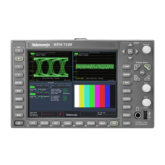
Preface This manual supports servicing to the module level of the WFM6120, WFM7020. and WFM7120 Waveform Monitors, which process video signals for display on an internal XGA LCD. The instrument finds use as a monitor for broadcasting, production, and post-production environments. -
Page 16: Related Manuals
WFM6100 Opt. MB, WFM7000 Opt. list of specifications MB, and WFM7100 Opt. MB Waveform Monitor Specifications and Performance Verification WVR & WFM Series Master Information Programmers command reference for Base controlling the waveform monitor WFM6120, WFM7020, and WFM7120 Waveform Monitors Service Manual... -
Page 17: Introduction
Introduction... -
Page 19: Service Strategy
(See page x, Related Manuals.) Options and Accessories The lists of options and accessories for this product are found in the WFM6120, WFM7020, WFM7120, WFM6100 Opt. MB, WFM7000 Opt. MB, and WFM7100 Opt. MB Waveform Monitor Quick Start User Manual that ships with the product. -
Page 20: Hardware Installation
You can also install the waveform monitor in a custom installation, such as a console. For installation instructions, refer to the WFM6120, WFM7020, WFM7120, WFM6100 Opt. MB, WFM7000 Opt. MB, and WFM7100 Opt. MB Waveform Monitor Quick Start User Manual. -
Page 21: Theory Of Operation
Theory of Operation... - Page 23 Composite inputs. Audio options can add inputs for digital only or analog audio capability. The WFM6120 is similar, except that it does not support HD rate video signals. All models use an internal XGA monitor for the display, and have an output to drive an external XGA monitor with the same display.
-
Page 24: Figure 2-1: Main Block Diagram
Theory of Operation Figure 2-1: Main block diagram 2–2 WFM6120, WFM7020, and WFM7120 Waveform Monitors Service Manual... -
Page 25: Main Board
XGA DAC to drive the external monitor. Note that the parallel data from the serial digital inputs connect directly to this FPGA to provide the picture functionality, bypassing the waveform processing engine. WFM6120, WFM7020, and WFM7120 Waveform Monitors Service Manual 2–3... -
Page 26: Front Panel
Option DDE adds support for Dolby E decode, Dolby Digital (AC-3) decode, Digital audio monitoring (embedded and AES/EBU), and for Analog audio monitoring. This option is available for WFM7120 and WFM6120 only. 2–4 WFM6120, WFM7020, and WFM7120 Waveform Monitors Service Manual... -
Page 27: Option Eye/Phy
Eye parameter measurements. Options EYE and PHY provide the following features: Eye pattern display Equalized Eye pattern display Jitter readout Jitter Meter Cable Loss readout WFM6120, WFM7020, and WFM7120 Waveform Monitors Service Manual 2–5... - Page 28 These measurements are read by the CPU on the Main board, which calculates Cable Loss, Approximate Cable Length, and Source Level for display in the SDI Status screen. 2–6 WFM6120, WFM7020, and WFM7120 Waveform Monitors Service Manual...
-
Page 29: Figure 2-2: Option Eye/Phy Block Diagram
Theory of Operation Figure 2-2: Option EYE/PHY block diagram WFM6120, WFM7020, and WFM7120 Waveform Monitors Service Manual 2–7... -
Page 30: Option 3G/Jit
CLOCK OUT signal. An external oscilloscope viewing a copy of the 3 Gbps input signal can be triggered from the CLOCK OUT signal in order to display an eye diagram. 2–8 WFM6120, WFM7020, and WFM7120 Waveform Monitors Service Manual... -
Page 31: Figure 2-3: Option 3G/Jit Block Diagram
Theory of Operation Figure 2-3: Option 3G/JIT block diagram WFM6120, WFM7020, and WFM7120 Waveform Monitors Service Manual 2–9... -
Page 32: Fan Control
Fuses on the Primary supply 5 V output protect the main board. The secondary supplies and their tolerances are specified in the troubleshooting section. The location of the supply test points is shown in the Maintenance section. 2–10 WFM6120, WFM7020, and WFM7120 Waveform Monitors Service Manual... -
Page 33: Adjustment Procedures
Adjustment Procedures... -
Page 35: Adjustments
Performance Verification procedure: HD Cable Meter (WFM7120 Option EYE or PHY only), SD Cable Meter (WFM6120 Option EYE and WFM7120 Options SD and EYE or PHY only), HD Jitter Noise Floor (WVR7120 Option EYE or PHY only),... - Page 36 800 mV. e. Press and hold STATUS, and then select SAVE and press SEL. Repeat for the SDI B input. 3–2 WFM6120, WFM7020, and WFM7120 Waveform Monitors Service Manual...
- Page 37 5. Press the left arrow key to return to the first level of the CONFIG menu. 6. Connect an XGA to 5x BNC adapter cable to the PixMon output on the waveform monitor. WFM6120, WFM7020, and WFM7120 Waveform Monitors Service Manual 3–3...
- Page 38 5. Select Composite Waveform Gain, and then press SEL. 6. Follow the on-screen instructions to adjust the gain. 7. Follow the instructions at the bottom of the screen to Save and Exit Calibration mode. 3–4 WFM6120, WFM7020, and WFM7120 Waveform Monitors Service Manual...
- Page 39 8. If multiple inputs require adjustment, repeat steps 2 through 7 for each input. This ends the adjustment procedure. To complete the process you should now perform a complete Performance Verification. WFM6120, WFM7020, and WFM7120 Waveform Monitors Service Manual 3–5...
- Page 40 Adjustments 3–6 WFM6120, WFM7020, and WFM7120 Waveform Monitors Service Manual...
-
Page 41: Maintenance
Maintenance... -
Page 43: General Maintenance
4. Nothing capable of generating or holding a static charge should be allowed on the work station surface. 5. Handle circuit boards by the edges when possible. WFM6120, WFM7020, and WFM7120 Waveform Monitors Service Manual 4–1... -
Page 44: Inspection And Cleaning
Use a glass cleaner to clean the LCD. For the rest of the instrument, use a 75% isopropyl alcohol solution as a cleaner and rinse with deionized water. Before using any other type of cleaner, consult your Tektronix Service Center or representative. -
Page 45: Table 4-1: External Inspection Checklist
Loose, broken, or corroded Remove and replace solder connections. damaged circuit board. Burned circuit boards. Burned, broken, or cracked circuit-run plating. Resistors Burned, cracked, broken, Remove and replace blistered condition. damaged circuit board. WFM6120, WFM7020, and WFM7120 Waveform Monitors Service Manual 4–3... - Page 46 5. Spray wash dirty parts with the isopropyl alcohol and wait 60 seconds for the majority of the alcohol to evaporate. 6. Dry all parts with low-pressure, deionized air. Lubrication. There is no periodic lubrication required for the waveform monitor. 4–4 WFM6120, WFM7020, and WFM7120 Waveform Monitors Service Manual...
-
Page 47: Troubleshooting
Standard boards and modules: Power Supply Display Assembly (LCD, Backlight inverter, Front Panel board with buttons, LEDs, and knobs Main board Mezzanine SDI I/O board (not present if Option EYE/PHY or 3G is installed) WFM6120, WFM7020, and WFM7120 Waveform Monitors Service Manual 4–5... -
Page 48: Table 4-3: Required Test Equipment
AM700 and AM70. Voltmeter Fluke 87 or equivalent DC Ammeter with Clamp on pickup 20 Amp DC capable Fluke 336 or equivalent Oscilloscope Video trigger capability Tektronix TDS3000C Series 4–6 WFM6120, WFM7020, and WFM7120 Waveform Monitors Service Manual... -
Page 49: Table 4-4: Symptoms And Causes
Perform primary power supply checks Perform secondary power supply checks Composite DAC Comm: Run Advanced Diagnostics and look for other information Composite SPI Comm: Replace the Composite board Front Panel Version Information WFM6120, WFM7020, and WFM7120 Waveform Monitors Service Manual 4–7... - Page 50 If only this test fails, then perform the Isolating Advanced Diagnostic Lissajous Errors procedure ADV_DIAG_LSS to isolate the problem to main or audio board. 4–8 WFM6120, WFM7020, and WFM7120 Waveform Monitors Service Manual...
- Page 51 DSP2 QDR2 RD SDRAM Data RD SDRAM Address DSP1 SDRAM Data Bus DSP1 SDRAM Address Bus DSP2 SDRAM Data Bus DSP2 SDRAM Address Bus Audio PLL Ctrl Outs Audio PLL Freq Check WFM6120, WFM7020, and WFM7120 Waveform Monitors Service Manual 4–9...
- Page 52 If only this test fails, then perform the Isolating Advanced Diagnostic Lissajous Errors procedure Lissajous Bus to isolate the problem to main or audio board. 4–10 WFM6120, WFM7020, and WFM7120 Waveform Monitors Service Manual...
- Page 53 Search for an intermittent problem in the audio board, cables, or main board. Fail AUDIO_DSP_HEARTBEAT No text or traces on LCD Perform LCD troubleshooting test Traces on LCD but not on Ext Replace Main board Display output WFM6120, WFM7020, and WFM7120 Waveform Monitors Service Manual 4–11...
- Page 54 If the performance changes with the audio board removed, then you should perform the primary and secondary power supply checks and look for an excess load on one of the supplies. 4–12 WFM6120, WFM7020, and WFM7120 Waveform Monitors Service Manual...
-
Page 55: Detailed Troubleshooting Procedures
3.3 V square wave on the tachometer feedback line. Replace the fan if the pull up is intact but there is no signal on the tachometer line WFM6120, WFM7020, and WFM7120 Waveform Monitors Service Manual 4–13... - Page 56 Be sure all seven 5 V fuses are good (as noted in Primary Power Supply Tests) Tests before checking the secondary supplies. First, check the LEDs near the power connector, J14. Green LED DS232 indicates there is some 5 V from the main supply. 4–14 WFM6120, WFM7020, and WFM7120 Waveform Monitors Service Manual...
-
Page 57: Table 4-5: Main Board Secondary Supplies
62 pin DSUB connector is mounted. The test points are available, with the board installed, along the top front edge of the board. (See Figure 4-3 on page 4-26.). WFM6120, WFM7020, and WFM7120 Waveform Monitors Service Manual 4–15... -
Page 58: Table 4-7: Analog Audio Secondary Supplies (Board Not Present For Option Ds Instrument)
It may help to be in a low light area to see the backlight. 5. If the backlight is on, replace the front panel assembly. 4–16 WFM6120, WFM7020, and WFM7120 Waveform Monitors Service Manual... - Page 59 1. Prepare a test oscilloscope with the following settings: Control Setting Vertical Scale 2.00 V/div Horizontal Scale 5.00 µs/div WFM6120, WFM7020, and WFM7120 Waveform Monitors Service Manual 4–17...
- Page 60 Probe pin B21 on audio board connector J641 during the boot sequence. If the signal does not toggle, replace the audio board; otherwise, replace the main board. If all of these steps pass, replace the audio board. 4–18 WFM6120, WFM7020, and WFM7120 Waveform Monitors Service Manual...
- Page 61 Pass/Fail tests, a lower section which shows SDI and Video bus activity, and, finally, narrow YRGB ramps at the very top and bottom to look for missing bits on the display interconnect. WFM6120, WFM7020, and WFM7120 Waveform Monitors Service Manual 4–19...
-
Page 62: Table 4-8: Advanced Diagnostic Measurements
A failure in this data path can be due to a problem on either board. Diagnostic Lissajous Errors Perform the following tests to isolate the problem to one board or the other. 4–20 WFM6120, WFM7020, and WFM7120 Waveform Monitors Service Manual... - Page 63 Eye display bandwidth, rise and fall time, and transient response aberrations are controlled by circuits contained on the Eye board. WFM6120, WFM7020, and WFM7120 Waveform Monitors Service Manual 4–21...
- Page 64 3G board. Jitter Waveform Display Problems. Jitter Waveform display for 3 Gbps signals is available only with option JIT. The jitter waveform is derived from the sampled recovered clock sine wave. 4–22 WFM6120, WFM7020, and WFM7120 Waveform Monitors Service Manual...
- Page 65 HD, SD, or analog composite signal is detected at the selected input. The Loop Out Test Signal generation is contained wholly on the 3 Gbps board. WFM6120, WFM7020, and WFM7120 Waveform Monitors Service Manual 4–23...
-
Page 66: Figure 4-1: Main Board Power Supply Test Points And Leds
General Maintenance Figure 4-1: Main board power supply test points and LEDs 4–24 WFM6120, WFM7020, and WFM7120 Waveform Monitors Service Manual... -
Page 67: Figure 4-2: Audio Main Board Power Supply Test Point Locations
General Maintenance Figure 4-2: Audio Main board power supply test point locations WFM6120, WFM7020, and WFM7120 Waveform Monitors Service Manual 4–25... -
Page 68: Figure 4-3: Analog Audio Board Power Supply Test Point Locations
General Maintenance Figure 4-3: Analog audio board power supply test point locations 4–26 WFM6120, WFM7020, and WFM7120 Waveform Monitors Service Manual... -
Page 69: Removal And Replacement Procedures
Table 4-9: Tools required for module removal Item General Tool Name Description number Accepts Torx-driver bits 620-440 Screwdriver handle T-10 Torx tip Used for removing most instrument 640-235 screws. Torx-driver bit for T-10 size screw heads WFM6120, WFM7020, and WFM7120 Waveform Monitors Service Manual 4–27... -
Page 70: Module Removal
Audio Power Front You must first remove Composite Mezzanine or 3G assy supply Main panel assy Top cover Board supports Composite Mezzanine EYE/PHY or 3G Analog audio Audio main Main board 4–28 WFM6120, WFM7020, and WFM7120 Waveform Monitors Service Manual... - Page 71 Rear Panel The rear panel is formed by the chassis and the individual module rear panels, which overlap and are bolted together. (See Figure 4-4 on page 4-30.) WFM6120, WFM7020, and WFM7120 Waveform Monitors Service Manual 4–29...
-
Page 72: Figure 4-4: Module Securing Screws
3. Remove the two T-15 screws securing the Mezzanine board to the Main board. 4. Move the Mezzanine board toward the front of the instrument until the BNC connectors clear the rear panel, then lift it up out of the instrument. 4–30 WFM6120, WFM7020, and WFM7120 Waveform Monitors Service Manual... - Page 73 (See Table 4-9 on page 4-27.) 5. Remove the Audio module rear panel from the two circuit boards. 6. Separate the Audio module circuit boards at J1130. WFM6120, WFM7020, and WFM7120 Waveform Monitors Service Manual 4–31...
- Page 74 USB connectors, until they clear the LCD bracket. 3. Disconnect the cables connecting the Front panel/LCD assembly to the Main board at J17, J18, and J29. (See Figure 4-5 on page 4-33.) 4–32 WFM6120, WFM7020, and WFM7120 Waveform Monitors Service Manual...
-
Page 75: Figure 4-5: Front Panel Cable Connections
6. Use a spudger or other tool to pry the bezel clips away from the bracket and then pull the bezel away, leading the front panel cable through the cutout in the bracket. WFM6120, WFM7020, and WFM7120 Waveform Monitors Service Manual 4–33... -
Page 76: Figure 4-6: Front Panel Disassembly
3. Remove the two screws attached to the right-hand bracket of the LCD display assembly. The right-hand bracket is on the right when the assembly is facing you as shown. (See Figure 4-7.) 4–34 WFM6120, WFM7020, and WFM7120 Waveform Monitors Service Manual... -
Page 77: Figure 4-7: Lcd Assembly Bracket And Backlight Lock
CAUTION. To prevent damage, do not bend the flex circuitry. Carefully remove the flex circuit from the metal guides and connector latch. WFM6120, WFM7020, and WFM7120 Waveform Monitors Service Manual 4–35... -
Page 78: Figure 4-8: Backlight Removal (B030000 And Above)
7. Carefully remove the flex circuit from the metal guides. 8. Pull the backlight straight out (to the right) from the assembly. 9. To remove the other backlight, repeat the previous four steps. 4–36 WFM6120, WFM7020, and WFM7120 Waveform Monitors Service Manual... - Page 79 5. When reassembling, make sure to route the backlight cables as noted in step 3, behind the Front Panel standoffs and clear of the cutout for the USB/Headphone connectors. WFM6120, WFM7020, and WFM7120 Waveform Monitors Service Manual 4–37...
-
Page 80: Repackaging Instructions
Type and serial number of the instrument. Reason for returning. A complete description of the service required. Mark the address of the Tektronix Service Center and the return address on the shipping carton in two prominent locations. 4–38 WFM6120, WFM7020, and WFM7120 Waveform Monitors Service Manual... -
Page 81: Replaceable Parts
Replaceable Parts... -
Page 83: Parts Ordering Information
For more information about the module exchange program, call 1-800-833-9200. Outside North America, contact a Tektronix sales office or distributor; see the Tektronix Web site for a list of offices: www.tektronix.com. Module Repair and Return. You may ship your module to us for repair, after which we will return it to you. -
Page 84: Using The Replaceable Parts Lists
Using the Replaceable Parts Lists This section contains lists of the mechanical and/or electrical components that are replaceable for the WFM6120, WFM7020, and WFM7120 Waveform Monitor. Use this list to identify and order replacement parts. The following table describes each column in the parts list. - Page 85 CONN,DSUB; PCB;FEMALE,RTANG,DUAL STACKED,15 POS HD LOWER,9 POS UPPER,SAFETY CONTROLLED 211-0722-00 SCREW,MACHINE; 6-32 X 0.250,PNH,STL,CDPL,T-15 TORX DR 131-7257-00 CONN,JACK; PCB/PNL,RJ45,CAT5,W/LEDS YELLOW & GREEN,FEMALE,RTANG,8 POS,0.1 CTR,0.528 H X 0.138 TAIL,10/100 BASE TX AND RX MAGNETICS MODULE,SAFETY CONTROLLED WFM6120, WFM7020, and WFM7120 Waveform Monitors Service Manual 5–3...
- Page 86 H X 0.125 TAIL, 30 GOLD, 4-40 THD INSERTS, BOARD RETENTION, HIGH DENSITY CONN 211-0722-00 SCREW,MACHINE; 6-32 X 0.250,PNH,STL,CDPL,T-15 TORX DR (USED WITH WFM7F02 PORTABLE CASE ONLY) Quantity will vary depending on instrument model and installed options. 5–4 WFM6120, WFM7020, and WFM7120 Waveform Monitors Service Manual...
-
Page 87: Figure 5-1: Circuit Boards And Connectors
Replaceable Parts Figure 5-1: Circuit boards and connectors WFM6120, WFM7020, and WFM7120 Waveform Monitors Service Manual 5–5... -
Page 88: Table 5-2: Chassis Components (B030000 And Above) (See Figure 5-2.)
MARKER, IDENT, FRONT PANEL ID W/O COMPOSITE, W/EYE, WFM7120 335-1842-00 MARKER,IDENT, FRONT PANEL ID W/O COMPOSITE, W/EYE, WFM7020 335-1843-00 MARKER,IDENT, FRONT PANEL ID W/O COMPOSITE, W/EYE, WFM6120 174-5001-00 CABLE ASSEMBLY, 10 PIN; 6.0 INCHES; 28AWG, U STYLE 1061 211-0382-00 SCREW,MACHINE; 4-40X0.500,PAN HEAD,T-10 TORX,CD PL 119-7439-00 DISPLAY MODULE;... -
Page 89: Figure 5-2: Chassis Components (B030000 And Above)
Replaceable Parts Figure 5-2: Chassis components (B030000 and above) WFM6120, WFM7020, and WFM7120 Waveform Monitors Service Manual 5–7... -
Page 90: Table 5-3: Chassis Components (B029999 And Below) (See Figure 5-3.)
3.22MM COIN CELL WITH SOLDER TABS,CR2032-1HF1 131-6521-00 CONTACT,ELEC; EMI,CLIP-ON,0.38 L X 0.500 W (2 CONTACTS) X 0.45 H,ELECTROLESS NICKEL PLATE 407-4999-00 BRACKET; FAN MOUNTING,0.050 AL,SAFETY CONTROLLED 650-5134-00 LCD & DISPLAY SHIELD, ASSY 214-5152-00 SPRING,CLIP; EMI 5–8 WFM6120, WFM7020, and WFM7120 Waveform Monitors Service Manual... -
Page 91: Figure 5-3: Chassis Components (B029999 And Below)
Replaceable Parts Figure 5-3: Chassis components (B029999 and below) WFM6120, WFM7020, and WFM7120 Waveform Monitors Service Manual 5–9... -
Page 92: Table 5-4: Replaceable Parts List (See Figure 5-4.)
FUSE; 3.0A,125V,FAST BLOW,0.1 X 0.1 X 0.24,UL REG,CSA CERT,SAFETY CONTROLLED 159-5003-00 FUSE,THRM,CHIP; SELF RESETTING FUSE,1.1A HOLD,2.2A TRIP AT 20 DEG C,30V MAX,SAFETY CONTROLLED 159-5014-00 FUSE; 2.0A,125V,FAST BLOW,0.1 X 0.1 X 0.24,UL REG,CSA CERT,SAFETY CONTROLLED 5–10 WFM6120, WFM7020, and WFM7120 Waveform Monitors Service Manual... -
Page 93: Figure 5-4: Main Board Replaceable Components
Replaceable Parts Figure 5-4: Main board replaceable components WFM6120, WFM7020, and WFM7120 Waveform Monitors Service Manual 5–11... -
Page 94: Figure 5-5: Analog Audio Breakout Cable Assembly
012-1658-00 CABLE ASSEMBLY; ANALOG/AUDIO BREAKOUT 200-4804-00 COVER; SHIELD,ELEC CONN,37 POS DSUB,ZINC 131-0422-00 CONN,DSUB; SLDR CUP/PNL,;MALE,STR,37 POS,0.112 CTR,0.186 H X 0.126 TAIL,0.125 DIA THRU MTG Figure 5-5: Analog audio breakout cable assembly 5–12 WFM6120, WFM7020, and WFM7120 Waveform Monitors Service Manual... -
Page 95: Table 5-6: Accessories
CABINET; PORTABLE CABINET WITH HANDLE,FEET,TILT BAIL AND FRONT PANEL COVER 200-4716-00 COVER,FRONT; PROTECTIVE,PC/ABS FR110,TV GRAY WFM7F05 RACK ADAPTER; DUAL SIDE BY SIDE FOR WFM700,1700 SERIES AND WFM601 SERIES 071-2227-xx MANUAL,TECH;SERVICE MANUAL, WFM6120/WFM7020/WFM7120 012-1658-00 CABLE ASSEMBLY; ANALOG/AUDIO BREAKOUT WFM6120, WFM7020, and WFM7120 Waveform Monitors Service Manual 5–13...
Need help?
Do you have a question about the WFM6120 and is the answer not in the manual?
Questions and answers