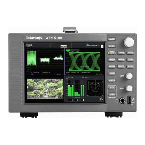
Tektronix WFM6100 Service Manual
Waveform monitor, with option fp
Hide thumbs
Also See for WFM6100:
- Technical reference (174 pages) ,
- Quick start user manual (149 pages) ,
- Instructions manual (19 pages)
Table of Contents
Advertisement
Quick Links
Download this manual
See also:
Instruction Manual
Service Manual
WFM6100, WFM7000, and WFM7100
Waveform Monitor
With Option FP
077-0090-00
Warning
The servicing instructions are for use by qualified
personnel only. To avoid personal injury, do not
perform any servicing unless you are qualified to
do so. Refer to all safety summaries prior to
performing service.
www.tektronix.com
Advertisement
Table of Contents
Troubleshooting

Related Manuals for Tektronix WFM6100


Summary of Contents for Tektronix WFM6100
-
Page 1: Service Manual
Service Manual WFM6100, WFM7000, and WFM7100 Waveform Monitor With Option FP 077-0090-00 Warning The servicing instructions are for use by qualified personnel only. To avoid personal injury, do not perform any servicing unless you are qualified to do so. Refer to all safety summaries prior to performing service. - Page 2 Copyright © Tektronix. All rights reserved. Licensed software products are owned by Tektronix or its subsidiaries or suppliers, and are protected by national copyright laws and international treaty provisions. Tektronix products are covered by U.S. and foreign patents, issued and pending. Information in this publication supercedes that in all previously published material.
- Page 3 Warranty 2 Tektronix warrants that this product will be free from defects in materials and workmanship for a period of one (1) year from the date of shipment. If any such product proves defective during this warranty period, Tektronix, at its option, either will repair the defective product without charge for parts and labor, or will provide a replacement in exchange for the defective product.
-
Page 5: Table Of Contents
............3- - 1 WFM6100, WFM7000, and WFM7100 With Option FP Service Manual... - Page 6 ........... 5- - 2 WFM6100, WFM7000, and WFM7100 With Option FP Service Manual...
- Page 7 ....... . 4- -27 WFM6100, WFM7000, and WFM7100 With Option FP Service Manual...
- Page 8 ....5- -9 Figure 5- -4: Analog audio breakout cable assembly ....5- -10 WFM6100, WFM7000, and WFM7100 With Option FP Service Manual...
-
Page 9: General Safety Summary
Do Not Operate With Suspected Failures. If you suspect there is damage to this product, have it inspected by qualified service personnel. Do Not Operate in Wet/Damp Conditions. WFM6100, WFM7000, and WFM7100 With Option FP Service Manual... - Page 10 CAUTION indicates a hazard to property including the product. Symbols on the Product. The following symbols may appear on the product: Protective Ground CAUTION WARNING Standby Refer to Manual High Voltage (Earth) Terminal WFM6100, WFM7000, and WFM7100 With Option FP Service Manual...
-
Page 11: Service Safety Summary
Disconnect power, remove battery (if applicable), and disconnect test leads before removing protective panels, soldering, or replacing components. To avoid electric shock, do not touch exposed connections. WFM6100, WFM7000, and WFM7100 With Option FP Service Manual... - Page 12 Service Safety Summary viii WFM6100, WFM7000, and WFM7100 With Option FP Service Manual...
-
Page 13: Preface
Preface This manual supports servicing to the module level of the WFM6100, WFM7000, and WFM7100 Waveform Monitors With Option FP, which process video signals for display on an internal XGA LCD. The instrument is a monitor for broadcasting, production, and post-production environments. - Page 14 WVR7100, WFM7000, and WFM7100 Waveform Monitor Procedure for checking performance and list of With Option FP Specifications and Performance specifications Verification WVR & WFM Series Master Information Base Programmer command reference for controlling the instrument WFM6100, WFM7000, and WFM7100 With Option FP Service Manual...
-
Page 15: Introduction
WFM6100, WFM7000, and WFM7100 Waveform Monitors With Option FP Specifications and Performance Verification manual. Options and Accessories The lists of options and accessories for this product are found in the WFM6100, WFM7000, and WFM7100 Waveform Monitors With Option FP Quick Start User Manual. -
Page 16: Product Upgrade
You can also install the waveform monitor in a custom installation, such as a console. For installation instructions, refer to the WFM6100, WFM7000, and WFM7100 Waveform Monitors With Option FP Quick Start User Manual. -
Page 17: Theory Of Operation
Composite inputs. Audio options can add inputs for digital only or analog audio capability. The WFM6100 is similar, except that it does not support HD rate video signals. All models use an internal XGA monitor for the display, and have an output to drive an external XGA monitor with the same display. -
Page 18: Figure 2- 1: Main Block Diagram
Ground Closure I/O Interposer PLD and Memory Front Panel Core and Buttons & Knobs Peripherals Power Ethernet 10.100 Supply Touch Screen Ethernet MAC/PHY Main Board Figure 2- 1: Main block diagram 2- 2 WFM6100, WFM7000, and WFM7100 With Option FP Service Manual... -
Page 19: Main Board
XGA DAC to drive the external monitor. Note that the parallel data from the serial digital input connects directly to this FPGA to provide the picture functionality, bypassing the waveform processing engine. 2- 3 WFM6100, WFM7000, and WFM7100 With Option FP Service Manual... -
Page 20: Control Processor
A-to-D converter to generate a 14-bit parallel signal, which is routed to the DSP FPGA on the Main board, where it is processed (regenerates sub-carrier and demodulates) in the digital domain. 2- 4 WFM6100, WFM7000, and WFM7100 With Option FP Service Manual... -
Page 21: Audio Options: Options Ds, Ad, Dd, And Dde
H Option DD adds support for Dolby Digital (AC- -3) decode, Digital audio monitoring (embedded and AES/EBU), and for Analog audio monitoring. This option is available for WFM7100 and WFM6100 only. H Option DDE adds support for Dolby E decode, Dolby Digital (AC- -3) decode, Digital audio monitoring (embedded and AES/EBU), and for Analog audio monitoring. -
Page 22: Option Eye/Phy
Options EYE and PHY support both HD and SD SDI signals, limited by the capability of the instrument they are installed in: H WFM6100: SD only. H WFM7100: HD only, SD only, or both, depending on installed options. 2- 6 WFM6100, WFM7000, and WFM7100 With Option FP Service Manual... -
Page 23: Fan Control
Fuses on the Primary supply 5 V output protect the main board. The secondary supplies and their tolerances are specified in the troubleshooting section. The location of the supply test points is shown in Maintenance section. 2- 7 WFM6100, WFM7000, and WFM7100 With Option FP Service Manual... -
Page 24: Figure 2- 2: Option Eye/Phy Block Diagram
Interposer PLD and Memory Front Panel Core and Buttons & Knobs Peripherals Power Ethernet 10.100 Supply Touch Screen Ethernet MAC/PHY Main Board Figure 2- 2: Option EYE/PHY block diagram 2- 8 WFM6100, WFM7000, and WFM7100 With Option FP Service Manual... -
Page 25: Adjustments
After making the the adjustment shown here, repeat the failed Performance Verification step. Required Equipment These adjustment procedures require the same equipment as the Performance Verification procedure. See Specifications and Performance Verification for full details. 3- 1 WFM6100, WFM7000, and WFM7100 With Option FP Service Manual... -
Page 26: Procedures
Follow the instructions at the bottom of the screen to Save and Exit Calibration mode. Restart the HD Jitter Noise Floor test, and then record the new values in the test record. 3- 2 WFM6100, WFM7000, and WFM7100 With Option FP Service Manual... - Page 27 8. Press the left arrow key twice to return to the first level of the CONFIG menu. 9. Select Utilities > Calibration. Press SEL to start calibration. 10. Navigate to the Pixmon YPbPr Gain calibration case, and press SEL to start. 3- 3 WFM6100, WFM7000, and WFM7100 With Option FP Service Manual...
- Page 28 1. Perform the following steps if the Offset is outside the specification: DC Offset Restore Off 2. Press the Config button. (Option CPS) 3. Select Utilities > Calibration, and then press SEL to enter the calibration menu. 3- 4 WFM6100, WFM7000, and WFM7100 With Option FP Service Manual...
- Page 29 7. Follow the instructions at the bottom of the screen to Save and Exit calibration mode. 8. Repeat the Composite Analog Frequency Response test in the Performance Verification procedure. 3- 5 WFM6100, WFM7000, and WFM7100 With Option FP Service Manual...
- Page 30 8. If multiple inputs require adjustment, repeat steps 2 through 7 for each input. This ends the adjustment procedure. To complete the process you should now perform a complete Performance Verification. 3- 6 WFM6100, WFM7000, and WFM7100 With Option FP Service Manual...
-
Page 31: General Maintenance
4. Nothing capable of generating or holding a static charge should be allowed on the work station surface. 5. Handle circuit boards by the edges when possible. 4- 1 WFM6100, WFM7000, and WFM7100 With Option FP Service Manual... -
Page 32: Inspection And Cleaning
Use a swab to clean narrow spaces around controls and connectors. Do not use abrasive compounds on any part of the instrument that may damaged by it. 4- 2 WFM6100, WFM7000, and WFM7100 With Option FP Service Manual... -
Page 33: Table 4- -1: External Inspection Checklist
Use a glass cleaner to clean the LCD. For the rest of the instrument, use a 75% isopropyl alcohol solution as a cleaner and rinse with deionized water. Before using any other type of cleaner, consult your Tektronix Service Center or representative. -
Page 34: Table 4- -2: Internal Inspection Checklist
75% isopropyl alcohol by doing steps 4 through 6. 4. Gain access to the parts to be cleaned by removing easily accessible shields and panels. 4- 4 WFM6100, WFM7000, and WFM7100 With Option FP Service Manual... -
Page 35: Troubleshooting
Standard boards and modules: H Power Supply H Display Assembly (LCD, Backlight inverter, Front Panel board with buttons, LEDs, and knobs) 4- 5 WFM6100, WFM7000, and WFM7100 With Option FP Service Manual... -
Page 36: Table 4- 3: Required Test Equipment
(Option AD, DD, or DDE) and AM70. Voltmeter Fluke 87 or equivalent DC Ammeter with Clamp on pickup 20 Amp DC capable Fluke 336 or equivalent Oscilloscope Video trigger capability Tektronix TDS3000B Series 4- 6 WFM6100, WFM7000, and WFM7100 With Option FP Service Manual... -
Page 37: Table 4- 4: Symptoms And Causes
Perform primary power supply checks. Composite DAC Comm: Perform secondary power supply checks. Composite SPI Comm: Run Advanced Diagnostics and look for other information. Front Panel Version Information Replace the Composite board. 4- 7 WFM6100, WFM7000, and WFM7100 With Option FP Service Manual... - Page 38 Main board and perform the primary and secondary power supply tests. ADV_DIAG_LSS If only this test fails, then perform Isolating Advanced Diagnostic Lissajous Errors procedure to isolate the problem to Main or Audio board. 4- 8 WFM6100, WFM7000, and WFM7100 With Option FP Service Manual...
- Page 39 H DSP2 → DSY Bus Input H DSP1 → DSP2 Bus Output H DSP1 → DSP2 Bus Input H DSP2 → DSP1 Bus Output H DSP2 → DSP1 Bus Input 4- 9 WFM6100, WFM7000, and WFM7100 With Option FP Service Manual...
- Page 40 Search for an intermittent problem in the Audio board, cables, or Main board. H Fail AUDIO_DSP_HEARTBEAT No text or traces on LCD Perform LCD troubleshooting test. Traces on LCD but not on Display XGA Replace Main board. output 4- 10 WFM6100, WFM7000, and WFM7100 With Option FP Service Manual...
- Page 41 If the performance changes with the Audio board removed, then you should perform the primary and secondary power supply checks and look for an excess load on one of the supplies. 4- 11 WFM6100, WFM7000, and WFM7100 With Option FP Service Manual...
-
Page 42: Detailed Troubleshooting Procedures
If the fan is spinning, but LED DS861 is lit, the problem is probably the tachometer feedback line on pin 3 of the fan. Inspect the wiring and pull- -up 4- 12 WFM6100, WFM7000, and WFM7100 With Option FP Service Manual... -
Page 43: Primary Power Supply Tests
There are multiple secondary supplies that are derived from the main 5 V supply. Be sure all seven 5 V fuses are good (as noted in Primary Power Supply Tests) Tests before checking the secondary supplies. 4- 13 WFM6100, WFM7000, and WFM7100 With Option FP Service Manual... -
Page 44: Table 4- 5: Main Board Secondary Supplies
3.1 to 3.6 - - 5 V - - 4.5 to –5.5 +5 V 4.75 to 5.2 TP10 +1.26 V 1.20 to 1.32 TP11 +1.8 V 1.71 to 1.89 TP95 4- 14 WFM6100, WFM7000, and WFM7100 With Option FP Service Manual... -
Page 45: Front Panel Button Troubleshooting
1. Connect an external XGA monitor to the “Display” output on the rear of the instrument. 2. Cycle the power and watch the external monitor. If the monitor does not display the boot up messages and normal operational screen replace the Main board. 4- 15 WFM6100, WFM7000, and WFM7100 With Option FP Service Manual... -
Page 46: Audio Post Failure
If any errors are found, perform the following procedure to narrow the problem to either the Audio board, the Main board, or the connection between them. 4- 16 WFM6100, WFM7000, and WFM7100 With Option FP Service Manual... - Page 47 Probe pin B21 on the audio board connector J641 during the boot sequence. If the signal does not toggle, replace the Audio board; otherwise, replace the Main board. If all of these steps pass, replace the Audio board. 4- 17 WFM6100, WFM7000, and WFM7100 With Option FP Service Manual...
-
Page 48: Examine Power On Self Tests (Post) Results In The Diagnostic Log
Pass/Fail tests, a lower section which shows SDI and Video bus activity, and, finally, narrow YRGB ramps at the very top and bottom to look for missing bits on the display interconnect. 4- 18 WFM6100, WFM7000, and WFM7100 With Option FP Service Manual... -
Page 49: Isolating Advanced Diagnostic Lissajous Errors
The advanced diagnostics tests the lissajous data path between the Audio and Diagnostic Lissajous Main boards. A failure in this data path can be due to problem on either board. Errors 4- 19 WFM6100, WFM7000, and WFM7100 With Option FP Service Manual... -
Page 50: Option Eye/Phy Troubleshooting
H Check that the ribbon cable from the Eye board to the main board is securely plugged into J5 on the eye board and J16 on the Main board. 4- 20 WFM6100, WFM7000, and WFM7100 With Option FP Service Manual... -
Page 51: Adjustments 3
Operation is unlikely to fail if the basic Eye pattern display works correctly. It is normal for these measurements to stop or become intermittent if there is excessive waveform noise, aberrations, jitter, or cable loss. 4- 21 WFM6100, WFM7000, and WFM7100 With Option FP Service Manual... -
Page 52: Figure 4- 1: Main Board Power Supply Test Points And Leds
DS231 DS232 F221, F222, F223 F231, F232, F233, F234 DS321 DS761 Secondary Power Supply Test Points DS861 R864 Figure 4- 1: Main board power supply test points and LEDs 4- 22 WFM6100, WFM7000, and WFM7100 With Option FP Service Manual... -
Page 53: Figure 4- 2: Audio Main Board Power Supply Test Point Locations
General Maintenance J641 DS511 Secondary Power Supply Test Points Figure 4- 2: Audio main board power supply test point locations 4- 23 WFM6100, WFM7000, and WFM7100 With Option FP Service Manual... -
Page 54: Figure 4- 3: Analog Audio Board Power Supply Test Point Locations
General Maintenance Secondary Power Supply Test Points Figure 4- 3: Analog Audio board power supply test point locations 4- 24 WFM6100, WFM7000, and WFM7100 With Option FP Service Manual... -
Page 55: Removal And Replacement Procedures
Equipment Required. Most modules in the instrument can be removed with a screwdriver handle mounted with a size T-10, TorxR screwdriver tip. All equipment required to remove and reinstall the modules is listed in Table 4- -9. 4- 25 WFM6100, WFM7000, and WFM7100 With Option FP Service Manual... -
Page 56: Table 4- 9: Tools Required For Module Removal
Soldering iron (15 W) Used for replacing Main board fuses Standard tool Long nose pliers Used to compress connector lock Standard tool tabs, and to align touch panel connector 4- 26 WFM6100, WFM7000, and WFM7100 With Option FP Service Manual... -
Page 57: Module Removal
1. Remove the two T-10 screws securing each board support, and then lift them from the chassis. 2. When reinstalling the board supports, make sure that the module circuit boards line up with the slots in the board supports. 4- 27 WFM6100, WFM7000, and WFM7100 With Option FP Service Manual... -
Page 58: Rear Panel
2. Disconnect the ribbon cable from J4 on the Mezzanine board. NOTE. Do not pull on the ribbon cable. Grip the body of the connector, or pry the connector away from the plug with a small screwdriver. 4- 28 WFM6100, WFM7000, and WFM7100 With Option FP Service Manual... -
Page 59: Eye/Phy Board (Option Eye/Phy)
J8 on the Main board. It may help to loosen the other rear panel screws. 3. Use a 3/16 inch nutdriver to remove the jackscrews securing the ANALOG AUDIO connector. 4- 29 WFM6100, WFM7000, and WFM7100 With Option FP Service Manual... -
Page 60: Power Supply
3. Lift the baffle out of the instrument. 4. When replacing the fan and baffle, make sure that the guide pins and slots line up correctly, top and bottom. 4- 30 WFM6100, WFM7000, and WFM7100 With Option FP Service Manual... -
Page 61: Front Panel/Lcd Assembly
6. Use a spudger or other tool to pry the bezel clips away from the bracket and then pull the bezel away, leading the front panel cable through the cutout in the bracket. 4- 31 WFM6100, WFM7000, and WFM7100 With Option FP Service Manual... -
Page 62: Figure 4- 6: Front Panel Disassembly
11. When reassembling, make sure to route the backlight cables as noted in step 9, behind the Front Panel standoffs and clear of the cutout for the USB/Headphone connectors. 4- 32 WFM6100, WFM7000, and WFM7100 With Option FP Service Manual... -
Page 63: Repackaging Instructions
When repacking the instrument for shipment, use the original packaging. If the packaging is unavailable or unfit for use, contact your local Tektronix representa- tive to obtain new packaging. Refer to Contacting Tektronix on the back of the Title page for the mailing address, the email address, and phone number. - Page 64 Repackaging Instructions 4- 34 WFM6100, WFM7000, and WFM7100 With Option FP Service Manual...
-
Page 65: Replaceable Parts
For more information about the module exchange program, call 1-800-833-9200. Outside North America, contact a Tektronix sales office or distributor; see the Tektronix Web site for a list of offices: www.tektronix.com. Module Repair and Return. You may ship your module to us for repair, after which we will return it to you. -
Page 66: Using The Replaceable Parts Lists
Items in this section are referenced by figure and index numbers to the exploded view illustrations that follow. Tektronix part number Use this part number when ordering replacement parts from Tektronix. 3 and 4 Serial number Column three indicates the serial number at which the part was first effective. Column four indicates the serial number at which the part was discontinued. - Page 67 CIRCUIT BD ASSY; GRANDE MAIN BOARD,389- - 3534- - 00 WIRED (WFM7000/WFM7100 ONLY) 671- - 5763- - 00 CIRCUIT BD ASSY; SD MAIN FOR WFM6100,389- - 3535- - 00 WIRED (WFM6100 ONLY) 119- - 6801- - 00 POWER SUPPLY; 110W,AC- - DC,5VDC 22A OUT,90- - 264VAC 47- - 63HZ IN,PFC,75% EFF,OPEN FRAME,6.5 X 3 X 1.26 IN,UL,CSA,VDE,SAFETY CONTROLLED...
- Page 68 211- - 0722- - 00 SCREW,MACHINE; 6- - 32 X 0.250,PNH,STL,CDPL,T- - 15 TORX DR (USED WITH WFM7F02 PORTABLE CASE ONLY) * Quantity will vary depending on instrument model and installed options. 5- 4 WFM6100, WFM7000, and WFM7100 With Option FP Service Manual...
-
Page 69: Figure 5- 1: Circuit Boards And Connectors
Replaceable Parts J130 J631 To J16 To J16 To J14 Green with yellow stripe GND Lug Ground lug Brown Blue Figure 5- 1: Circuit boards and connectors 5- 5 WFM6100, WFM7000, and WFM7100 With Option FP Service Manual... - Page 70 407- - 4999- - 00 BRACKET; FAN MOUNTING,0.050 AL,SAFETY CONTROLLED 650- - 5134- - 00 LCD & DISPLAY SHIELD, ASSY;WFM7120, WFM7020, WFM6120 214- - 5152- - 00 SPRING,CLIP; EMI 5- 6 WFM6100, WFM7000, and WFM7100 With Option FP Service Manual...
-
Page 71: Figure 5- 2: Chassis Components
To CN3 through Slot C To CN2 through Slot D To remove the flourescent tube, press down on the black pastic tab while sliding the tube out. Figure 5- 2: Chassis components 5- 7 WFM6100, WFM7000, and WFM7100 With Option FP Service Manual... - Page 72 Serial no. number number effective discont’d Name & description 5- - 3- - 1 159- - 5022- - 00 FUSE; 5.0A,125V;FAST BLOW,0.1 X 0.1 X 0.24,UL REG,CSA CERT;451005,SAFETY CONTROLLED 5- 8 WFM6100, WFM7000, and WFM7100 With Option FP Service Manual...
-
Page 73: Figure 5- 3: Main Board Replaceable Components
Replaceable Parts F231, F221, F232, F233, F222, F234 F223 Figure 5- 3: Main board replaceable components 5- 9 WFM6100, WFM7000, and WFM7100 With Option FP Service Manual... -
Page 74: Figure 5- 4: Analog Audio Breakout Cable Assembly
COVER; SHIELD,ELEC CONN,37 POS DSUB,ZINC 13509 17-1657-37 5-8-3 131-0422-00 CONN,DSUB; SLDR CUP/PNL,;MALE,STR,37 POS,0.112 TK2006 11-2960 CTR,0.186 H X 0.126 TAIL,0.125 DIA THRU MTG;,, Figure 5- 4: Analog audio breakout cable assembly 5- 10 WFM6100, WFM7000, and WFM7100 With Option FP Service Manual... - Page 75 MANUAL,WAVEFORM MONITORS SPECIFICATIONS & PERFORMANCE VERIFICATION TECHNICAL REFERENCE; WFM6100, WFM7000, & WFM7100 077- - 0090- - xx MANUAL,WAVEFORM MONITORS SERVICE MANUAL; WFM6100, WFM7000, & WFM7100 012-1658-00 CABLE ASSEMBLY; ANALOG/AUDIO BREAKOUT 5- 11 WFM6100, WFM7000, and WFM7100 With Option FP Service Manual...
- Page 76 Replaceable Parts 5- 12 WFM6100, WFM7000, and WFM7100 With Option FP Service Manual...
Need help?
Do you have a question about the WFM6100 and is the answer not in the manual?
Questions and answers