Sign In
Upload
Manuals
Brands
Tektronix Manuals
Monitor
WFM6120
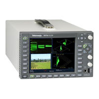
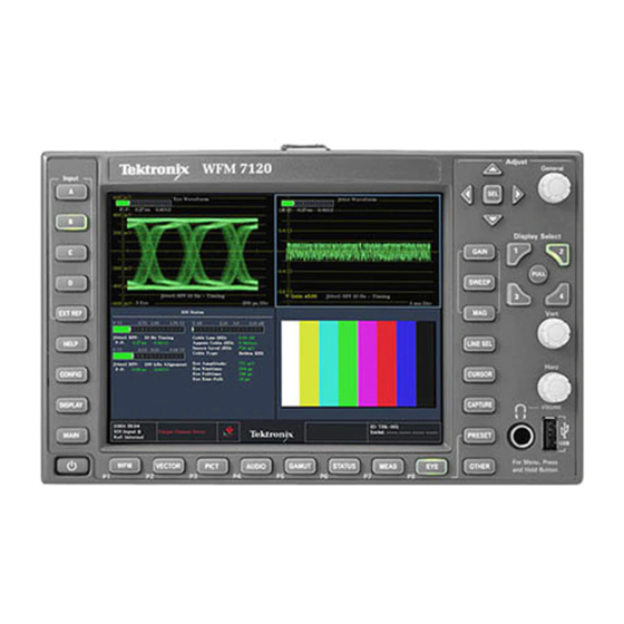
Tektronix WFM6120 Manuals
Manuals and User Guides for Tektronix WFM6120. We have
5
Tektronix WFM6120 manuals available for free PDF download: Quick Start User Manual, Technical Reference, Service Manual, Security Instructions, Release Notes
Tektronix WFM6120 Quick Start User Manual (164 pages)
Waveform monitors
Brand:
Tektronix
| Category:
Monitor
| Size: 6 MB
Table of Contents
Contacting Tektronix
4
Table of Contents
7
General Safety Summary
9
Compliance Information
11
EMC Compliance
11
Safety Compliance
13
Environmental Considerations
15
Preface
16
Key Features
16
Instrument Options
18
Where to Find more Information
21
Conventions Used in this Manual
21
Installation
23
Before Installation
23
Connecting Power and Powering On/Off
24
Installing in a Video System
25
Getting Acquainted with Your Instrument
27
Instrument Display
27
Front-Panel Controls
31
Rear-Panel Connectors
33
Power Requirements
34
Ethernet Connector
41
Selecting a Measurement
42
Setting Measurement Parameters
43
Selecting Signal Inputs
44
Gb/S Input Monitoring
45
Dual Link Input Monitoring
47
Simultaneous Input Monitoring
48
Measuring Audio/Video Delay
51
Setting Gain, Sweep, and Magnification
52
Using Presets
53
Measuring Waveforms with Cursors
54
Capturing the Display
56
Setting Line Select Mode
59
Configuring Your Instrument
60
Using Online Help
61
To Adjust Headphone Volume and Source
63
To Connect Directly to a PC
63
Checking Chroma/Luma Delay (Lightning Display)
64
Checking Gamut
66
Setup for Gamut Checks
66
Checking RGB Gamut
67
Checking Composite Gamut
69
Checking Luma Gamut
71
Automating Gamut Checks
72
Adjusting Gamut Limits
73
Monitoring Black Levels and Frozen Frames
74
Configuring Black Detect
74
Configuring Frozen Detect
76
Monitoring the SDI Physical Layer
78
Display Types
78
Configuring Physical Layer Settings (Options EYE and PHY)
79
Configuring Physical Layer Settings (Option 3G or JIT)
85
Taking Eye Measurements
87
Taking Jitter Measurements
92
Taking Cable Loss Measurements
96
Using the ARIB Displays
97
ARIB Status
98
ARIB STD-B.39 Display
99
ARIB STD-B.37 Display and Status Screens
101
ARIB STD-B.35 Display and Status Screens
103
ARIB TR-B.23 (1) Display and Status Screens
104
ARIB TR-B.23 (2) Display and Status Screens
106
ARIB TR-B.22 Display and Status Screens
107
Monitoring Audio
109
Configuring Audio Inputs
109
Selecting Audio Input
111
Checking Audio Level & Phase
111
Checking Audio Loudness
115
Checking Surround Sound
118
Configuring Audio Inputs for Embedded 16-Channel Audio
122
Selecting Audio Input for Embedded 16-Channel Audio
123
Quick Selection of 1-8 or 9-16 Channels of Embedded Audio
124
Monitor Dolby-Based Surround Sound
125
Configuring Dolby Inputs
125
Displaying Dolby Inputs
132
Viewing Dolby Metadata
133
Usage Notes
133
Monitoring Closed Captioning (CC), Teletext, AFD, and Safe Area Compliance
138
Monitoring Closed Captioning and Teletext
138
Monitoring for Safe Area Compliance
143
Monitoring for AFD Compliance
145
Monitoring for User-Defined ANC Data Types
146
Using Alarms
148
Configuring Alarms
148
Monitoring Alarms
152
Application Example
153
Timing a Studio
153
Upgrading Instrument Software
159
Advertisement
Tektronix WFM6120 Technical Reference (152 pages)
Waveform Monitors Specifications and Performance Verification
Brand:
Tektronix
| Category:
Monitor
| Size: 2 MB
Table of Contents
Table of Contents
7
General Safety Summary
11
Environmental Considerations
13
Preface
15
Related User Documents
15
Related Reference Documents
15
Specifications
17
Electrical Specifications
17
Table 1: SDI Input Waveform Vertical Characteristics
17
Table 2: Composite Analog Input Waveform Vertical Characteristics
19
Table 3: Composite Analog Inputs a and B Physical Layer
19
Table 4: Waveform Sweep (Horizontal) Deflection
20
Table 5: Eye Pattern Display
21
Table 6: Jitter Display (Option EYE and PHY)
23
Table 7: Jitter Display (Option JIT)
26
Table 8: Component Vector Mode
27
Table 9: Waveform Mode Filter Characteristics
28
Table 10: SDI Lightning and Diamond Modes
29
Table 11: Data Mode
29
Table 12: Composite Vector Mode
29
Table 13: Arrowhead Mode (NTSC/PAL Composite Limit Display)
30
Table 14: Bowtie Mode
30
Table 15: Timing Display
30
Table 16: Picture Mode
31
Table 17: Signal Level / Cable Length Detector
32
Table 18: Data Error Detection (EDH / Status, under STATUS Button)
33
Table 19: ANC Data and ARIB
33
Table 20: Audio Bar Displays
33
Table 21: Audio Bar and Lissajous/Surround Display
36
Table 22: AV Delay Display (Option AVD)
37
Table 23: AES Audio Inputs
37
Table 24: AES Audio Outputs (Alternate Function on Second Set of Inputs)
38
Table 25: Embedded Audio Extraction
39
Table 26: Analog Audio Inputs
40
Table 27: Analog Audio Outputs
41
Table 28: Dolby Digital (AC-3) Compressed Audio Monitoring (Opt. DDE)
42
Table 29: Dolby E and Extended Dolby Digital (AC-3) Compressed Audio Monitoring (Opt. DDE)
43
Table 30: Picture Monitor Outputs (VGA Pix Mon)
43
Table 31: LCD Display
44
Table 32: External XGA Output (EXT DISPLAY)
44
Table 33: LTC Time Code Input / Ground Closures
45
Table 34: VITC Decoding
46
Table 35: Serial Digital Video Interface (Input A, Input B)
46
Table 36: Serial Video Output (Serial Out/Sdi Pixmon)
47
Table 37: External Reference
48
Table 38: Ethernet
49
Table 41: Power Source
50
Physical Specifications
51
Supported Input Formats and Allowed References
52
Table 47: 24 Hz, 30 Hz, and 60 Hz Frame and Field Rates
53
Alarms
54
Table 50: HD SpecifiC Alarms (WFM7120, WFM7020 Opt. HD)
56
Table 54: Additional Audio Alarms (Opt. DDE)
57
Performance Verification
59
Test Records
60
Test Record - Function Tests
60
Test Record - All Instruments
62
Test Record - All Instruments (SD)
63
Test Record - Option CPS
64
Test Record - Options AD and DDE
65
Test Record - Option DS
71
Incoming Inspection
74
Required Equipment
74
Incoming Inspection Tests
76
Table 62: LCD Visual Defects
78
Table 63: Diagnostics Limits
80
Video and General Performance Verification Procedures
97
Required Equipment
97
Instrument Tests
99
Figure 1: VM5000 HD Frequency Response Display
103
Figure 2: Wiring Diagram for LTC Input/Ground Closure Cable
110
SD Video Tests
114
Figure 3: VM5000 SD Frequency Response Display
117
Table 65: Oscilloscope Settings for Serial Output Amplitude
120
Figure 4: Trigger Polarity Positive
121
Figure 5: Trigger Polarity Negative
122
Tests for Instruments with Option CPS
126
Signal Source Characterization for Eye Signal Bandwidth
134
Table 66: Generator Characterization
135
Audio Performance Verification Procedures
136
Required Equipment
136
Tests for Waveform Monitors Equipped with Audio Options
137
Additional Tests for Instruments Equipped with Options AD and DDE
145
Tektronix WFM6120 Service Manual (95 pages)
Waveform monitors
Brand:
Tektronix
| Category:
Monitor
| Size: 7 MB
Table of Contents
Service Manual
3
Table of Contents
7
General Safety Summary
11
Service Safety Summary
13
Preface
15
Manual Conventions
15
Related Manuals
16
Table I: Related Documentation
16
Introduction
17
Introduction
17
Service Strategy
19
Specifications
19
Performance Verification
19
Options and Accessories
19
Configurations
19
Hardware Installation
20
Product Upgrade
20
Operating Information
20
Theoryofoperation
21
Theory of Operation
21
Figure 2-1: Main Block Diagram
24
Main Board
25
Audio Options AD and DDE
26
Composite Input Option CPS
26
Front Panel
26
Option EYE/PHY
27
Figure 2-2: Option EYE/PHY Block Diagram
29
Option 3G/JIT
30
Figure 2-3: Option 3G/JIT Block Diagram
31
Fan Control
32
Power Supply and Distribution
32
Adjustment Procedures
33
Adjustments
35
Required Equipment
35
Procedures
35
Maintenance
41
General Maintenance
43
Preventing ESD
43
Inspection and Cleaning
44
Table 4-1: External Inspection Checklist
45
Table 4-2: Internal Inspection Checklist
45
Troubleshooting
47
Table 4-3: Required Test Equipment
48
Table 4-4: Symptoms and Causes
49
Detailed Troubleshooting Procedures
55
Table 4-5: Main Board Secondary Supplies
57
Table 4-6: Audio Main Board Secondary Supplies
57
Table 4-7: Analog Audio Secondary Supplies (Board Not Present for Option DS Instrument)
58
Table 4-8: Advanced Diagnostic Measurements
62
Figure 4-1: Main Board Power Supply Test Points and Leds
66
Figure 4-2: Audio Main Board Power Supply Test Point Locations
67
Figure 4-3: Analog Audio Board Power Supply Test Point Locations
68
Removal and Replacement Procedures
69
Preparation
69
Table 4-9: Tools Required for Module Removal
69
Module Removal
70
Table 4-10: Module Removal
70
Figure 4-4: Module Securing Screws
72
Figure 4-5: Front Panel Cable Connections
75
Figure 4-6: Front Panel Disassembly
76
Figure 4-7: LCD Assembly Bracket and Backlight Lock
77
Figure 4-8: Backlight Removal (B030000 and Above)
78
Repackaging Instructions
80
Packaging
80
Shipping to the Service Center
80
Replac
81
Replaceable Parts
81
Parts Ordering Information
83
Using the Replaceable Parts Lists
84
Table 5-1: Circuit Boards and Connectors (See Figure 5-1.)
84
Figure 5-1: Circuit Boards and Connectors
87
Table 5-2: Chassis Components (B030000 and Above) (See Figure 5-2.)
88
Figure 5-2: Chassis Components (B030000 and Above)
89
Table 5-3: Chassis Components (B029999 and Below) (See Figure 5-3.)
90
Figure 5-3: Chassis Components (B029999 and Below)
91
Table 5-4: Replaceable Parts List (See Figure 5-4.)
92
Figure 5-4: Main Board Replaceable Components
93
Figure 5-5: Analog Audio Breakout Cable Assembly
94
Table 5-5: Replaceable Parts List (See Figure 5-5.)
94
Table 5-6: Accessories
95
Advertisement
Tektronix WFM6120 Release Notes (9 pages)
Waveform Monitor
Brand:
Tektronix
| Category:
Monitor
| Size: 0 MB
Table of Contents
Release Notes
3
Known Issues and Behaviors
3
3 Gbps Pathogenic Signal
3
Anc Data Inspector
3
Audio Board Temperature
3
Audio Errors
3
Calibration and Performance Verification
4
Display Distortion
4
Capture and Freeze
4
Dolby Bar Labels
4
Dolby Operation with Option DDE
5
Dual Link Mode
5
Embedded Audio Active Bits (SD Only)
5
Embedded Audio with 3 Gbps Level a Signals (1080 50P/59.94P/60P)
6
Error Readouts
6
External Reference
6
Field Installs of Dolby Options
6
1080 50P, 1080 59.94P, and 1080 60P Formats
7
Incompatible Operation
7
OP47 Teletext
7
Print
7
SDI Status Display
7
Simultaneous Input Mode (Option SIM)
7
SNMP Messages
8
Sweep
8
Sweep MAG
8
Usb
8
Waveform Mode Cursor for XYZ Color Space
8
Web Browser
8
Tektronix WFM6120 Security Instructions (11 pages)
Waveform monitors
Brand:
Tektronix
| Category:
Monitor
| Size: 0 MB
Table of Contents
Table of Contents
3
Preface
5
Clear and Sanitize Procedures
7
Memory Devices
7
Data Export Devices
10
Troubleshooting
11
How to Clear or Sanitize a Non-Functional Instrument
11
How to Recover from Clearing or Removing the Instrument's Memory
11
Advertisement
Related Products
Tektronix WFM601
Tektronix WFM6100 Opt. MB
Tektronix WFM 601i
Tektronix WFM61UP FP
Tektronix WFM 601A
Tektronix WFM 601E
Tektronix WFM91D
Tektronix WFM71UP FP
Tektronix WFM5250
Tektronix WFM8300
Tektronix Categories
Test Equipment
Measuring Instruments
Amplifier
Portable Generator
Printer
More Tektronix Manuals
Login
Sign In
OR
Sign in with Facebook
Sign in with Google
Upload manual
Upload from disk
Upload from URL