Tektronix WFM6100 Technical Reference
Waveform monitors system integration
Hide thumbs
Also See for WFM6100:
- Technical reference (174 pages) ,
- Quick start user manual (149 pages) ,
- Service manual (76 pages)
Table of Contents
Advertisement
Quick Links
Technical Reference
WFM6100, WFM7000, and WFM7100
Waveform Monitors
System Integration
071-1983-00
Warning
The servicing instructions are for use by qualified
personnel only. To avoid personal injury, do not
perform any servicing unless you are qualified to
do so. Refer to all safety summaries prior to
performing service.
www.tektronix.com
Advertisement
Table of Contents

Related Manuals for Tektronix WFM6100


Summary of Contents for Tektronix WFM6100
- Page 1 Technical Reference WFM6100, WFM7000, and WFM7100 Waveform Monitors System Integration 071-1983-00 Warning The servicing instructions are for use by qualified personnel only. To avoid personal injury, do not perform any servicing unless you are qualified to do so. Refer to all safety summaries prior to performing service.
- Page 2 Copyright © Tektronix. All rights reserved. Licensed software products are owned by Tektronix or its subsidiaries or suppliers, and are protected by national copyright laws and international treaty provisions. Tektronix products are covered by U.S. and foreign patents, issued and pending. Information in this publication supercedes that in all previously published material.
- Page 3 ..........WFM6100, WFM7000, and WFM7100 Waveform Monitors...
- Page 4 Table of Contents WFM6100, WFM7000, and WFM7100 Waveform Monitors...
-
Page 5: General Safety Summary
Do Not Operate in Wet/Damp Conditions. Do Not Operate in an Explosive Atmosphere. Keep Product Surfaces Clean and Dry. Provide Proper Ventilation. Refer to the manual’s installation instructions for details on installing the product so it has proper ventilation. WFM6100, WFM7000, and WFM7100 Waveform Monitors... - Page 6 WARNING indicates an injury hazard not immediately accessible as you read the marking. CAUTION indicates a hazard to property including the product. Symbols on the Product. The following symbols may appear on the product: CAUTION WARNING Protective Ground Refer to Manual High Voltage (Earth) Terminal WFM6100, WFM7000, and WFM7100 Waveform Monitors...
-
Page 7: Service Safety Summary
Use Care When Servicing With Power On. Dangerous voltages or currents may exist in this product. Disconnect power, remove battery (if applicable), and disconnect test leads before removing protective panels, soldering, or replacing components. To avoid electric shock, do not touch exposed connections. WFM6100, WFM7000, and WFM7100 Waveform Monitors... - Page 8 Service Safety Summary WFM6100, WFM7000, and WFM7100 Waveform Monitors...
-
Page 9: Related User Documents
(Tektronix part number 071-1895-XX). This document describes any known problems or behaviors that you might encounter while using the waveform monitor. H WFM6100, WFM7000, and WFM7100 Waveform Monitors Quick Start User Manual (Tektronix part numbers: English, 020-2705-XX; Japanese, 020-2706-XX; Simplified Chinese, 020-2707-XX). This document is a printed Quick Start User Manual and contains the basic operating informa- tion for the instrument. -
Page 10: Related Reference Documents
Preface Related Reference Documents The following related reference documents are available at the Tektronix Web site (www.tektronix.com): H Preventing Illegal Colors. This application note describes how the Diamond, Arrowhead, and Lightning displays can be used to help prevent the undesired impact of color gamut violations and to simplify the assessment of proper gamut compliance. -
Page 11: System Integration
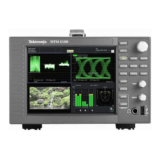
System Integration The WFM6100, WFM7000, and WFM7100 Waveform Monitors offer the monitoring capabilities needed in the production, post-production, distribution, and transmission of high-definition (HD) and standard-definition (SD) digital video content. With available digital audio monitoring support, you can expand the capabilities to monitor both digital video and audio in a single instrument. - Page 12 Figure 1: Front panel NOTE. You can locate copies of some of the illustrations from this document in JPEG format on the Tektronix Web site (www.tektronix.com) and on the User Documents CD that accompanies the WFM6100, WFM7000, and WFM7100 Quick Start User Manual.
- Page 13 System Integration Figure 2: Rear panel with neither Option EYE nor PHY installed WFM6100, WFM7000, and WFM7100 Waveform Monitors...
- Page 14 System Integration Figure 3: Rear panel with Option EYE or PHY installed WFM6100, WFM7000, and WFM7100 Waveform Monitors...
-
Page 15: Installation Considerations
The waveform monitor does not need any power configuration, except for using the proper power cord for your installation site. Refer to the WFM6100, WFM7000, and WFM7100 Waveform Monitors Quick Start User Manual for a list of the available power cords. - Page 16 System Integration The following table lists the power and environmental specifications for installing the waveform monitor. Refer to the WFM6100, WFM7000, and WFM7100 Waveform Monitors Specifications and Performance Verification Technical Reference for additional information on power and environmental requirements. Table 2: Power and environmental specifications...
-
Page 17: Connector Specifications
- - 6.0 V to +6.0 V, DC + peak AC External Reference BNC, passive loop through 75 Ω compensated Input Type Input Level - - 6 to +6 dB Maximum Operating Input Voltage 5 V, DC WFM6100, WFM7000, and WFM7100 Waveform Monitors... - Page 18 TTL thresholds, 5 V max input, - - 0.5 min input; pull low to assert Ground Closure Output Signal One open collector output Ethernet RJ-45 LAN supporting 10/100 BaseT; supports manual and DHCP address modes WFM6100, WFM7000, and WFM7100 Waveform Monitors...
-
Page 19: Connector Pin Assignments
Balanced differential analog audio input; Ch. 4, line B, positive Balanced differential analog audio input; Ch. 5, line A, positive Balanced differential analog audio input; Ch. 5, line B, positive Balanced differential analog audio input; Ch. 6, line A, positive WFM6100, WFM7000, and WFM7100 Waveform Monitors... - Page 20 Balanced differential analog audio output; Ch. 5, negative Balanced differential analog audio output; Ch. 6, negative Balanced differential analog audio output; Ch. 7, negative Balanced differential analog audio output; Ch. 8, negative 43 - - 62 Not used WFM6100, WFM7000, and WFM7100 Waveform Monitors...
- Page 21 Figure 5: Ethernet connector pin numbering Table 6: Ethernet connector pin assignments Pin/LED Name Description TX_D1+ Transceive Data+ TX_D1- - Transceive Data- - RX_D2+ Receive Data+ Not used Not used RX_D2- - Receive Data- - Not used Not used WFM6100, WFM7000, and WFM7100 Waveform Monitors...
- Page 22 Ground this pin to select preset 1 Preset Recall 2 Ground this pin to select preset 2 Preset Recall 3 Ground this pin to select preset 3 Preset Recall 4 Ground this pin to select preset 4 WFM6100, WFM7000, and WFM7100 Waveform Monitors...
- Page 23 Table 8: External Display connector pin assignments Description Red output Green output Blue output Not used Ground Ground Ground Ground Not used Ground Not used Not used/SDA Horizontal sync output Vertical sync output Not used/SCL WFM6100, WFM7000, and WFM7100 Waveform Monitors...
- Page 24 Table 9: Picture Monitor connector pin assignments Description Red output Green output Blue output Not used Ground Ground Ground Ground Not used Ground Not used Not used Horizontal sync output Vertical sync output Not used WFM6100, WFM7000, and WFM7100 Waveform Monitors...
-
Page 25: Rackmount Installation
You can also install a sleeve in one side of the rack adapter and a blank panel (1700F06) or an accessory drawer (1700F07) in the other side of the adapter to improve airflow and appearance. WFM6100, WFM7000, and WFM7100 Waveform Monitors... - Page 26 System Integration Figure 9: WFM7F05 exploded view WFM6100, WFM7000, and WFM7100 Waveform Monitors...
- Page 27 15.87 mm (.625 in) 9.53 mm (.375 in) 25.40 mm 38.10 mm (1.000 in) 53.98 mm (1.500 in) 63.50 mm (2.125 in) (2.500 in) 17.86 mm (.703 in) Figure 10: WFM7F05 rear-bracket guide dimensions WFM6100, WFM7000, and WFM7100 Waveform Monitors...
- Page 28 126.37 mm Rear Rear (4.965 in) (4.975 in) 209.55 mm 209.55 mm (8.250 in) (8.250 in) 407.67 mm 410.21 mm (16.050 in) (16.150 in) Bottom Bottom WFM7FOO sleeve 1700FOOA sleeve Figure 12: WFM7F05 sleeve dimensions WFM6100, WFM7000, and WFM7100 Waveform Monitors...
- Page 29 Directional mark Sleeve release button (one on each side) To adjust the WFM7F05 Rack Adapter, attach the handle bracket using one of the three settings shown below. Figure 13: Adjusting the position of the handles WFM6100, WFM7000, and WFM7100 Waveform Monitors...
-
Page 30: System Installation
To monitoring the video bitstream of a serial receiver, route the incoming serial signal into one of the waveform monitor SDI inputs. NOTE. Refer to the WFM6100, WFM7000, and WFM7100 Specifications and Performance Verification Technical Reference for the maximum cable lengths allowed for the input signal. -
Page 31: Network Operation
(Be sure to use compatible addresses between the PC and the waveform monitor.) 6. If desired, touch Instrument Name to assign the waveform monitor a network name. 7. Press the MAIN button to close the menu. WFM6100, WFM7000, and WFM7100 Waveform Monitors... - Page 32 NOTE. The SNMP commands are contained in a MIB (Management Information Base). Refer to the WFM Series Waveform Monitors and WVR Series Waveform Rasterizers Management Information Base Technical Reference (Tektronix part number 071-1592-XX) for information about using the MIB to control the waveform monitor.
- Page 33 For example, the IP address 124.161.038.092 should be entered as follows: 124.161.38.92. 7. The Web browser will display the remote interface for the waveform monitor. To make a selection, click the desired link. WFM6100, WFM7000, and WFM7100 Waveform Monitors...
- Page 34 System Integration WFM6100, WFM7000, and WFM7100 Waveform Monitors...
Need help?
Do you have a question about the WFM6100 and is the answer not in the manual?
Questions and answers