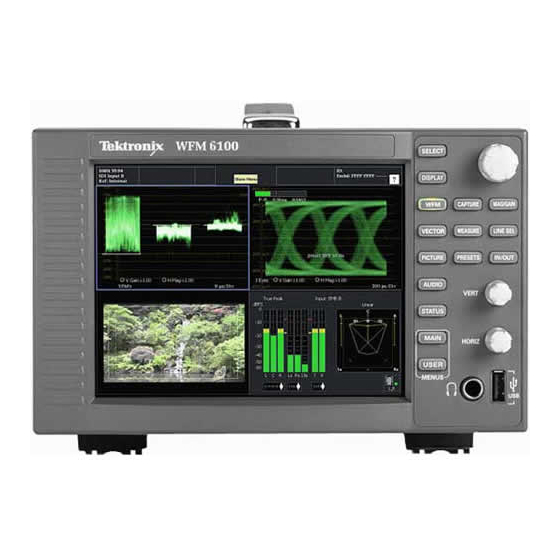
Tektronix WFM6100 Quick Start User Manual
Waveform monitors with option fp
Hide thumbs
Also See for WFM6100:
- Technical reference (174 pages) ,
- Quick start user manual (149 pages) ,
- Service manual (76 pages)

Related Manuals for Tektronix WFM6100


Summary of Contents for Tektronix WFM6100
- Page 1 WFM6100, WFM7000, and WFM7100 Waveform Monitors With Option FP Quick Start User Manual www.tektronix.com 071-2288-00...
-
Page 2: Contacting Tektronix
Copyright © Tektronix. All rights reserved. Licensed software products are owned by Tektronix or its subsidiaries or suppliers, and are protected by national copyright laws and international treaty provisions. Tektronix products are covered by U.S. and foreign patents, issued and pending. Information in this publication supersedes that in all previously published material. - Page 3 Warranty 2 Tektronix warrants that this product will be free from defects in materials and workmanship for a period of one (1) year from the date of shipment. If any such product proves defective during this warranty period, Tektronix, at its option, either will repair the defective product without charge for parts and labor, or will provide a replacement in exchange for the defective product.
-
Page 5: Table Of Contents
Taking Eye Measurements...................... WFM6100, WFM7000, and WFM7100 With Option FP Quick Start User Manual... - Page 6 Specifications ........................Index WFM6100, WFM7000, and WFM7100 With Option FP Quick Start User Manual...
-
Page 7: General Safety Summary
If you suspect that there is damage to this product, have it inspected by qualified service personnel. Avoid Exposed Circuitry. Do not touch exposed connections and components when power is present. WFM6100, WFM7000, and WFM7100 With Option FP Quick Start User Manual... - Page 8 WARNING indicates an injury hazard not immediately accessible as you read the marking. CAUTION indicates a hazard to property including the product. The following symbol(s) may appear on the product: WFM6100, WFM7000, and WFM7100 With Option FP Quick Start User Manual...
-
Page 9: Environmental Considerations
This product has been classified as Monitoring and Control equipment, and is outside the scope of the 2002/95/EC RoHS Directive. This product is known to contain lead, cadmium, mercury, and hexavalent chromium. WFM6100, WFM7000, and WFM7100 With Option FP Quick Start User Manual... -
Page 10: Preface
WFM7100 with Option FP Key Features Tektronix waveform monitors can help you monitor and measure SD SDI, HD SDI, and/or composite analog signals. All instrument models come standard with SD SDI input monitoring capabilities. The following table includes key features available on standard equipped instruments. - Page 11 Error tracking Configurable alarms and error logging. Remote control Full remote control for complete installation flexibility. WFM6100, WFM7000, and WFM7100 With Option FP Quick Start User Manual...
-
Page 12: Instrument Options
Adds support for Audio/Video delay (AVD) measurement. WFM6100 WFM7100 Adds datalist (DAT) analysis capabilities and allows for logic-level view of video and audio digital data stream and WFM6100 ANC data extraction. viii WFM6100, WFM7000, and WFM7100 With Option FP Quick Start User Manual... - Page 13 Option D5. Adds 5 years of Calibration Data Report (when ordered with option C5). Option R3. Adds 3 years of Repair Service (including the period under warranty). Option R5. Adds 5 years of Repair Service (including period under warranty). WFM6100, WFM7000, and WFM7100 With Option FP Quick Start User Manual...
-
Page 14: Where To Find More Information
Service Manual Optional manual supporting module-level servicing of the instrument Conventions Used in this Manual The following icons are used throughout this manual: Sequence Step Connect power Network WFM6100, WFM7000, and WFM7100 With Option FP Quick Start User Manual... -
Page 15: Installation
(including the anti-static bag) in case you need to ship the instrument. Accessories The table below shows which items are standard accessories and which items are optional accessories. Check the Tektronix Web site (www.tektronix.com) for the most current information on accessories. -
Page 16: Connecting Power And Powering On/Off
WFM7100 series, 1700 Series, WFM601 series, WFM700 series, 760A, and 764. Each half of the rack can be ordered as either Option O or Option N. Option N is used for WFM700, WFM6100 series, WFM7000 series, and WFM7100 series monitors. Option O is used for 1700 Series, WFM601 Series, 760A and 764 instruments. -
Page 17: Installing The Monitor In A Video System
1. Route the incoming serial signal into one of the instrument SDI inputs. NOTE. See the Specifications in the Specifications and Performance Verification manual for maximum allowed cable lengths. Option Eye/Phy SD and Option HD WFM6100, WFM7000, and WFM7100 With Option FP Quick Start User Manual... - Page 18 The termination must be 75 Ω and DC coupled (good return loss extends to DC). An appropriate termination would be Tektronix part number 011-0102-00. It is a 75 Ω, End of Line termination. Compatibility of BNC Center Pins Most video equipment BNC connectors, whether 50 Ω...
-
Page 19: Getting Acquainted With Your Instrument
Note that the button you select lights and that a light-blue outline surrounds the tile. Both the lit button and the light-blue outline indicate the active, selected tile. Tile 4 is shown selected here. WFM6100, WFM7000, and WFM7100 With Option FP Quick Start User Manual... - Page 20 4. To select another tile, just push its button. The tile you select will replace the previously selected tile, displaying full screen. 5. Push the FULL button again to toggle to the four-tile display. WFM6100, WFM7000, and WFM7100 With Option FP Quick Start User Manual...
- Page 21 A 16-character string indicating the selected audio input or the embedded audio channel status, when embedded audio is the selected input, In the latter case, each character shows the status of a specific channel:- for not present and p for present. WFM6100, WFM7000, and WFM7100 With Option FP Quick Start User Manual...
- Page 22 Text indicating the selected input. Possible inputs are: SDI A, SDI B, Cmpst A, Cmpst B (depending on installed options). Also indicates if the current input is not in Auto mode and is unlocked. WFM6100, WFM7000, and WFM7100 With Option FP Quick Start User Manual...
-
Page 23: Front-Panel Controls
Instrument-wide settings. The parameters in the Configuration menu are instrument-wide settings. The configuration menu controls settings that are changed only occasionally, such as changing waveform color or setting the network address. WFM6100, WFM7000, and WFM7100 With Option FP Quick Start User Manual... - Page 24 Configuring Your Instrument (See page 34.) Up/Down/Left/Right Arrow keys and SEL Button Demonstrated in Setting Measurement Parameters (See page 20.) General Knob Demonstrated in Selecting/Adjusting a Parameter (See page 34.) WFM6100, WFM7000, and WFM7100 With Option FP Quick Start User Manual...
-
Page 25: Rear-Panel Connectors
The following figures shows the rear panel with optional connectors. Instruments without Options EYE or PHY have the SDI inputs located along the bottom-right portion of the rear panel. Instruments with Option EYE or PHY have the SDI inputs arranged vertically. Options SD/HD Options Eye/Phy WFM6100, WFM7000, and WFM7100 With Option FP Quick Start User Manual... -
Page 26: Power Requirements
75 Ω and require termination. 1. Ref Loop. A synchronization input. The input signal can be analog black burst, analog composite video, or analog tri-level for HD. Requires termination. WFM6100, WFM7000, and WFM7100 With Option FP Quick Start User Manual... - Page 27 SDI input. 5. Clock Out Recovered clock output. Options Eye/Phy only. Option Eye/Phy Option SD/HD CMPST A and CMPST B composite inputs. Option CPS WFM6100, WFM7000, and WFM7100 With Option FP Quick Start User Manual...
- Page 28 Balanced differential analog audio input- Ch. 4, line A, positive. 8 ANALOG_INPUT_B4_P Balanced differential analog audio input- Ch. 4, line B, positive. 9 ANALOG_INPUT_A5_P Balanced differential analog audio input- Ch. 5, line A, positive. WFM6100, WFM7000, and WFM7100 With Option FP Quick Start User Manual...
- Page 29 Balanced differential analog audio output- Ch. 6, negative. 40 ANALOG_OUTPUT_6_N 41 ANALOG_OUTPUT_7_N Balanced differential analog audio output- Ch. 7, negative. 42 ANALOG_OUTPUT_8_N Balanced differential analog audio output- Ch. 8, negative. 43—62 No connection. WFM6100, WFM7000, and WFM7100 With Option FP Quick Start User Manual...
- Page 30 Green Video Blue Video Not connected Ground Red Ground Green Ground Blue Ground +5 V (for monitor EEPROM) Not Connected Not Connected ID Bit Horizontal Sync Vertical Sync ID Clock WFM6100, WFM7000, and WFM7100 With Option FP Quick Start User Manual...
- Page 31 NOTE. For more information on Preset recall, refer to the User Technical Reference manual on the User Documentation CD that was shipped with your instrument. WFM6100, WFM7000, and WFM7100 With Option FP Quick Start User Manual...
-
Page 32: Ethernet Connector
0011 Preset 3 0010 Preset 2 0001 Preset 1 0000 Unused Ethernet Connector The instrument provides a 10/100 BaseT Ethernet interface. The Ethernet connector is a standard RJ-45 connector. WFM6100, WFM7000, and WFM7100 With Option FP Quick Start User Manual... -
Page 33: Selecting A Measurement
SDI signal, including jitter (operation requires Option EYE) 3. Repeat steps 1 and 2 until you have selected measurement displays for all tiles that you want to define. WFM6100, WFM7000, and WFM7100 With Option FP Quick Start User Manual... -
Page 34: Setting Measurement Parameters
2. Push and hold the tile button for the measurement that you displayed in step 1. 3. When the menu pops up, navigate it and make your selections as described in the steps that follow. WFM6100, WFM7000, and WFM7100 With Option FP Quick Start User Manual... -
Page 35: Selecting Signal Inputs
Instruments with SD only: Connect SD signal only. NOTE. The A and B inputs are separate inputs and cannot be used as a loop-through path. Option Eye/Phy Option SD/HD WFM6100, WFM7000, and WFM7100 With Option FP Quick Start User Manual... -
Page 36: Dual Link Input Monitoring
Sample Structure from the SDI Input submenu of the Configuration menu. XYZ sample structures are not supported. 3. Select a tile and measurement in which to display the input. WFM6100, WFM7000, and WFM7100 With Option FP Quick Start User Manual... - Page 37 You can then view combined Link A, Link B, and Alpha Channel information, which can help with the identification of correct content. Alpha Channel information will be visible, if present. The next image illustrates where this information appears in the waveform. WFM6100, WFM7000, and WFM7100 With Option FP Quick Start User Manual...
-
Page 38: Simultaneous Input Monitoring
4. Press the CONFIG button, select Input Mode, press SEL, and then press the right arrow key to select Simultaneous. WFM6100, WFM7000, and WFM7100 With Option FP Quick Start User Manual... - Page 39 The images to the right are examples configurations. NOTE. The status bar at the bottom of the screen shows which side of the display is associated with which link. WFM6100, WFM7000, and WFM7100 With Option FP Quick Start User Manual...
-
Page 40: Measuring Audio/Video Delay
Getting Acquainted With Your Instrument Measuring Audio/Video Delay When the appropriate A/V Delay sequence is provided (from a Tektronix TG700 signal generator, for example), instruments with Option AVD provide measurement of audio/video delay with a numeric readout and graphical display. This capability is useful for facility maintenance and setup applications because it allows for out of service testing to quickly ensure synchronization across a facility. -
Page 41: Setting Gain, Sweep, And Magnification
1. Press and hold the Sweep button. 2. Select the sweep setting that you want. To Set Magnification 1. Press and hold the MAG button. 2. Select the magnification setting that you want. WFM6100, WFM7000, and WFM7100 With Option FP Quick Start User Manual... -
Page 42: Using Presets
4. Press the PRESET button and then press the numbered button for the preset you want to recall. The front panel setup will switch to the saved preset corresponding to the button pressed. WFM6100, WFM7000, and WFM7100 With Option FP Quick Start User Manual... -
Page 43: Measuring Waveforms With Cursors
To quickly center the active cursor on screen, press and hold the SEL button. 5. Repeat steps 3 and 4 to adjust the other cursor. 6. Read the cursor measurement in the Cursors readout. WFM6100, WFM7000, and WFM7100 With Option FP Quick Start User Manual... - Page 44 Time – display the position of each cursor relative to the start of the sweep and the difference between the two cursors. Voltage + Time – displays both the Voltage and Time cursors. WFM6100, WFM7000, and WFM7100 With Option FP Quick Start User Manual...
-
Page 45: Capturing The Display
For waveform displays, the captured image is shown in a different color to distinguish it from the live image. For all displays, the instrument continues to log error status in the background while the display is captured. WFM6100, WFM7000, and WFM7100 With Option FP Quick Start User Manual... - Page 46 Delete Image (Clear) will already be selected. 3. Press SEL to delete the frozen image. The pop-up menu is automatically removed from the display when the frozen image is deleted. WFM6100, WFM7000, and WFM7100 With Option FP Quick Start User Manual...
-
Page 47: Setting Line Select Mode
(field 4), or All. 4. The line and field information will appear at the bottom of the display screen. 5. Turn the GENERAL knob to select the line you want to view. WFM6100, WFM7000, and WFM7100 With Option FP Quick Start User Manual... -
Page 48: Configuring Your Instrument
Context-sensitive. The topic displayed depends on what is displayed in the active tile when the online help is selected or what control is operated after help is selected. Navigable. The Contents and Topic Selector panes, along with Links within the topics, provide access to topics. WFM6100, WFM7000, and WFM7100 With Option FP Quick Start User Manual... - Page 49 / down arrow key. 3. Press SEL to jump to the linked-to topic. 4. Press the left-arrow key to go back to the previous topic. WFM6100, WFM7000, and WFM7100 With Option FP Quick Start User Manual...
-
Page 50: To Adjust Headphone Volume And Source
2. Use the Horizontal knob to adjust the volume. 3. Adjust the headphone source by pressing the AUDIO button, selecting Headphone Input, and then selecting the source you want. WFM6100, WFM7000, and WFM7100 With Option FP Quick Start User Manual... -
Page 51: To Connect Directly To A Pc
Manual IP mode and set the IP address manually. Be sure to set an address that is compatible with the setting of your PC. 3. Configure the SNMP setup, if used. WFM6100, WFM7000, and WFM7100 With Option FP Quick Start User Manual... -
Page 52: Checking Chroma/Luma Delay (Lightning Display)
7. Set BarTargets to match your input signal. 8. Select Center Waveform, and press SEL if you want center your waveform. 9. Press the VECT button to close the menu. WFM6100, WFM7000, and WFM7100 With Option FP Quick Start User Manual... - Page 53 1080p 50, 59.94, 60 (dual link Tic Mark SD Timing Error (ns) HD Timing Error (ns) formats) Timing Error (ns) 0 marks 13.5 6.75 13.5 Luma sample Chroma sample WFM6100, WFM7000, and WFM7100 With Option FP Quick Start User Manual...
-
Page 54: Checking Gamut
2. Select the input corresponding to the signal connected. 3. Select a tile. 4. Press and hold the GAMUT button to display the signal in a tile and pop up the GAMUT menu. WFM6100, WFM7000, and WFM7100 With Option FP Quick Start User Manual... -
Page 55: Checking Rgb Gamut
Errors in green amplitude affect both diamonds equally, while blue amplitude errors affect only the top diamond and red errors affect only the bottom diamond. WFM6100, WFM7000, and WFM7100 With Option FP Quick Start User Manual... - Page 56 To isolate gamut bright-ups, try the following: Use the LINE SEL button to select individual lines WFM6100, WFM7000, and WFM7100 With Option FP Quick Start User Manual...
-
Page 57: Checking Composite Gamut
NTSC and PAL Arrowhead displays (75% Color bars) and indicates the values of the graticule lines. The arrowhead shape of the graticule results from overlaying the standard limits for luminance and luminance-plus-peak chrominance. WFM6100, WFM7000, and WFM7100 With Option FP Quick Start User Manual... - Page 58 Usage Notes To adjust the IRE level limits, do the procedure Adjusting Gamut Limits. (See page 47.) To automate this check, do the procedure Automating Gamut Checks. (See page 46.) WFM6100, WFM7000, and WFM7100 With Option FP Quick Start User Manual...
-
Page 59: Checking Luma Gamut
Another useful Arrowhead function is a measure of how well the active video signal is using the dynamic range of the video channel. A properly adjusted signal should be centered in the arrowhead graticule and have transitions that approach all the limits. WFM6100, WFM7000, and WFM7100 With Option FP Quick Start User Manual... -
Page 60: Automating Gamut Checks
Alarms menu before leaving the Alarms menu. NOTE. For information on Alarms, press the HELP button while Alarms is selected in the configuration menu. 6. Press CONFIG to exit the menu. WFM6100, WFM7000, and WFM7100 With Option FP Quick Start User Manual... -
Page 61: Adjusting Gamut Limits
SEL button (and General knob, when indicated) to select and set the various thresholds. Note that you can also reset thresholds to defaults. WFM6100, WFM7000, and WFM7100 With Option FP Quick Start User Manual... -
Page 62: Monitoring The Sdi Physical Layer
For instruments with Option DL or SIM, your instrument can only monitor physical layer information on one input at a time. To make measurements, select the input you want to monitor and then proceed with the following steps. WFM6100, WFM7000, and WFM7100 With Option FP Quick Start User Manual... - Page 63 The Timing filter selection sets the filter value to 10 Hz. The Align filter selection sets the filter value to 1 kHz for SD or 100 kHz for HD. WFM6100, WFM7000, and WFM7100 With Option FP Quick Start User Manual...
- Page 64 Off. Enables the equalizer, which enables operation with typical cable lengths and reduces jitter due to cable effects. Use this setting for most signals. WFM6100, WFM7000, and WFM7100 With Option FP Quick Start User Manual...
- Page 65 22. Select Jitter2 Level. Use the General knob to increase or decrease the threshold level for the Jitter2 engine controlling the bottom two tiles of the waveform rasterizer display. WFM6100, WFM7000, and WFM7100 With Option FP Quick Start User Manual...
- Page 66 3000 ps (SD) or 1000 ps (HD); the minimum risetime is 0 ps. 30. Option PHY Only. Select Eye Risetime Min. Use the General knob to increase or decrease the setting. WFM6100, WFM7000, and WFM7100 With Option FP Quick Start User Manual...
- Page 67 38. Press SEL and set the response type for each of the Physical Layer alarms. (See page 102, Using Alarms.) NOTE. For instruments with Option DL and SIM, only the single, currently selected input will be monitored. WFM6100, WFM7000, and WFM7100 With Option FP Quick Start User Manual...
-
Page 68: Taking Eye Measurements
Similarly, the automatic risetime and falltime measurements use histograms to find the centers of the distributions of 20% and 80% crossings. The difference between manual and automatic measurements is usually insignificant for clean, symmetrical signals. WFM6100, WFM7000, and WFM7100 With Option FP Quick Start User Manual... - Page 69 5. Note the amplitude of the eye waveform that is displayed in the Voltage Cursor readout. NOTE. Signal-source amplitudes outside of ±10% of 800 mVp-p can degrade receiver performance. WFM6100, WFM7000, and WFM7100 With Option FP Quick Start User Manual...
- Page 70 Aberrations at the top or bottom line of the waveform should not exceed 10% of the signal amplitude. Automatic equalizer circuits in receivers may be sensitive to larger aberrations. WFM6100, WFM7000, and WFM7100 With Option FP Quick Start User Manual...
- Page 71 find the centers of the distributions of 20% and 80% crossings. The difference between manual and automatic measurements is usually insignificant for clean, symmetrical signals. WFM6100, WFM7000, and WFM7100 With Option FP Quick Start User Manual...
- Page 72 3. Press and hold the STATUS button to display the pop-up menu. 4. Select Display Type and then select SDI Status. 5. Note the Eye waveform measurements in the SDI Status display readouts. WFM6100, WFM7000, and WFM7100 With Option FP Quick Start User Manual...
-
Page 73: Taking Jitter Measurements
Notice that there is no indication of jitter spikes. In the lower Eye display, the jitter is of a low-density haze, which suggests a less uniform jitter distribution. This is indicated by the spikes. WFM6100, WFM7000, and WFM7100 With Option FP Quick Start User Manual... - Page 74 Monitoring the SDI Physical Layer Figure 3: Measuring jitter WFM6100, WFM7000, and WFM7100 With Option FP Quick Start User Manual...
- Page 75 Timing filter. To measure alignment jitter, select the 1 kHz filter for SD signals or select the 100 kHz filter for HD signals, or select the Align filter. WFM6100, WFM7000, and WFM7100 With Option FP Quick Start User Manual...
-
Page 76: Taking Cable Loss Measurements
Therefore, the automatic Eye Amplitude measurement (Option PHY only) may be significantly less than the indicated Source Level. WFM6100, WFM7000, and WFM7100 With Option FP Quick Start User Manual... - Page 77 4. Use the arrow keys and the SEL button to select the SDI Status display. 5. Use the Cable Loss thermometer and readouts to monitor the cable loss. WFM6100, WFM7000, and WFM7100 With Option FP Quick Start User Manual...
-
Page 78: Using The Arib Displays
3. Select Aux Data Settings. 4. Select ARIB Content Display. 5. Select Enable to access the ARIB displays and alarms; or Disable to block access. WFM6100, WFM7000, and WFM7100 With Option FP Quick Start User Manual... -
Page 79: Arib Status
ARIB TR-B.23 (2) (guidelines for inter-stationary control data transport, group 2) ARIB TR-B.22 (guidelines for ancillary data transport) Additionally, the status of the following ITU standard is shown: ITU.R BT-1685 (inter-stationary Control Data conveyed by ancillary data packets) WFM6100, WFM7000, and WFM7100 With Option FP Quick Start User Manual... -
Page 80: Arib Std-B.39 Display
SDID - Secondary Data Identifier of the requested interstationary control packet; can be any of the following: ARIB specification - 0xFE ITU Specification - 0x01 Line - The line of the video (within the field) from which the packet was acquired. WFM6100, WFM7000, and WFM7100 With Option FP Quick Start User Manual... - Page 81 Status Bits (S8..S1 S16..S9) - 16 user-defined status bits. Error Correcting Code - A six-word, Reed-Solomon error correcting code, which is used to verify the integrity of the ARIB B.39 or ITU-R BT.1685 packet. WFM6100, WFM7000, and WFM7100 With Option FP Quick Start User Manual...
-
Page 82: Arib Std-B.37 Display And Status Screens
The decoded ancillary data includes the following: DID - Data Identifier of the requested closed captioning packet; can be any of the following: Analog signal - 0x5F SD Signal - 0x5 HD Signal - 0x5F WFM6100, WFM7000, and WFM7100 With Option FP Quick Start User Manual... - Page 83 Checksum - Indicates the checksum word that was recovered from the acquired packet. Placement - Can display either OK or ERROR, indicating whether the ARIB B.37 packets are present in the allowable configuration(s) specified in ARIB TR-B.23. WFM6100, WFM7000, and WFM7100 With Option FP Quick Start User Manual...
-
Page 84: Arib Std-B.35 Display And Status Screens
(with parity bits added) is displayed in parenthesis, in hexadecimal. Field - The field of the video from which the packet was acquired. For progressive formats, 1 is displayed. WFM6100, WFM7000, and WFM7100 With Option FP Quick Start User Manual... -
Page 85: Arib Tr-B.23 (1) Display And Status Screens
(1). (See Figure 8.) When this display is selected, the instrument searches the signal for ARIB TR-B.23 (1) packets using the DID/SDID combinations defined by ARIB. Figure 8: ARIB TR-B.23 (1) display (with the associated ARIB Status display) WFM6100, WFM7000, and WFM7100 With Option FP Quick Start User Manual... - Page 86 Format - Indicates the name of the ancillary data type or standard. User Data Words - Contains the payload of the ancillary packet, displayed in hexadecimal. All 10 bits are displayed. WFM6100, WFM7000, and WFM7100 With Option FP Quick Start User Manual...
-
Page 87: Arib Tr-B.23 (2) Display And Status Screens
(with parity bits added) is displayed in parenthesis, in hexadecimal. Field - The field of the video from which the packet was acquired. For progressive formats, 1 is displayed. WFM6100, WFM7000, and WFM7100 With Option FP Quick Start User Manual... -
Page 88: Arib Tr-B.22 Display And Status Screens
(See Figure 10.) When this display is selected, the instrument searches the signal for ARIB TR-B.22 packets using the DID/SDID combinations defined by ARIB. Figure 10: ARIB TR-B.22 display (with the associated ARIB Status display) WFM6100, WFM7000, and WFM7100 With Option FP Quick Start User Manual... - Page 89 Format - Indicates the name of the ancillary data type or standard. User Data Words - Contains the payload of the ancillary packet, displayed in hexadecimal. All 10 bits are displayed. WFM6100, WFM7000, and WFM7100 With Option FP Quick Start User Manual...
-
Page 90: Monitoring Audio
7. Specify which inputs will be allowed to generate alarms. 8. Select the box to return to the configuration menu. WFM6100, WFM7000, and WFM7100 With Option FP Quick Start User Manual... -
Page 91: Selecting Audio Input
NOTE. The available selections depend on the installed audio option. Selecting Follows Video selects the audio to video mapping set in the configuration menu. (See page 76.) WFM6100, WFM7000, and WFM7100 With Option FP Quick Start User Manual... -
Page 92: Checking Audio Level & Phase
2. Select Aux Display and then select Phase Display to turn it on. 3. Select the Phase Style. Choose either a Lissajous Soundstage or X-Y orientation for the Lissajous signal. (See page 83, Usage Notes.) WFM6100, WFM7000, and WFM7100 With Option FP Quick Start User Manual... - Page 93 X-Y display of an oscilloscope. The following response times of the correlation meters can be set from the Configuration menu. WFM6100, WFM7000, and WFM7100 With Option FP Quick Start User Manual...
-
Page 94: Checking Surround Sound
Srnd (Surround) when you configure the audio inputs. (See page 76.) You can also set the Dolby Listening mode. (See page 84, Monitor Dolby-Based Surround Sound.) WFM6100, WFM7000, and WFM7100 With Option FP Quick Start User Manual... - Page 95 The Center Volume indicator – displays the sound volume of the center channel as a vertical yellow bar between the L and R channels, and connects the ends of the L, C, and R audio level indicators with straight lines. WFM6100, WFM7000, and WFM7100 With Option FP Quick Start User Manual...
- Page 96 The bar to the right of the white tic mark behaves in the same way, depending on the C-R correlation. This PSI indicator uses the same color coding as the other PSI indicators. WFM6100, WFM7000, and WFM7100 With Option FP Quick Start User Manual...
- Page 97 5. Surround sound program with weak center channel presence. 6. Monaural signal in channels Ls and Rs, creating a phantom source in the center, as in a 3.1 surround sound system. WFM6100, WFM7000, and WFM7100 With Option FP Quick Start User Manual...
-
Page 98: Monitor Dolby-Based Surround Sound
7. Select Format Expected and choose the format condition that, when missing, triggers the Dolby Format Alarm. NOTE. The instrument auto-selects and decodes the Dolby Format, depending on the Dolby option installed. WFM6100, WFM7000, and WFM7100 With Option FP Quick Start User Manual... - Page 99 15. Select Dolby Chan Mask, and choose which Dolby channels (L, R, C, Lfe, and so on) can trigger alarms based on the decoded content. 16. Select the box to close the map. WFM6100, WFM7000, and WFM7100 With Option FP Quick Start User Manual...
- Page 100 AES Frame Sync Alarm if the AES input is not locked to the AES reference. 19. Repeat steps 4 through 18 for other Dolby inputs as needed. WFM6100, WFM7000, and WFM7100 With Option FP Quick Start User Manual...
- Page 101 8. Select Off or choose Dialnorm Only, Dialnorm+RF, or DialNorm+Line. RF and Line are modes of Dynamic Range Control (compression) factors that are applied when decoding Dolby content for monitoring or output. WFM6100, WFM7000, and WFM7100 With Option FP Quick Start User Manual...
- Page 102 13. Select Pulldown Decoding and toggle to On or OFF. When On, pulldown decoding is applied to the audio bars and the analog and digital outputs. WFM6100, WFM7000, and WFM7100 With Option FP Quick Start User Manual...
- Page 103 Select Lo/Ro (Left-only/Right only) to get a standard stereo downmix. Select Lt/Rt (Left-total/Right-total) to get a Dolby Pro-Logic compatible stereo mix. 16. Press the CONFIG button to dismiss the Configuration menu. WFM6100, WFM7000, and WFM7100 With Option FP Quick Start User Manual...
-
Page 104: Displaying Dolby Inputs
(See page 81, Surround Display Elements.) Dolby Display Readout 1. The selected Dolby input. 2. The selected Dolby Source for the input. 3. The Coding (Channel) Mode. 4. The Listening Mode setting. WFM6100, WFM7000, and WFM7100 With Option FP Quick Start User Manual... -
Page 105: Viewing Dolby Metadata
Use 3 Stereo to monitor the Dolby Digital signal with only the left, center, and right channels. In this mode, if there are surround channels present, they are mixed into the left and right channels with the surround mix level attenuation. WFM6100, WFM7000, and WFM7100 With Option FP Quick Start User Manual... - Page 106 LRS output. Again, the surround channel is reduced 3dB and reproduced in both the Ls and Rs bars. Any PCM input will be decoded to provide LCRS channels where the surround channel is reduced 3dB and reproduced in both the Ls and Rs bars. WFM6100, WFM7000, and WFM7100 With Option FP Quick Start User Manual...
- Page 107 S mixed into L and R with smix coefficient Phantom Default to Full mode Stereo Lo/Ro downmix Mono Lo+Ro PL Full LCRS from Lt/Rt downmix PL 3 Stereo 3 Stereo from Lt/Rt PL Phantom Phantom from Lt/Rt WFM6100, WFM7000, and WFM7100 With Option FP Quick Start User Manual...
- Page 108 L, C, R, Ls, Rs, L M2, M3 4 + 4 L1, C1, R1, S, L2, R2, C2, S 4 + 2 + 2 L1, C1, R1, S, L1, R1, L2, R2 WFM6100, WFM7000, and WFM7100 With Option FP Quick Start User Manual...
- Page 109 L = Left, R = Right, C = Center, M = Mono, S = Surround, e = extra (Le and Re and Ex encoded channels), b = back, L = Low Frequency Effects WFM6100, WFM7000, and WFM7100 With Option FP Quick Start User Manual...
-
Page 110: Monitoring Closed Captioning (Cc) And Safe Area Compliance
first stream type detected: For Composite: EIA-608-Line 21 (VBI) For SD: EIA-608-Line 21 (VBI) EIA-608 (ANC) EIA-608 (708) For HD: EIA-608 (ANC) EIA-608 (708) WFM6100, WFM7000, and WFM7100 With Option FP Quick Start User Manual... - Page 111 EIA-608 stream. 11. Select this box to return to the Configuration menu. 12. Press the CONFIG button to close the Configuration menu. WFM6100, WFM7000, and WFM7100 With Option FP Quick Start User Manual...
- Page 112 2. Press and hold the STATUS button to display the pop-up menu. 3. Select Display Type and then select Aux Data Status. 4. The Auxiliary Data Status display shows the status of the closed caption data. WFM6100, WFM7000, and WFM7100 With Option FP Quick Start User Manual...
- Page 113 CC setups are also stored when saved with Presets and restored on power up. The CC alarms are available from the Configuration menu in the Alarms submenu under Closed Captions/Metadata. WFM6100, WFM7000, and WFM7100 With Option FP Quick Start User Manual...
-
Page 114: Monitoring For Safe Area Compliance
Custom_1 or Custom_2 is chosen for any of the four Safe Area Graticules accessed in the Picture menu. 8. Press the CONFIG button again to close the Configuration menu. WFM6100, WFM7000, and WFM7100 With Option FP Quick Start User Manual... - Page 115 Configuration menu. Custom selections for vertical and horizontal size and offset of the Save Areas can be set in the Configuration menu. WFM6100, WFM7000, and WFM7100 With Option FP Quick Start User Manual...
-
Page 116: Using Alarms
5. Note that the alarms in the category you select appear to the right as you highlight the alarm category. Press SEL to display a table that allows you to set the responses for individual alarms. WFM6100, WFM7000, and WFM7100 With Option FP Quick Start User Manual... - Page 117 Screen Text/Icon. An icon appears on the display. This notification method is disabled when the Configuration menu is open. This option also enables alarm reporting with color on the Status screen. WFM6100, WFM7000, and WFM7100 With Option FP Quick Start User Manual...
- Page 118 To start, select Audio Inputs/Outputs in the Configuration menu. 5. Select each input shown in the box to individually enable its alarms. AES A is shown selected. WFM6100, WFM7000, and WFM7100 With Option FP Quick Start User Manual...
- Page 119 Whether these selections are available depend on Dolby options installed. The procedure To set up Dolby Input Parameters provides instructions on configuring the alarms for the Dolby inputs. (See page 84.) WFM6100, WFM7000, and WFM7100 With Option FP Quick Start User Manual...
- Page 120 3. For Closed Caption related alarms, select Aux Data Settings. 4. Select EIA608 Required Services and select the CC channels and/or Text channels that you want to trigger the CC Services Missing Alarm. WFM6100, WFM7000, and WFM7100 With Option FP Quick Start User Manual...
-
Page 121: Monitoring Alarms
To monitor alarms remotely, use a PC to monitor SNMP traps over the Ethernet port (the PC must have SNMP trap service installed). Before SNMP traps can be sent, you must enable and configure the instrument for SNMP control using the Network Settings submenu of the Configuration menu. WFM6100, WFM7000, and WFM7100 With Option FP Quick Start User Manual... -
Page 122: Upgrading Instrument Software
An instrument software upgrade is performed across an Ethernet network using a PC to transfer the new software to the instrument. Visit www.Tektronix.com or see the User Technical Reference manual that shipped with your instrument. WFM6100, WFM7000, and WFM7100 With Option FP Quick Start User Manual... -
Page 123: Application Example
SAV pulse. (If using the SAV pulse, turn off Stripping EAV/SAV/ANC in the SDI Input setting of the Configuration Menu.) 8. Press the MAG button to increase the timing resolution. WFM6100, WFM7000, and WFM7100 With Option FP Quick Start User Manual... - Page 124 Using the Timing-Display Method The Tektronix Timing Display provides a quick, easy way to measure the timing of an input relative to the external reference: The rectangular display automatically scales to match the input signal. For progressive signals, the display represents one field;...
- Page 125 Versus Complex Timing in the User Technical Reference manual for more information about complex timing displays and their elements. 8. Repeat step 6 or 7 for any other signals. WFM6100, WFM7000, and WFM7100 With Option FP Quick Start User Manual...
- Page 126 Saved Offset. In this mode, you can save the timing from a master signal relative to the reference as the zero point offset. Then route other inputs and measure relative to this saved offset. WFM6100, WFM7000, and WFM7100 With Option FP Quick Start User Manual...
- Page 127 When timing analog composite signals, adjust the system phase with the Vector display. The Vector display is described in Timing Displays for Simple Versus Complex Timing in the Display Information chapter of the User Technical Reference manual. WFM6100, WFM7000, and WFM7100 With Option FP Quick Start User Manual...
- Page 128 This problem will also occur using traditional timing methods unless one uses something similar to the SMPTE318 10 field flag to identify a specific sub-multiple of the reference. WFM6100, WFM7000, and WFM7100 With Option FP Quick Start User Manual...
-
Page 129: Specifications
12,192 meters (40,000 feet) Pollution Degree 2, Indoor use only. Physical Characteristics Dimensions Height 133.4 5.25 Width 215.9 460.4 18.125 Depth (front to back including handles and BNCs) Weight Shipping WFM6100, WFM7000, and WFM7100 With Option FP Quick Start User Manual... - Page 130 Specifications WFM6100, WFM7000, and WFM7100 With Option FP Quick Start User Manual...
-
Page 131: Index
Arrowhead display, 40 Chroma/Luma delay, 38 graticule, 41 composite gamut, 43 Closed captioning Display configuring and monitoring, 96 how to control, 5 resolution, 16 status bar icons, 9 WFM6100, WFM7000, and WFM7100 With Option FP Quick Start User Manual... - Page 132 In a serial video system, 3 how to set up, 22, 23, 26 Line-termination option, viii requirements, 4 shipping package contents, 1 Errors status indicators, 7 Jitter measurements, 59 Ethernet connector, 18 WFM6100, WFM7000, and WFM7100 With Option FP Quick Start User Manual...
- Page 133 5 Remote connector, 17 to select a, 5 Repair Time Network service options, ix Cursor menu, 30 Connect to, 37 RGB gamut Timing diamond display, 41 Chroma/Luma delay, 38 WFM6100, WFM7000, and WFM7100 With Option FP Quick Start User Manual...
- Page 134 109 Timing display, 110 Vector display, 38 phase style, 79, 90, 101 Upgrade Video XGA Output connector, 16 system software, 108 options, viii USB, 33 Video input connectors, 13 WFM6100, WFM7000, and WFM7100 With Option FP Quick Start User Manual...
Need help?
Do you have a question about the WFM6100 and is the answer not in the manual?
Questions and answers