
Related Manuals for Techsphere VP-II X

Summary of Contents for Techsphere VP-II X
- Page 1 Hand Vascular Pattern Recognition System VP-II X Hand Vascular Pattern Recognition System User’s Manual...
-
Page 2: Preface
Thank you for choosing the VP-II X, Hand Vascular Pattern Recognition System. This manual is to familiarize you with the features and functions of the VP-II X. It is recommended that you read through this manual before using the product for maximum performance. -
Page 3: Table Of Contents
Preface ................................ 2 Table of Contents ............................3 Revision Information ..........................5 Chapter 1 Overview ........................... 6 1. VP-II X Scanner ............................6 2. Network Configuration ..........................7 2.1 Master/Slave Operation ........................7 2.2 Networking VP-II X ..........................8 3. VP-II X Specification ..........................9 4. - Page 4 6.3 Soft Reset ............................41 Chapter 4 Appendix ..........................42 1. Firmware Upgrade ..........................42 2. Quick Installation Guide ......................... 44 2.1 VP-II X Location ..........................44 2.2 Ports and Connections ........................45 3. Event Report Viewer ..........................47 4. Tray Icons .............................. 48...
-
Page 5: Revision Information
V1 May 26, 2009 Draft V1.0 June 3, 2009 First release V1.1 December 10, 2009 − U.S and Canada customer service contact (Techsphere Corporation) − Formatted to letter size V1.2 April 01, 2010 (Internal management purpose) V1.3 June 09, 2010 −... -
Page 6: Chapter 1 Overview
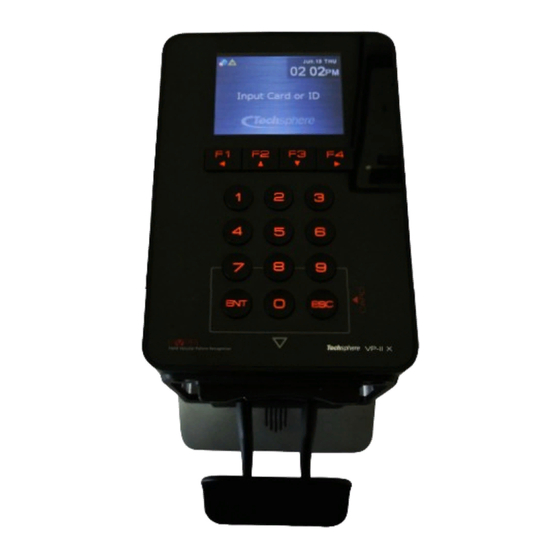
Chapter 1 Overview 1. VP-II X Scanner Display USB port Keypad RF Antenna Hand input indicator Trigger switch Speaker Handle Display Status indicator Date & Time... -
Page 7: Network Configuration
VP-II X or server. When there are more than 64 units of the VP-II X running in the same network, a VP-II X cannot be a master and the server must be run as a master. A VP-II X, when it is configured to a master, can only handle up to 63 slave units. -
Page 8: Networking Vp-Ii X
2.2 Networking VP-II X VP-II X units are networked through a TCP/IP network, and all databases of each unit are automatically synchronized. Although up to 64 units can be networked without a server computer, it is recommended that the application software (NetControl-X) running on a server be used in order to utilize the enhanced features of the VP-II X system such as detailed User management, anti-pass back, events, etc. -
Page 9: Vp-Ii X Specification
3. VP-II X Specification Environmental Specification Power Supply DC 12V / 1.5A (SMPS: AC 100~250V, 50Hz/60Hz) Operating Temperature -5 ~ 50°C Operating Humidity 10% ~ 90% Physical Specification Scanner: PC + ABS Material Rear plate & Bracket: Metal Weight 820g (Without card reader module) - Page 10 Hardware Specifications Core Processor Dual CPUs (400Mhz DSP, 180Mhz ARM Processor) 65K Color 2.8” TFT LCD with backlight Display Lifetime: 10 years Keypad 0~9, Enter, ESC, 4 Function keys RJ45 Ethernet TCP/IP (Between VP-II Xs and/or Server) Wiegand (Input: 1, Output: 1) External Interface Serial port: 2 channel I/O Ports...
-
Page 11: Guideline To Place A Hand
In order to maximize the performance in verifying the hand vascular pattern, it is strongly recommended that Users follow the instructions below in positioning as well as placing a hand in to the VP-II X Scanner. Stand properly in front of the Scanner, for example, if using right hand, position your feet to the left of the Scanner so that your arm is naturally straight towards to the Scanner. -
Page 12: Chapter 2 Enrollment, Deletion And Verification
It is required to access the Manager Menu in order to enrol/delete Users or change system setup. The Manager menu can only be accessed by a Manager or an Installer. The VP-II X is set to the Test Mode when delivered, which enables an Installer to be enrolled as a Manager. -
Page 13: Manager Menu Access
You can also directly enter a number key to select a menu if indexed with a number. 1.7 Menu Tree VP-II X Manager Menu 1. User Management 1. Enroll User 2. Delete User 3. - Page 14 4. UI Settings 1. Language Settings 2. Sound Settings 3. PIN Display Option 5. Card Settings 1. Wiegand Settings 2. Mifare Card 3. HID iClass Card 4. PACS Settings 6. Tools 1. Report 1. Network Diagnostics 2. Diagnostic Tools 2. Network Info. 3.
-
Page 15: Enrollment
2. Enrollment Users or Managers can be enrolled using the Manager Menu or through NetControl-X application software. Access to the Manager Menu is required to perform the following instructions to enrol Users and/or Managers. Please refer to the User’s guide of the NetControl-X for the details on how to enrol using the application software. -
Page 16: User/Manager Enrolment
System Level for the User to use the level set to the unit. It is recommended that you use the default which is System Level for the Users who are initially enrolled to the VP-II X. You can later assign a... - Page 17 Level 3 or higher. The Personal Security Level can be adjusted for individual Users based on their specific requirements. Each VP-II X unit has a security level (System Level), and it can be individually assigned to each User’s (Personal Security Level). When verifying a User, the VP-II X uses either Personal Security Level if assigned or System Level if the Personal Security Level is not assigned to the User.
-
Page 18: Deletion
For card Users, normally a card User is deleted by its Wiegand PIN when it is enabled; The VP-II X will delete a card User by using its card number. To match the card number exactly, VP-II X has to be set to the proper Wiegand format in the system. -
Page 19: Verification
4. Verification Verification is typically made by (1) entering a PIN or presenting a card, and (2) place a hand. When a PIN is entered or a card is presented, a sub-menu appears at the bottom of the screen as shown in the above figure. -
Page 20: Password User Verification
To verify a password User, (1) enter a PIN or present a card, (2) press F2 to proceed with a password input, and (3) Place a hand and push the trigger switch (VP-II X does not verify a hand but the User is required to trigger the switch). -
Page 21: Installer Verification
When the duress verification is made, the VP-II X can send an alarm event in three ways 1) it sends to NetControl-X software in real time and NetControl-X will generate an alarm message and/or send an e- mail to the pre-assigned accounts; 2) VP-II X also can output a digital signal through its AUX port by modifying its firmware upon request;... -
Page 22: Template Management (Add/Update Vascular Data)
User Class / Level User Class (Manager or User) and security level (Personal level from 1 to 5, or system level) can be re- assigned. Duress Select a hand (vascular data) to be used for duress verification. This function is available only when two hands are enrolled for one User. -
Page 23: Multiple Template Assignment
This eliminates the need to re-enter existing information such as User name (in the NetControl-X database), expiration time, etc, this information will all be maintained in the database. This function is not applicable for smart card Users. For a smart card User please see “Chapter 2 5.2.3 Smart Card Update”... -
Page 24: Chapter 3 Environment Setup
1. Network Setup It is required that a proper network environment is set in order to run the VP-II X in the TCP/IP network. An IP address (including subnet mask and gateway), master IP address, server IP address (if used), and slave information (only for master unit) must be set. -
Page 25: Server Setting
Master IP is not required if the Master Mode is selected. Please make sure that there is only one master unit in the same network. If the server (NetControl-X) is set to master, all VP-II X units must be set to be slaves. In this case you must enter the server IP address as the Master IP. -
Page 26: Slave List
VP-II X or server where the enrolled template is stored to verify their hand. Please refer to “Chapter 3 3.6” for instructions to set the verification location to “Only Network”. -
Page 27: System Setup
And then execute Search USB after plugging the USB device in the VP-II X USB port (Refer to “Chapter 1 1 VP-II X Scanner”). It will automatically search the firmware and perform upgrade if available. -
Page 28: Door Settings
VP-II X via RS232 (or RS485; an optional RS485 driver board needs to be installed at both VP-II X and XG to use RS485 interface). The VP-II XG has a relay output to connect an electrical lock and digital input ports for door status monitoring and exit button interface. -
Page 29: Daylight Saving Time
2.5 Daylight Saving Time If you are in daylight saving time zone, you can set VP-II X time to be adjusted by setting the start time and expire time of daylight saving time. Once set, the VP-II X’s time will be adjusted automatically based on the timeframe set. -
Page 30: System Initialization (Reset To Factory Settings)
2.6 System initialization (Reset to Factory Settings) You can reset all system settings back to factory settings. Note: Special caution is required when executing this function. Manager Menu > 3. System Settings > 7. Initialization Settings Init. Configuration This will initialize all settings back to factory set. Init. -
Page 31: Aux Settings
To allow for two Wiegand Input ports, the VP-II X AUX port can be configured to also accept Wiegand Input. This allows for a second Wiegand reader to be used as an exit reader. When VP-II X AUX port is set to Wiegand Input, the VP-II X will work in bypass mode and will check only the following user verification options: 1) User Expiration Date, 2) User Activation and 3) Gate Time zone. -
Page 32: Operation Settings
Manager Menu > 2. Operational Settings > 2. Test Mode If the Test Mode is released, the VP-II X does not show the Test Mode menu to enroll an Installer anymore. There are two options in releasing the Test Mode. -
Page 33: Sleep Mode
3.4 Sleep Mode VP-II X enters into a sleep mode when there is no User activity for the set period if enabled (factory default). It is not only to minimize power consumption but also to maximize the life time of the system. -
Page 34: Ui Settings
4. UI Settings 4.1 Language Settings VP-II X supports multiple languages. More languages will be added. Manager Menu > 4. UI Settings > 1. Language Settings 4.2 Sound Settings Manager Menu > 4. UI Settings > 1. Sound Settings Volume Set speaker volume from 0(silent) to 10(loudest). -
Page 35: Card Settings
VP-II X outputs a Wiegand code for interface with an external access control system when a User is successfully verified; (1) For card Users (proximity or smart card), the VP-II X outputs the Wiegand code as it is read from the card; and (2) For PIN Users, VP-II X outputs a Wiegand code created in accordance with the preset format. -
Page 36: Wiegand Output Options
The bit 13 is used for both odd and even parity calculation. 5.1.3 Wiegand Output Options VP-II X can also output a Wiegand code for verification failure and emergency notification (duress code). In order for PACS (Physical Access Control System) to recognize the difference for these codes, a separate site code needs to be assigned for each. -
Page 37: Mifare / Iclass Card
“Not installed”. Start Sector/Page Set the sectors (Mifare) or pages (HID) to be used for VP-II X template. Required space to store one User data is 7 sectors for Mifare and 2 pages for HID. Blank Card Type (Mifare) - Page 38 The VP-II X uses a key to encrypt the data stored in a smart card. For security reasons, customers should assign a unique key to be utilized for their VP-II X devices. The key is stored in both VP-II X and the card, and the key in the card must be matched to that in the VP-II X to be accepted.
-
Page 39: Pacs System Settings
A detection level signal will be sent from PACS system to VP-II X. The detection ime is the expected time when the PACS system will respond to the VP-II X. VP-II X can be configured to detect a signal of 0V or 5V. -
Page 40: Tools
Internet Protocol network. When a manager selects the “Test” menu, the VP-II X will send test packets to the device that’s IP address is specified. After about 10 seconds, the VP-II X will display the result. By using this tool, a manager can determine whether there is problem with their network configuration. -
Page 41: Soft Reset
6.3 Soft Reset This allows the manager to reboot the VP-II X when required without the need to unplug power cord in the back. Manager Menu > 6. Tools > 3. Soft Reset Socket Restart The VP-II X will reset and restart all related network protocols with the scanner. -
Page 42: Chapter 4 Appendix
XConfig. When you click the Search (F5) button, it will show all VP-II Xs available on the network. Select a VP-II X or multiple VP-II X units to download the firmware. In the following example, two VP-II Xs are selected. - Page 43 The power of VP-II X must be kept on in order to write complete firmware to its memory. Removing power while upgrading firmware may hang up the system due to incomplete firmware installation.
-
Page 44: Quick Installation Guide
(4Φ×30mm) Fix VP-II X on the Bracket Put the VP-II X on the bracket and push all the way down. And then fix the VP-II X on the bracket using the bracket screw located in the sensor module hosing. Bracket screw... -
Page 45: Ports And Connections
DC JACK / EXT PWR DC JACK is used to plug in a power supply provided along the VP-II X. The input range of the power supply included in the package is AC100~250 / 50~60Hz, and output is DC 12V / 1.5A. If you need to supply the power to an external device connected to the VP-II X, such as an external card reader, you can use EXT PWR port. - Page 46 Serial port B is reserved for future uses. RS-485 In case that the distance between VP-II X and VP-II XG is over 15 meters, the RS485 interface can be used. However, an RS485 driver which is not installed by default has to be additionally installed inside both the VP-II X and VP-II XG.
-
Page 47: Event Report Viewer
3. Event Report Viewer An application (“VP Report”) is provided by Techsphere for implementations where the VP-II X unit(s) are not using a server. In this case, the Manager can export stored events to a USB memory device to see and diagnose user management events. -
Page 48: Tray Icons
4. Tray Icons VP-II X displays the current status of VP-II X with icons. The icons allow a Manager to quickly see the current status of the VP-II X, see the icons and their descriptions in the table below: Icon...
Need help?
Do you have a question about the VP-II X and is the answer not in the manual?
Questions and answers