Table of Contents
Advertisement
Quick Links
Advertisement
Table of Contents

Related Manuals for Samson 3510-1


Summary of Contents for Samson 3510-1
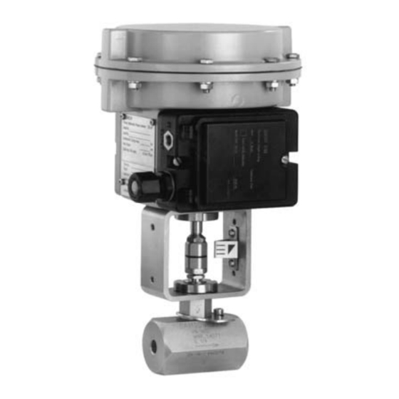
- Page 1 Pneumatic Control Valve Type 3510-1 and Type 3510-7 Type 3510-1 with 120 cm actuator Type 3510-7 with 120 cm actuator and integrated positioner Type 3510-1 with 60 cm actuator Fig. 1 ⋅ Pneumatic control valves Mounting and Operating Instructions EB 8091 EN...
-
Page 2: Table Of Contents
Contents Contents Page Design and principle of operation ..... . 4 Assembling and adjusting valve and actuator ....6 Signal pressure connection . - Page 3 Safety instructions The device may only be assembled, started up or operated by trained and ex- perienced personnel familiar with the product. According to these mounting and operating instructions, trained personnel is referred to as individuals who are able to judge the work they are assigned to and recognize possible dangers due to their specialized training, their knowl- edge and experience, as well as their knowledge of the applicable standards.
-
Page 4: Design And Principle Of Operation
The angle body style) and either a Type 3271-5 plug stem (6) is connected to the actuator Pneumatic Actuator (Type 3510-1 Control stem (8.1) via the stem connector (7) and Valve) or a Type 3277-5 Pneumatic Actua- sealed with an adjustable stuffing box with tor (Type 3510-7 Control Valve). - Page 5 Design and principle of operation Actuator stem extends: Actuator stem retracts: When the signal pressure is reduced or in When the signal pressure is reduced or in case of a supply air failure, the springs case of a supply air failure, the springs move the actuator stem downwards and move the actuator stem upwards and open close the valve.
-
Page 6: Assembling And Adjusting Valve And Actuator
Turn the connecting plate, so that the ap- 2.1 Signal pressure connection propriate symbol for the fail-safe action "Actuator stem extends" or "Actuator Type 3510-1 Control Valve stem retracts" is aligned to the mark. with Type 3271-5 Actuator Make absolutely sure that the gasket of The signal pressure connection for fail- the connecting plate is inserted correctly. -
Page 7: Assembly And Adjustment
Assembling and adjusting valve and actuator Note! 2.2 Assembly and adjustment When used in connection with the micro- flow valve, the pneumatic actuators with fail- For actuators with a switchover plate for at- safe action "Actuator stem retracts" are tachment of a positioner, a suitable adapter limited to the max. -
Page 8: Installation
Installation ing the actuator stem to retract far 3 Installation enough to screw together stem connec- tor nut (7.1) and stem connector sleeve 3.1 Mounting position (7.2). Any desired mounting position is possible. 4. Screw together stem connector sleeve (7.2) and stem connector nut (7.1) as Note! Make sure the valve is installed free tightly as possible. -
Page 9: Troubleshooting
Troubleshooting 5 Troubleshooting If the valve leaks, the packing may be defec- tive or, in the bellows version, the metal bel- lows may be defective. Tight shut-off of the valve can also be im- paired by impurities or other foreign par- ticles between seat and plug, or by dam- aged seat joints. -
Page 10: Replacing The Stuffing Box Packing
Troubleshooting sure not to damage the sealing edges. 5.1 Replacing the stuffing box Clean packing chamber thoroughly. packing Assembly: If leakage occurs at the stuffing box, the stuffing box packing must be replaced as 7. Insert new sealing rings. Start with a described below. - Page 11 Troubleshooting enough to screw together stem connec- 15. Check adjustment according to instruc- tor nut (7.1) and stem connector sleeve tions given in section 2.2, items 5 to 8. (7.2). 14. Screw together stem connector sleeve (7.2) and stem connector nut (7.1) as tightly as possible.
-
Page 12: Replacing Seat And Plug
Troubleshooting Versions with bellows seal or insulating 5.2 Replacing seat and plug section: Standard version: Unscrew valve bonnet (5). For assembly/disassembly, proceed as In the insulating section version, remove described in section 5.1. Additionally, insulating section (9) from the valve unscrew the seat (2.1) using a socket body, so that the plug stem including wrench. - Page 13 Screw Plug Anti-rotation device with trim identification number Valve bonnet Bellows intermediate piece/insulating section Sealing ring Sealing ring Bellows seal 10.1 10.1 Plug stem extension (in version with insulating section without metal bellows) Anti-rotation device Anti-rotation device Screw Disk Test connection (optional) Fig.
-
Page 14: Customer Inquiries
Customer inquiries 6 Customer inquiries Please include the following details in your inquiry: Order number Type, product and identification number Valve style: globe or angle valve Nominal size and pressure of the valve, additionally K value and the identifica- tion number of the attached trim Pressure, density, viscosity and tempera- ture of the flow medium Flow rate in m... - Page 15 EB 8091 EN...
- Page 16 SAMSON AG ⋅ MESS- UND REGELTECHNIK Weismüllerstraße 3 ⋅ 60314 Frankfurt am Main ⋅ Germany Phone: +49 69 4009-0 ⋅ Fax: +49 69 4009-1507 EB 8091 EN Internet: http://www.samson.de...
Need help?
Do you have a question about the 3510-1 and is the answer not in the manual?
Questions and answers