Table of Contents
Advertisement
Quick Links
Advertisement
Chapters
Table of Contents

Subscribe to Our Youtube Channel
Related Manuals for Samson 3510


Summary of Contents for Samson 3510
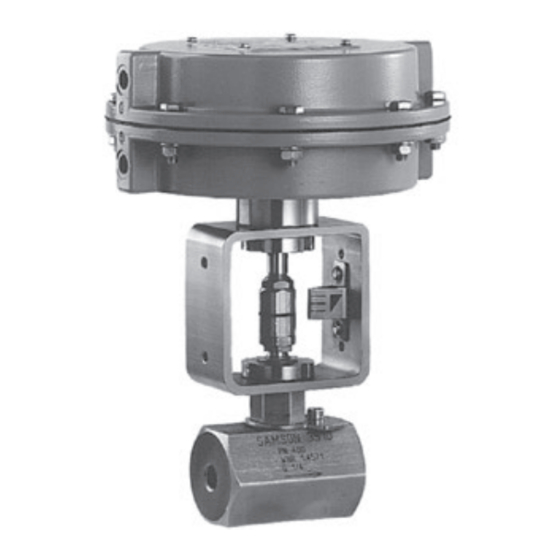
- Page 1 Type 3510 Micro-flow Valve In combination with an actuator, e.g. a SAMSON Type 3271 or Type 3277 Pneumatic Actuator ANSI version Type 3510-1 (left) and Type 3510-7 (right) Pneumatic Control Valves Mounting and Operating Instructions EB 8091-1 EN Edition September 2016...
- Page 2 Î For the safe and proper use of these instructions, read them carefully and keep them for later reference. Î If you have any questions about these instructions, contact SAMSON‘s After-sales Service Department (aftersalesservice@samson.de). The mounting and operating instructions for the devices are included in the scope of delivery.
-
Page 3: Table Of Contents
Contents Safety instructions and measures ..............5 Notes on possible severe personal injury ............7 Notes on possible personal injury ..............8 Notes on possible property damage ..............9 Markings on the control valve ..............10 Body inscription ...................10 Actuator nameplate ..................11 Material number ..................11 Design and principle of operation ..............12 Fail-safe positions ..................12 Versions ......................14... - Page 4 Contents 7.1.3 Version with bellows seal ................34 Replacing the packing ..................36 Replacing the seat and plug ................38 7.3.1 Standard version..................38 7.3.2 Version with insulating section ...............39 Preparation for return shipment ..............40 Ordering spare parts and operating supplies ..........41 Malfunctions ....................42 Troubleshooting ...................42 Emergency action ..................43 Decommissioning and disassembly ..............44...
-
Page 5: Safety Instructions And Measures
SAMSON must be contacted. SAMSON does not assume any liability for damage resulting from the failure to use the valve for its intended purpose or for damage caused by external forces or any other external factors. - Page 6 Î Check with the plant operator for details on further protective equipment. Revisions and other modifications Revisions, conversions or other modifications to the product are not authorized by SAMSON. They are performed at the user's own risk and may lead to safety hazards, for example. Fur- thermore, the product may no longer meet the requirements for its intended use.
-
Page 7: Notes On Possible Severe Personal Injury
Safety instructions and measures Referenced standards and regulations The control valves comply with the requirements of the European Pressure Equipment Direc- tive 2014/68/EU. According to the ignition risk assessment performed in accordance with EN 13463-1:2009, section 5.2, the non-electrical control valves do not have their own potential ignition source even in the rare incident of an operating fault. -
Page 8: Notes On Possible Personal Injury
Risk of personal injury due to preloaded springs. Valves in combination with pneumatic actuators with preloaded springs are under ten- sion. These control valves with SAMSON pneumatic actuators can be identified by the long bolts protruding from the bottom of the actuator. -
Page 9: Notes On Possible Property Damage
Safety instructions and measures WARNING Risk of burn injuries due to hot or cold components and pipelines. Depending on the process medium, valve components, and pipelines may get very hot or cold and cause burn injuries. Î Allow components and pipelines to cool down or heat up. Î... -
Page 10: Markings On The Control Valve
Risk of valve damage due to the use of unsuitable tools. Certain tools are required to work on the valve. Î Only use tools approved by SAMSON (u AB 0100). Risk of valve damage due to the use of unsuitable lubricants. The lubricants to be used depend on the valve material. Unsuitable lubricants may cor- rode and damage the valve surface. -
Page 11: Actuator Nameplate
2.2 Actuator nameplate Only install matching trim parts. See associated actuator documentation. 2.3 Material number The valve are marked as follows: Seat − Material number − SAMSON consecutive number Plug 1.4404 Plug Seat 1.4404 0,025 lin − Material number 4 711 −... -
Page 12: Design And Principle Of Operation
As a result, the plug position in the seat changes and determines ation the flow rate through the valve. The Type 3510 Micro-flow Valve is available 3.1 Fail-safe positions as either a globe or angle valve and is pref- erably combined with a SAMSON The fail-safe position depends on the actua- Type 3271 or Type 3277 Pneumatic Actuator... - Page 13 Travel indicator scale Hexagon nut Packing Actuator stem Ring nut A27.1 Stem connector nut A27.2 Bearing sleeve (bottom part of the stem connector) A27.3 Lock nut Fig. 3: Type 3510 Micro-flow Valve as globe valve with Type 3271 Pneumatic Actuator EB 8091-1 EN...
-
Page 14: Versions
This provides more space to mount valve accesso- Compliance ries. The Type 3510 Valve bears the EAC mark of conformity: Actuators In these instructions, the preferable combina- tion with a Type 3271 or Type 3277 Pneu- matic Actuator is described. - Page 15 Design and principle of operation Noise emission SAMSON is unable to make general state- ments about noise emission as it depends on the valve version, plant facilities, and process medium. On request, SAMSON can perform calculations according to IEC 60534, Part 8-3 and Part 8-4 or VDMA 24422 (edi- tion 89).
- Page 16 The lengths and heights in the dimensional drawings are shown on p. 18. Note Dimensions and weights for Type 3271 and Type 3277 Pneumatic Actuators with 120 cm² actuator area can found in the Data Sheet u T 8310-1. Table 1: Dimensions for Type 3510 Valve Female Welding ends Flanges...
- Page 17 Design and principle of operation Female Welding ends Flanges thread Connection G/NPT/ NPS ½ NPS 1 NPS ½ NPS ¾ NPS 1 to ¾ 4.80 120 cm² Insulating section 10.35”/263 mm up to Class 2500 Bellows seal up to 10.35”/263 mm Class 600 Bellows seal up to 14.37”/365 mm Class 1500 3.54 3.94...
- Page 18 Design and principle of operation Dimensional drawings SW50 Type 3510 as angle valve with Type 3510 as globe valve with female thread female thread, with bellows seal or insulat- ing section EB 8091-1 EN...
- Page 19 Design and principle of operation Type 3510 · Valve body with flanges and welding ends Table 2: Weights for Type 3510 Valve Female Welding Flanges thread ends Connection G/NPT/Rc NPS ½, NPS ½ NPS ¾ NPS 1 to ¾ NPS 1 3.74 Class 150 3.74 10.6 Class 300 Valve 3.74...
-
Page 20: Measures For Preparation
+149 °F (–20 to +65 °C). Proceed as follows to lift and install the Information valve: Contact SAMSON's After-sales Service de- 1. Remove the packaging from the valve. partment for the transportation temperatures 2. Dispose of the packaging in accordance of other valve versions. -
Page 21: Storage
− Observe storage instructions. − Do not place any objects on the control − Avoid long storage times. valve. − Contact SAMSON in case of different stor- Special storage instructions for elastomers age conditions or long storage periods. Elastomer, e.g. actuator diaphragm −... - Page 22 Measures for preparation Î Check to make sure that the type desig- nation, valve size, material, pressure rat- ing and temperature range of the valve match the plant conditions (size and pressure rating of the pipeline, medium temperature etc.). Î For steam applications, make sure that the pipelines are dry.
-
Page 23: Mounting And Start-Up
Mounting and start-up 5 Mounting and start-up Note SAMSON valves are delivered ready for − Remove the mounted actuator before use. In special cases, the valve and actuator mounting the other actuator (see associat- are delivered separately and must be assem- ed actuator documentation). - Page 24 Mounting and start-up Table 3: Inlet and outlet lengths Flow rate Inlet length Outlet length a x DN b x DN State of process Inlet Outlet Valve conditions medium length a length b Ma ≤ 0.3 0.3 ≤ Ma ≤ 0.7 Ma ≤ 0.3 1) Vapor 0.3 ≤ Ma ≤ 0.7 1) Saturated steam (percentage of condensate > 5 %) Free of cavitation/w < 10 m/s Cavitation producing noise/w ≤ 3 m/s Liquid...
-
Page 25: Additional Fittings
The mounting kit (item no. 1400-9031) can be ordered from Insulation SAMSON. Refer to the mounting and oper- Only insulate control valves with insulating ating instructions of the corresponding de- section or bellows seal up to the bonnet vice for a description on how to mount it. -
Page 26: Quick Check
5.3 Quick check 3. Lift the valve to the site of installation. Observe the flow direction through the SAMSON valves are delivered ready for valve. The arrow on the valve indicates use. To test the valve's ability to function, the the direction of flow. - Page 27 − Observe the maximum permissible pres- sure for valve and plant. Note The plant operator is responsible for per- forming the pressure test. SAMSON's Af- ter-sales Service department can support you to plan and perform a pressure test for your plant.
-
Page 28: Operation
Operation 6 Operation 6.1 Working in manual mode Immediately after completing mounting and Valves fitted with actuators with a handwheel start-up (see section 5), the valve is ready for can be manually closed or opened in case of use. supply air failure. Î... - Page 29 EB 8091-1 EN...
-
Page 30: Servicing
− Wear protective clothing, safety gloves, and eyewear. SAMSON's After-sales Service department WARNING can support you to draw up an inspection plan for your plant. Risk of burn injuries due to hot or cold com- ponents and pipeline. -
Page 31: Replacing The Gasket
(1) and on the intermediate piece (4). Note 6. Insert a new gasket (2.3) into the body. The control valve was checked by SAMSON 7. Apply a suitable lubricant to the thread before it left the factory. of the intermediate piece. - Page 32 Travel indicator scale Hexagon nut Packing Actuator stem Ring nut A27.1 Stem connector nut A27.2 Bearing sleeve (bottom part of the stem connector) A27.3 Lock nut Fig. 4: Type 3510 Micro-flow Valve as globe valve with Type 3271 Pneumatic Actuator EB 8091-1 EN...
-
Page 33: Intermediate Piece
(7). Legend for Fig. 5 Intermediate piece 24.1 Seal Insulating section Plug stem extension Fillister head screw 24.1 Bottom anti-rotation fixture 24.2 Top anti-rotation fixture (two-piece) Washer Hexagon nut Fig. 5: Type 3510 with insulating section Washer EB 8091-1 EN... -
Page 34: Version With Bellows Seal
Servicing 10. Unscrew the insulating section (7) from tool to screw it in. Observe tightening the body (1). Remove the insulating sec- torques. tion (7) together with the plug (2.1) and plug stem extension (22) from the body Note (1). It must be possible to turn the washer (27) 11. - Page 35 Plug stem with bellows Seal (on intermediate piece) Bottom anti-rotation fixture Intermediate piece Bellows seal Fillister head screw 24.2 Top anti-rotation fixture (two-piece) Washer Hexagon nut Fig. 6: Type 3510 with bellows seal and test Washer connection Test connection EB 8091-1 EN...
-
Page 36: Replacing The Packing
Servicing 12. Remove gasket (2.3). Carefully clean the 21. Apply a suitable lubricant to the thread sealing faces in the valve body (1) and of the intermediate piece (4). on the bellows seal (7). 22. Carefully place the intermediate piece (4) 13. -
Page 37: Threaded Bushing
Servicing To replace the packing in other valve ver- 8. Carefully slide the packing parts over the sions, contact SAMSON's After-sales Service plug stem into the packing chamber us- department. ing a suitable tool. Observe the proper sequence (see Fig. 7). -
Page 38: Replacing The Seat And Plug
− The valve does not have a bellows seal. anti-rotation fixture (2.4) from the inter- To replace seat and plug in other valve ver- mediate piece (4). sions, contact SAMSON's After-sales Service 4. Unscrew the intermediate piece (4) from department. the body (1). Remove the intermediate piece (4) together with plug (2.1) from... -
Page 39: Version With Insulating Section
Servicing 15. Place the intermediate piece (4) together 6. Remove the washer (27) from the insulat- with the plug (2.1) onto the body. Use a ing section (7). suitable tool to screw it into the body (1). 7. Remove the bottom section of the top an- Observe tightening torques. -
Page 40: Preparation For Return Shipment
It must be possible to turn the washer (27) 4. Send the valve together with the filled-in easily after the intermediate piece is fastened form to your nearest SAMSON subsidi- tight. It must not be clamped down. ary. SAMSON subsidiaries are listed on our website at u www.samson.de >... -
Page 41: Ordering Spare Parts And Operating Supplies
Servicing 7.5 Ordering spare parts and operating supplies Contact your nearest SAMSON subsidiary or the SAMSON After-sales Service depart- ment for information on spare parts, lubri- cants, and tools. Spare parts See section 10.2 for details on spare parts. Lubricant Details on suitable lubricants can be found in the document u AB 0100. -
Page 42: Malfunctions
Depending on the operating conditions, check the valve at certain intervals to prevent possi- ble failure before it can occur. Operators are responsible for drawing up an inspection plan. SAMSON's After-sales Service department can support you to draw up an inspection plan for your plant. -
Page 43: Emergency Action
Malfunctions Note Contact SAMSON's After-sales Service department for malfunctions not listed in the table. 8.2 Emergency action Putting the valve back into operation after a malfunction Upon supply air or control signal failure, the Î Slowly open the shut-off valves. Allow... -
Page 44: Decommissioning And Disassembly
Decommissioning and disassembly 9 Decommissioning and disas- WARNING sembly Risk of burn injuries due to hot or cold com- ponents and pipeline. Valve components and the pipeline may be- DANGER come very hot or cold. Risk of burn injuries. Risk of bursting in pressure equipment. −... -
Page 45: Removing The Actuator From The Valve
Addresses of SAMSON AG and its subsid- 9.3 Removing the actuator iaries from the valve The addresses of SAMSON AG, its subsid- iaries, representatives, and service facilities See associated actuator documentation. worldwide can be found on the SAMSON website, in all SAMSON product catalogs or 9.4 Disposal... -
Page 46: Spare Parts
Appendix 10.2 Spare parts Body Hexagon nut Trim Washer Plug with plug stem Seal for test connection Seat Screw plug Body gasket Yoke (ready mounted) Anti-rotation fixture Packing Bellows (assembly) Lower part of the stem connector (assembly) Plug stem with bellows Seal Bellows nut Note... - Page 47 Appendix 24.2 24.2 24.2 24.1 EB 8091-1 EN...
-
Page 48: Eb 8091-1 En
SAMSON AG · MESS- UND REGELTECHNIK Weismüllerstraße 3 · 60314 Frankfurt am Main, Germany Phone: +49 69 4009-0 · Fax: +49 69 4009-1507 EB 8091-1 EN samson@samson.de · www.samson.de...
Need help?
Do you have a question about the 3510 and is the answer not in the manual?
Questions and answers