
Subscribe to Our Youtube Channel
Related Manuals for Samson 3522


Summary of Contents for Samson 3522
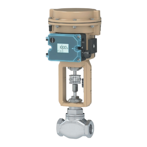
- Page 1 EB 8822 EN Translation of original instructions Type 3522 Globe Valve · ANSI version In combination with an actuator, e.g. a Type 3271 or Type 3277 Pneumatic Actuator Edition September 2021...
- Page 2 Note on these mounting and operating instructions These mounting and operating instructions assist you in mounting and operating the device safely. The instructions are binding for handling SAMSON devices. The images shown in these instructions are for illustration purposes only. The actual product may vary.
-
Page 3: Table Of Contents
Contents Safety instructions and measures ..............5 Notes on possible severe personal injury ............8 Notes on possible personal injury ..............8 Notes on possible property damage ..............10 Markings on the control valve ..............12 Valve nameplate ..................12 Actuator nameplate ..................13 Material identification number ..............13 Design and principle of operation ..............14 Fail-safe positions ..................16 Additional fittings ..................16... - Page 4 Removal .....................46 11.1 Removing the valve from the pipeline .............47 11.2 Removing the actuator from the valve ............47 Repairs .......................48 12.1 Returning devices to SAMSON ..............48 Disposal ......................48 Certificates ....................49 Annex......................50 15.1 Tools, tightening torques and lubricants ............50 15.2 Spare parts ....................52 15.3...
-
Page 5: Safety Instructions And Measures
In case operators intend to use the control valve in other applica- tions or conditions than specified, contact SAMSON. SAMSON does not assume any liability for damage resulting from the failure to use the de- vice for its intended purpose or for damage caused by external forces or any other external factors. - Page 6 Î Check with the plant operator for details on further protective equipment. Revisions and other modifications Revisions, conversions or other modifications of the product are not authorized by SAMSON. They are performed at the user's own risk and may lead to safety hazards, for example. Fur- thermore, the product may no longer meet the requirements for its intended use.
- Page 7 Start-up and shutdown procedures fall within the scope of the operator's duties and, as such, are not part of these mounting and operating instructions. SAMSON is unable to make any statements about these procedures since the operative details (e.g. differential pressures and temperatures) vary in each individual case and are only known to the operator.
-
Page 8: Notes On Possible Severe Personal Injury
Safety instructions and measures 1.1 Notes on possible severe personal injury DANGER Risk of bursting in pressure equipment. Valves and pipelines are pressure equipment. Impermissible pressure or improper open- ing can lead to valve components bursting. Î Observe the maximum permissible pressure for valve and plant. Î... - Page 9 Risk of personal injury due to preloaded springs. Valves in combination with pneumatic actuators with preloaded springs are under ten- sion. These control valves with SAMSON pneumatic actuators can be identified by the long bolts protruding from the bottom of the actuator.
-
Page 10: Notes On Possible Property Damage
Safety instructions and measures WARNING Exposure to hazardous substances poses a serious risk to health. Certain lubricants and cleaning agents are classified as hazardous substances. These substances have a special label and a material safety data sheet (MSDS) issued by the manufacturer. - Page 11 Risk of valve damage due to the use of unsuitable lubricants. The lubricants to be used depend on the valve material. Unsuitable lubricants may cor- rode and damage surfaces. Î Only use lubricants approved by SAMSON (see bill of materials and section 15.1). EB 8822 EN...
-
Page 12: Markings On The Control Valve
ST: base material with Stellite facing or solid Stellite ® ® PT: soft seal with PTFE Option code for trim identification (stem, plug, seat) – Fig. 1: Type 3522 nameplate The nameplate is affixed to the back of the valve body. EB 8822 EN... -
Page 13: Actuator Nameplate
(see Ta- ble 1). This seat code is specified on the nameplate (seat/plug seal, 15). For more details on the nameplate, see section 2.1. Table 1: Seat codes Valve Type 3522 Plug stem material A479 316/A479 316L A182 F316/ Plug material A479 316/A479 316L R30006 (Stellite ®... -
Page 14: Design And Principle Of Operation
In these instructions, the combination with a Type 3271 or Type 3277 Pneumatic Actuator The Type 3522 Valve is a single-seated is described. The pneumatic actuator can be globe valve. This valve is preferably com- replaced by another pneumatic actuator in a bined with a SAMSON Type 3271 or... - Page 15 Design and principle of operation Fig. 2: Type 3522 Globe Valve with Body threaded ends and Type 3271 Bonnet Pneumatic Actuator Seat Plug Threaded bushing (packing nut) Stem connector nut Lock nut Packing Body gasket Yoke assembly A26/27 Travel indicator scale Actuator stem A26/27 Stem connector clamp Fig. 3:...
-
Page 16: Fail-Safe Positions
Depending on how the compression springs damaging the valve. are arranged in the SAMSON Type 3271 Bypass and shut-off valves and Type 3277 Pneumatic Actuator, the valve has one of two different fail-safe posi-... -
Page 17: Technical Data
Dimensions and weights Table 2 to Table 4 provide an overview of the dimensions and weights of the threaded and flanged version of Type 3522 Valve. The lengths and heights are shown in the dimen- sional drawings on page p. 18 and p. 19. - Page 18 Design and principle of operation Table 2: Dimensions of Type 3522 Valve · Version with threaded ends Valve ½ ¾ 1¼ 1½ 4.31 4.63 5.31 6.66 Length L Class 300 Type 3271, 8.66 8.75 8.98 Type 3277 ≤350 cm² H1 for actuator 10.6 Type 3372 – 1.13 1.13...
- Page 19 Design and principle of operation Table 3: Dimensions of Type 3522 Valve · Version with flanges Pressure Valve ½ ¾ 1¼ 1½ rating Class 150 – Length L 10.5 Class 300 – Type 3271, 8.66 – 8.98 Type 3277 H1 for ≤350 cm² – actuator 10.6 Type 3372 –...
- Page 20 Design and principle of operation Table 4: Weights of Type 3522 Valve without actuator Valve ½ ¾ 1¼ 1½ Version with threaded ends 11.5 14.8 16.8 – 31.1 34.6 Version with flanges – 14.1 15.7 Note Refer to the following data sheets for more dimensions and weights: u T 8310-1 for Type 3271 or Type 3277 Pneumatic Actuators up to 750 cm²...
-
Page 21: Shipment And On-Site Transport
2. Check the shipment for transportation Î Stay clear of suspended or moving damage. Report any damage to loads. SAMSON and the forwarding agent (re- Î Close off and secure the transport paths. fer to delivery note). 3. Determine the weight and dimensions of... -
Page 22: Transporting The Valve
Risk of personal injury due to the control A swivel hoist can be screwed into valve tipping over. SAMSON actuators with a female thread on Î Observe the valve's center of gravity. the top diaphragm case in place of the eye- Î... - Page 23 Shipment and on-site transport − Protect the piping and any mounted Note valve accessories against damage. Contact our after-sales service for the trans- − Protect the control valve against moisture portation temperatures of other valve ver- and dirt. sions. − The permissible transportation tempera- ture of standard control valves is –4 to +149 °F (–20 to +65 °C).
-
Page 24: Lifting The Valve
Shipment and on-site transport 4.3.2 Lifting the valve 2. Carefully lift the control valve. Check whether the lifting equipment and acces- To install a large valve into the pipeline, use sories can bear the weight. lifting equipment (e.g. crane or forklift) to lift 3. -
Page 25: Storing The Valve
Elastomer, e.g. actuator diaphragm Î Avoid long storage times. − To keep elastomers in shape and to pre- Î Contact SAMSON in case of different vent cracking, do not bend them or hang storage conditions or longer storage them up. - Page 26 Î Observe the recommended inlet and out- let lengths (see Table 5). Contact Pipeline routing SAMSON if the valve conditions or states The inlet and outlet lengths (see Table 5) vary of the medium process deviate. depending on several variables and process Î...
-
Page 27: Preparation For Installation
5.2 Preparation for installation the valve. Before installation, make sure the following Î Contact SAMSON if the mounting posi- conditions are met: tion is not as specified above. − The valve is clean. -
Page 28: Mounting The Device
Î Lay out the necessary material and tools Risk of valve damage due to the use of un- to have them ready during installation suitable tools. work. Î Only use tools approved by SAMSON Î Flush the pipelines. (see section 15.1). Note 5.3.1... -
Page 29: Installing The Valve Into The Pipeline
Installation 5.3.2 Installing the valve into Î Before mounting the actuator, determine which V-shaped port is uncovered first the pipeline when the plug is lifted out of the seat. Î On mounting the actuator, make sure NOTICE that the V-shaped port uncovered first Premature wear and leakage due to insuffi- faces toward the valve outlet. -
Page 30: Testing The Installed Valve
Installation 5.4 Testing the installed valve WARNING WARNING Crush hazard arising from actuator and DANGER plug stem moving. Risk of bursting due to incorrect opening of Î Do not insert hands or finger into the pressurized equipment or components. yoke while the air supply is connected to Valves and pipelines are pressure equipment the actuator. -
Page 31: Leak Test
Installation 5. Check the valve for leakage to the atmo- WARNING sphere. Risk of personal injury due to preloaded 6. Depressurize the pipeline section and springs. valve. Actuators with preloaded springs are under 7. Rework any parts that leak and repeat tension. -
Page 32: Start-Up
Start-up During the pressure test, make sure the fol- WARNING WARNING lowing conditions are met: Crush hazard arising from actuator and − Retract the plug stem to open the valve. plug stem moving. − Observe the maximum permissible pres- Î Do not insert hands or finger into the sure for both the valve and plant. -
Page 33: Start-Up/Putting The Device Back Into Operation
Operation − The leak and function tests have been NOTICE completed successfully (see section 5.4). Risk of valve damage due to altered forces. − The prevailing conditions in the plant When reversing the flow direction, altered section concerned meet the valve sizing forces occur which may damage the valve if requirements (see information under “In- incorrectly calculated. -
Page 34: Normal Operation
Operation 7.1 Normal operation pneumatic actuator or pneumatic valve ac- cessories not fitted with noise-reducing fit- The handwheel of valves with actuators fitted tings. Both can damage hearing. with a handwheel must be in the neutral po- Î Wear hearing protection when working sition during normal operation. -
Page 35: Malfunctions
Malfunctions 8 Malfunctions Read hazard statements, warnings and caution notes in sections 1.1, 1.2 and 1.3. 8.1 Troubleshooting Malfunction Possible reasons Recommended action Actuator and plug stem Actuator is blocked. Check attachment. does not move on de- Remove the blockage. WARNING! A blocked actuator or plug stem (e.g. mand. -
Page 36: Emergency Action
Malfunctions Malfunction Possible reasons Recommended action The valve leaks to the Defective packing Replace packing (see section 9) or contact our af- atmosphere (fugitive ter-sales service. emissions). Thread joint loose or Check the screw joint. Re-tighten, if necessary. seal worn. Check the seal at the threaded joint. Exchange, if necessary. -
Page 37: Servicing
Servicing 9 Servicing Î Wear protective clothing and safety gloves. The work described in this section is only to be performed by personnel appropriately qualified to carry out such tasks. WARNING The following documents are also required Risk of hearing loss or deafness due to loud for servicing the valve: noise. - Page 38 Risk of valve damage due to the use of Actuators with preloaded springs are under unsuitable tools. tension. They can be identified by the long Î Only use tools approved by SAMSON bolts protruding from the bottom of the actu- (see section 15.1). ator.
-
Page 39: Periodic Testing
Servicing − Only use original spare parts by SAMSON, which comply with the original Our after-sales service can support you in specifications. drawing up an inspection and test plan for your plant. 9.1 Periodic testing Depending on the operating conditions, check the valve at certain intervals to prevent possible failure before it can occur. -
Page 40: Preparing The Valve For Service Work
Servicing Inspection and testing Action to be taken in the event of a negative result: Check to ensure that the actuator and Unblock a blocked actuator and plug stem. plug stem move smoothly. WARNING! A blocked actuator or plug stem (e.g. due to seizing up after remaining in the same position for a long time) can suddenly start to move uncontrollably. - Page 41 Servicing Fig. 6: Type 3522 Globe Valve with threaded ends and Type 3271 Pneumatic Actuator A26/27 Fig. 7: Type 3522 Globe Valve with flanges Body Packing (complete) Bonnet Body gasket Seat Yoke assembly Plug Travel indicator scale Threaded bushing (packing nut) Stem connector nut Actuator stem...
-
Page 42: Service Work
Servicing 9.4 Service work 5. Apply a suitable lubricant to the bonnet (2). Î Before performing any service work, 6. Place bonnet (2) together with plug and preparations must be made to the control plug stem (5) onto the body (1). valve (see section 9.2). - Page 43 Servicing 6. Renew damaged parts. Clean the pack- 9. Version with V-port plug: place the ing chamber thoroughly. flange (2) onto the valve body, making sure that the largest V-shaped port of the 7. Apply a suitable lubricant to all the pack- V-port plug faces towards the valve out- ing parts and to the plug stem (5).
-
Page 44: Replacing The Seat And Plug
Servicing 9.4.3 Replacing the seat and 7. Pull the plug with plug stem (5) out of the bonnet (2). plug 8. Replace the packing (15) (see sec- tion 9.4.2) NOTICE 9. Unscrew the seat (4) using a suitable Risk of damage to the facing of the seat tool. -
Page 45: Ordering Spare Parts And Operating Supplies
Contact your nearest SAMSON subsidiary or SAMSON's After-sales Service for infor- mation on spare parts, lubricants and tools. WARNING Spare parts Risk of burn injuries due to hot or cold com- ponents and pipeline. -
Page 46: Removal
Removal ing on its properties, cause personal injury, WARNING WARNING e.g. (chemical) burns. Crush hazard arising from actuator and Î Wear protective clothing, safety gloves, plug stem moving. respiratory protection and eye protec- Î Do not insert hands or finger into the tion. -
Page 47: Removing The Valve From The Pipeline
Removal Î Allow components and pipelines to cool WARNING down or warm up to the ambient tem- Risk of personal injury due to preloaded perature. springs. Î Wear protective clothing and safety Actuators with preloaded springs are under gloves. tension. They can be identified by the long bolts protruding from the bottom of the actu- ator. -
Page 48: Repairs
Î Do not perform any repair work on your of your shipment so that the documents own. are clearly visible. Î Contact SAMSON's After-sales Service 4. Send the shipment to the address given for repair work. on the RMA. 12.1 Returning devices to... -
Page 49: Certificates
Certificates 14 Certificates Certificates are available on request. If in doubt, contact our after-sales service. EB 8822 EN... -
Page 50: Annex
Annex 15 Annex 15.1 Tools, tightening torques and lubricants See Table 6, Table 7, Table 8, and Table 9. WARNING Damage to health after contact with haz- ardous substances. Certain lubricants (e.g. 8150-4008) are classified as hazardous substances. These substances have a special label and a mate- rial safety data sheet (MSDS) issued by the manufacturer. - Page 51 Annex Table 7: Tools and tightening torques for bonnet Tightening torques for bonnet gasket made of Valve size Bonnet tool Version Bronze/copper Stainless steel PTFE order number lb-ft lb-ft lb-ft ½ to 1 9119-8006 Threaded 1¼ to 1½ 9119-8009 ends 9119-8009 ½...
-
Page 52: Spare Parts
Annex 15.2 Spare parts Body Bonnet Yoke Seat Plug Threaded bushing (packing nut) Stem connector nut Lock nut Spring Washer Packing (complete) V-ring packing Body gasket Yoke assembly with travel indicator scale (82, 83, 84) Nameplate Grooved pin Screw Hanger Travel indicator scale EB 8822 EN... - Page 53 Annex EB 8822 EN...
-
Page 54: After-Sales Service
You can reach our after-sales service at service-us@samsongroup.com. Addresses of SAMSON AG and its subsid- iaries The addresses of SAMSON AG, its subsid- iaries, representatives and service facilities worldwide can be found on our website (www.samsongroup.com) or in all SAMSON product catalogs. - Page 55 EB 8822 EN...
- Page 56 EB 8822 EN SAMSON AKTIENGESELLSCHAFT Weismüllerstraße 3 · 60314 Frankfurt am Main, Germany Phone: +49 69 4009-0 · Fax: +49 69 4009-1507 samson@samsongroup.com · www.samsongroup.com...
Need help?
Do you have a question about the 3522 and is the answer not in the manual?
Questions and answers