Table of Contents
Advertisement
Quick Links
Advertisement
Table of Contents

Related Manuals for Promax PROLITE-63


Summary of Contents for Promax PROLITE-63
- Page 1 PROLITE-63 FTTH OPTICAL POWER METER - 0 MI2003 -...
-
Page 3: Safety Notes
SAFETY NOTES Read the user’s manual before using the equipment, mainly "SAFETY RULES" paragraph. The symbol on the equipment means "SEE USER’S MANUAL". In this manual may also appear as a Caution or Warning symbol. WARNING AND CAUTION statements may appear in this manual to avoid injury hazard or damage to this product or other property. - Page 5 SAFETY RULES The safety could not be assured if the instructions for use are not closely followed. The external DC charger is Class I equipment. For safety reasons plug it to a supply line with the corresponding ground terminal. Use the mains adapter in Over-Voltage Category II installations and Pollution Degree 1 environments.
- Page 6 Symbols related with safety: Descriptive Examples of Over-Voltage Categories Cat I Low voltage installations isolated from the mains. Cat II Portable domestic installations. Cat III Fixed domestic installations. Cat IV Industrial installations. January 2014...
-
Page 7: Table Of Contents
4.2 Hardware and software Requirements ..........15 4.3 Installation ..................16 4.3.1 Software Installation ..............16 4.4 LEGAL CONDITIONS................16 4.4.1 Connection between PROLITE-63 and PC...........17 5 INSTRUCTIONS FOR USING THE CONTROL SOFTWARE ........19 5.1 Start....................19 5.2 Main window ..................21 5.3 Menu bar..................23 5.3.1 File .....................23... - Page 8 January 2014...
-
Page 9: Introduction
The Li-Ion battery is rechargeable and provides a long operation time. In conclusion, the PROLITE-63 is the ideal tool for any installation of optic fibre, because is ergonomically designed, robust, easy to use and economical. It has all the functions needed to make an installation of optical fibre. -
Page 10: Instalation
Press the key ON/OFF [1] to start the instrument powered by the battery. When the battery is full loaded, the PROLITE-63 has an autonomy aprox. of 25 hours of continuous work. Si la batería está descargada, el equipo no se encenderá o, si está en funcionamiento, se apagará. -
Page 11: Recommendations Using The Battery
2.1.4 Recommendations using the battery If anticipating a long period of inactivity for your instrument, it is advisable to store it with the battery fully charged and at temperatures below 25 °C. It is also advisable in these cases to carry out a cycle of charging/discharging and a subsequent half charge (i.e. -
Page 12: Operating Instructions
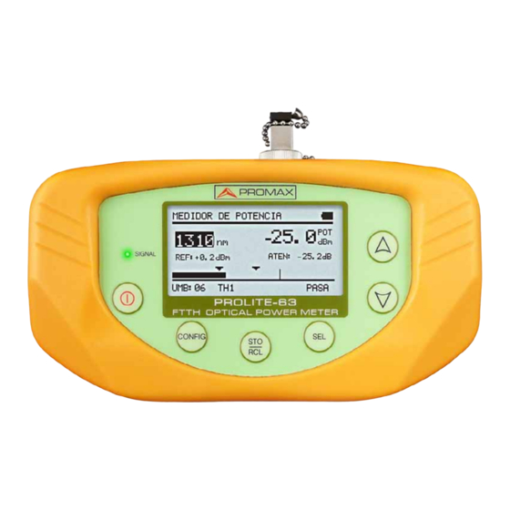
3 OPERATING INSTRUCTIONS Descriptions of Controls and Elements Front Panel Figure 1. 1 Signal detection LED: COLOURS: GREEN (value within thresholds). RED (value below threshold). ORANGE (value above threshold). 2 CURSOR keys with several functions according to the screen: Main Menu Screen: It moves the cursor over the functions. Function Screen: It shows the available values in the selected field. -
Page 13: Operating Instructions
Operating Instructions Main functions of the PROLITE-63 are accesible through the main menu, which you can access at by pressing the button CONFIG Figure 2. MENU screen. OPTICAL POWER METER (OPM): ► It measures optical power at the input in the whole infrared band (1100-1700) and allows you to take a reference value to measure from it. -
Page 14: Setup Mode
3.2.1 SETUP Mode This menu allows you to edit some basic parameters such as time, hour and language among others. To access the SETUP menu: Press the button CONFIG Press [5] until pointing at SETUP. Press CONFIG [2] or SEL [4] to get into the SETUP menu. -
Page 15: Optical Power Meter Function (Opm)
(1100 nm - 1700 nm). Under the situation of laboratory, LANs, WANs and CATV as well as longdistance optical network, the Optical Power Meters, together with PROMAX stabilized laser sources, can be used to identify optic fibre, measure optical attenuation, verify continuity and evaluate fibre link transmission quality. - Page 16 Press SEL or CONFIG to get into this function (see figure below). Figure 4. OPTICAL POWER METER. Next are described each one of the fields on screen: Wavelenght at which it is measuring. Available wavelenght are 1310, 1490, 1550 and 1625 nm. Reference value from which is calculated the relative losses.
-
Page 17: Optical Loss Test Set Function
Absolute optical signal power at the selected wavelenght. Absolute measurement mode represents the absolute signal power value in dBm (dB referred to 1 mW). Power measure is right only when the measured input It is an arrow which indicates if the value exceeds (arrow pointing up) or does not arrive (arrow pointing down) to the minimum levels in order to be graphically represented. - Page 18 Figure 5. OPTICAL LOSS TEST SET Screen. The display is divided into three equal rows. Each row shows measurements for each wavelenght. Next are described each one of the fields on screen: The SIGNAL LED indicates the status of the signal with respect to the threshold values.
-
Page 19: Threshold Configuration Mode
Absolute optical power of the signal at the corresponding wavelenght. Absolute measurement mode is the absolute power of signal in dBm (dB referred to 1mW). To navigate through the editable fields on the screen press SEL . The selected field changes to shaded. To edit a threshold group of values, select it and press To capture a new reference value, select the current reference value and press both keys... -
Page 20: Logger Function
To modify the threshold values: Press SEL to move along the parameters. To change a parameter, it must be shaded. Once it is shaded it can be modified by using the arrows. Once changes are made, press again SEL to get out from editing the parameter. - Page 21 To move between loggers press To take a logger press again STO/RCL . Then the message “Saving Logger” appears on screen and the logger is updated with the current date and hour. To consult a logger, press SEL . From this screen you can move between registers by pressing .
-
Page 22: Connecting To A Computer
Connecting to a computer This instrument allows you to be connected to a personal computer via USB in order to download registers and to update firmware. For more information see next chapter about PROLITE-63 control software. January 2014... -
Page 23: Control Software Prolite-63
4 CONTROL SOFTWARE PROLITE-63 Description This software is an application that allows a computer and the instrument PROLITE-63 to communicate. It allows you to download and view dataloggers from the instrument and configure some other parameters. It also allows upgrading the instrument. -
Page 24: Installation
It also puts a shortcut on the desktopand on the menu Start \ Program. Double click on the shortcut icon PROLITE-63 on the desktop to run the program. In the section “Operation Instructions” is explained in detail the program operation. -
Page 25: Connection Between Prolite-63 And Pc
4.4.1 Connection between PROLITE-63 and PC The connection between PROLITE-63 and PC is done via the data transmission cable USB (mini – USB) supplied with the instrument. Connect the USB connector to a free USB port of your PC. Connect the cable to the mini-USB port of the PROMAX instrument. - Page 26 When the instrument connects to the PC, the instrument shows the message "Synchronizing USB with PC" (Figure 12.). Figure 12. If the instrument detects the control program is not running will give the message "PC software is not detected" (Figure 13.-). The program must be started before connecting the instrument.
-
Page 27: Instructions For Using The Control Software
5 INSTRUCTIONS FOR USING THE CONTROL SOFTWARE Start Follow next steps in order to start using the PROLITE-63 Control Software: Check the PROLITE-63 is ON. Check connection between PROLITE-63 and computer. Run the program by double clicking on the icon PROLITE-63 which is located on the desktop. - Page 28 Below this box there are a series of buttons that allow you to perform various operations with loggers.. 5. When the instrument PROLITE-63 is identified at the USB port, it shows on screen some data about it such serial number and model.
-
Page 29: Main Window
Main window The main window, as shown in the figure below, has several different areas which are detailed next: Figure 15. Main window. Menu Bar There are the menus of the program (See section 6.3). Language in use It shows the flag identifying the selected language. Active function selection tab There are four tabs corresponding to each one of the two functions that are available at the program. - Page 30 If the connection fails you see next figure: Figure 17. Connection disabled. Logger Display Window It appears data loggers that have been selected at the Logger Selection Window. Logger Options It shows all the options you can do with loggers. To perform any of this options you have just to click on it.
-
Page 31: Menu Bar
Loggers selection Window It appears all loggers loaded from the instrument or from the PC. If you want to view, print or make any operation on them you have to check the box next to the logger. Menu bar Menu bar has these options: File: ►... -
Page 32: Loggers
5.3.2 Loggers Options of this menu are: Optical Loss Test Set (OLTS). ► Optical Power Meter (OPM). ► When clicking on any of these options, you active the window corresponding to that option, so you can carry out different actions on this function, such as import data, view loggers, make reports, etc. -
Page 33: Language
The option Set to Time allows you to synchronise time from the computer to the instrument. VERY IMPORTANT Before proceeding with the upgrade to verify that the battery is charged PROMAX. PROMAX not disconnect the USB port while you are upgrading. 5.3.6... -
Page 34: Specifications
6 SPECIFICATIONS Detector type InGaAs. Calibrated Wavelength 1310 nm, 1490 nm, 1550 nm and 1625 nm. Power measurement range From -60 dBm to +10 dBm. Wavelength measurement range 1100nm – 1700 nm. Accuracy ± 0.25 dB Resolution 0.1. Memory Storage 200 registers. - Page 35 1x DC-272 Protective cover. 1x CA-05 Mains cord CEE-7. 1x CC-41 Data Transfer Cable USB to PC. Wrist Strap. CD-ROM PROLITE-63. Adaptor's Kit (SC, FC and ST) 1x DG0136 Guide Reference rapide. OPTIONAL ACCESORIES 1x DC-270 Transport suitcase. RECOMMENDATIONS ABOUT THE PACKING It is recommended to keep all the packing material in order to return the instrument, if necessary, to the Technical service.
-
Page 36: Maintenance
7 MAINTENANCE This part of the manual describes the maintenance procedures and the location of faults. Instructions for returning by mail Instruments returned to repair or calibrate, either within or out of the guarantee period, should be send with the following information: Name of the Company, name of the contact person, address, phone number, receipt (in the case of coverage under guarantee) and a description of the problem or the service required. -
Page 37: Not Replaceable Fuses By User
7.2.2 Not replaceable fuses by user F001: FUS 2,5 A T 125 V F002: FUS 7 A T 125 V January 2014... -
Page 38: Appendix A: Application Note
Before initiating the network attenuation measurement process, it is advisable to register first the power measurement generated by the light source in combination with a PROLITE-63 and saving them in the memory. By this way when measuring later the attenuation of the optical network, the PROLITE-63 will indicate directly the value of the attenuation. -
Page 39: January
Connect the light source to the power level meter by means of an optical fibre patch cord, joined by a SC adaptor. Configure the PROLITE-63 to measure only at the wavelengths: 1310 nm, 1490 nm and 1550 nm, by means of the function ATTENUATION TEST (see that section on the PROLITE-63 user’s manual). - Page 40 PROMAX ELECTRONICA, S. L. Francesc Moragas, 71-75 08907 L’HOSPITALET DE LLOBREGAT (Barcelona) SPAIN Tel. : 93 184 77 00 * Tel. Intl. : (+34) 93 184 77 02 Fax : 93 338 11 26 * Fax Intl. : (+34) 93 338 11 26 http://www.promaxelectronics.com...
Need help?
Do you have a question about the PROLITE-63 and is the answer not in the manual?
Questions and answers