Table of Contents
Advertisement
Quick Links
Advertisement
Table of Contents

Related Manuals for Promax Prolite-50


Summary of Contents for Promax Prolite-50
- Page 1 PROLITE-50/51/52 OPTICAL REFLECTOMETER (OTDR) - 0 MI2119 -...
-
Page 2: Safety Notes
SAFETY NOTES Read the user’s manual before using the equipment, mainly SAFETY RULES paragraph. The symbol on the equipment means SEE USER’S MANUAL. In this manual may also appear as a Caution or Warning symbol. WARNING AND CAUTION statements may appear in this manual to avoid injury hazard or damage to this product or other property. - Page 3 SAFETY RULES * The safety could not be assured if the instructions for use are not closely followed. * This is a class I equipment, for safety reasons plug it to a supply line with the corresponding ground terminal. * When using some of the following accessories use only the specified ones to ensure safety.
- Page 4 Symbols related with safety: Descriptive Examples of Over-Voltage Categories Cat I Low voltage installations isolated from the mains. Cat II Portable domestic installations. Cat III Fixed domestic installations. Cat IV Industrial installations.
-
Page 5: Table Of Contents
Menu Bar of PROLITE-50/51/52 ..........4-14 4.1.2 Battery Recharge Status ............4-15 4.2 Trace Measurement ................4-15 4.2.1 Parameter Configuration on PROLITE-50/51/52 on Menu Bar..4-16 4.2.2 Trace Measurement - Auto ............4-36 4.2.3 Trace Measurement - Manual ............. 4-37 4.2.4... -
Page 7: General
PROLITE-50/51/52 is more helpful for field operation. It can help to check the qualification of optical fibre chain circuit on a regular basis. For the purpose of future maintenance, transmission quality and condition of optical fibre need to be recorded and stored, which includes measurement of optical path, total loss, and loss of all tie-ins and connectors. - Page 8 PROLITE-50/51/52 basic applications: • Measure the length of optical fibre and cable. • Measure the distance between two points on optical fibre and cable. • Locate faults and ruptures of optical fibre and cable. • Display distribution curve of optical fibre and cable loss.
-
Page 9: Description Of Controls Elements
2 DESCRIPTION OF CONTROLS ELEMENTS Patch panel Figure 1.- Patch panel. Power on and charge indicators. Connector for AC power supply adapter. Interface of connexion: USB interface in order to connect the equipment to a PC. It allows transferring the traces stored to the PC to be analysed later. -
Page 10: Keypad Functions
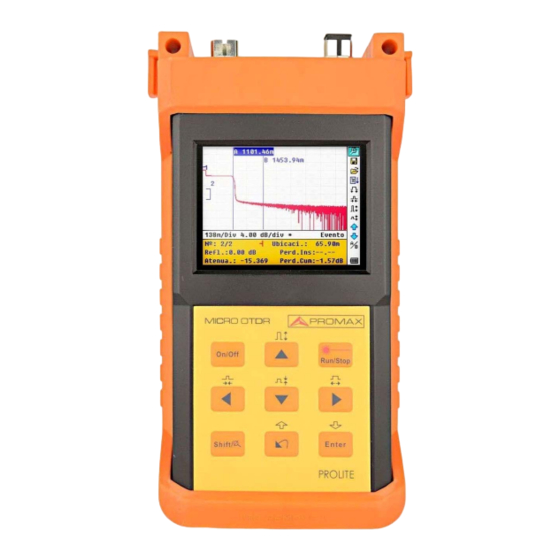
Keypad Functions Figure 2.- Operation Interface of PROLITE-50/51/52. On / Off for system. Main functions: They allow moving within different menus well increase/decrease the value of configuration parameters. Pressing [ ] previously in the visualisation display of trace, allows to increase/decrease vertically the size of the trace. - Page 11 Pressing it previously allows executing the secondary functions. Also it serves to cancel the zoom in / zoom out actions for trace visualisation, which has been done. Main functions: This key allows going forward through pages from Help, cancelling the selected operation, exiting from configuration menu and changing between information windows from visualised trace.
-
Page 12: Basic Information Of Prolite-50/51/52
The magnitude of reflection depends on the difference between IOR and the smoothness of boundary. PROLITE-50/51/52 sends out a light pulse into connected optic fiber, and receive reflections of events and backward scattering power of pulse in time. - Page 13 Reflection Events When some pulse energy is scattered, reflection events happen. When reflection event occurs, peak shows on trace, as shown in figure 3. Figure 3.- Reflection Event. Non-reflection Events Non-reflection events happen at certain points where there is some optic loss but no light scattering.
-
Page 14: Measurement Application Of Prolite-50/51/52
Inspection Event PROLITE-50/51/52 sends off a light pulse into the optic fiber to be inspected, and then receive returning light signals, and starts calculating the “event” distance. The farther the distance is, the longer time need for scattered light to be received by the instrument. Event distance can be calculated according to the time of receiving events signals. -
Page 15: Trace Display Screen Of Prolite-50/51/52
Trace Display Screen of PROLITE-50/51/52 Trace displays on PROLITE-50/51/52 screen, as shown in figure 5. Figure 5.- Trace Display Screen 3.4.1 Trace Display of PROLITE-50/51/52 This window displays the trace after one measurement. Definition of Trace: After one measurement, reflection power diagram will be displayed as distance function. -
Page 16: Information Window Of Prolite-50/51/52
3.4.2 Information Window of PROLITE-50/51/52 Contents of this window: measurement parameters, events list, marker A/B and analysis parameters. Measurement Trace Parameters Important measurement and analysis parameters always display in the information window, as shown in figure 7 and 8: Figure 7.- Measurement Trace Parameters Figure 8.- Analysis Trace Parameters... - Page 17 Event List To indicate the location of events inspected. Any defined posts will be displayed in event list, for example, non-reflection event like welding points and reflection event like connectors, as shown in figure 9. Figure 9.- Events List Event sequence No. Four types Fiber beginning;...
- Page 18 Accuracy Marker is used to mark and analyze a single event, trace section and distance. Distance, attenuation, loss at marker or between markers will be displayed in information of markers, as shown in figure 10. Figure 10.- Information of Marker A/B The following parameters are measured between marker A and B.
-
Page 19: Trace Measurement Process
Instructions on Graphic User Interface (GUI) After power on, power on interface displays on the LCD, as shown in figure 11: S hinewayTech PROLITE-50 pal m O TD R- XXXX --- Versión 3.0 --- - - - Ver si on 3. 0 - - - >>>>>>>>>>>>>>>>>>>>>... -
Page 20: Menu Bar Of Prolite-50/51/52
4.1.1 Menu Bar of PROLITE-50/51/52 On the right side of LCD display is located vertically the menu bar of the PROLITE-50/51/52 in form of icons. Press [ ] and [ ] in order to move the cursor along the menu of options. Select the function by pressing [... -
Page 21: Battery Recharge Status
Make sure that the optical fiber or cable is not in use and there is no laser beam in the fiber before testing via PROLITE-50/51/52. Otherwise, it may result in imprecise test trave, even permanent damage for the PROLITE-50/51/52. -
Page 22: Parameter Configuration On Prolite-50/51/52 On Menu Bar
Parameter Configuration on PROLITE-50/51/52 on Menu Bar 4.2.1 Correct parameter configuration is a necessity for accurate measurement; therefore, necessary configuration must be performed before using the instrument. Use [ ] and [ ] to highlight , parameter configuration, then press [ ],as shown in figure 13 and figure 14. - Page 23 Following screen shows a list of adjustable parameters: Parameter Definition of Parameter Range Length of optic fiber relevant to the trace. Pulse Width Width of laser pulse sending out from OTDR to optic fiber. Average Time To select suitable testing time. Wavelength To select laser wave length for measurement.
- Page 24 Range Configuration Generally, range will be set according to actual length of optic fiber, so as to insure the accuracy of measurement. Under the parameters configuration menu, use [ ] and [ ] to select “Range”; Press [ ] to access. Use [ ] and [ ] to select adequate range;...
- Page 25 Pulse Width Configuration The selection of pulse width affects the dynamic range and resolution of measurement trace. With narrow pulse width, there will be higher resolution and smaller dead zone, however, the dynamic range will be decreased. On the contrary, wide pulse width can bring higher dynamic range and measure comparatively long distance, but resolution and dead zone will be affected.
- Page 26 Average Time Configuration Average time will affect the SNR directly. The longer the average time is, the higher SNR is, as well as dynamic range. Therefore, in case of measurement of long-distance optic fiber, long average time should be selected in order to review events at long-distance end.
- Page 27 Wavelength Configuration The PROLITE-50/51/52 works with different wavelengths (see specifications). Under parameter configuration, use [ ] and [ ] to highlight ”wavelength”; press [ ] to change wavelength, as shown in figure 18. Figure 18- Wavelength Configuration 4-21 July 2016...
- Page 28 While under Real time Mode, press key [ ] to stop, otherwise it will measure all along. Under Averaging Mode, PROLITE-50/51/52 will average the data within the measure time which is set by user. While exceeding the set time, it will stop automatically and display the result. Generally, we suggest Averaging Mode.
- Page 29 VFL- Visual Fault Locator (For PROLITE-52 only) Under parameter configuration, use [ ] and [ ] to highlight “VFL”; according to different demand, press [ ] to select CW, 1Hz or off, Press [ to exit When VFL is on, [ ] icon will be displayed under icon, which is in the right menu bar.
- Page 30 Refractive index setting (IOR) IOR is a key factor to affect the speed of laser transmission in optic fiber; and in this case, IOR configuration has direct impact on the accuracy of measurement. Generally speaking, the IOR parameter is provided by optic fiber manufacturer, and it can be set to the accuracy of four digits after decimal point between 1.0 - 2.0.
- Page 31 Scattering Coefficient Configuration Scatter coefficient determines the value of backward scatter power. The configuration affects the calculation of reflection value. Under parameter configuration, use [ ] and [ ] to highlight ”Scatter Coefficient”; press [ ] to enter, as shown in figure 23. Press [ ] to exit.
- Page 32 Non Reflection Threshold Configuration This configuration has direct impact on the listing of insertion loss events. Only events GE this threshold will be listed. Under parameter configuration, use [ ] and [ ] to highlight “Non reflection threshold”; press [ ] to enter, as shown in figure 24.
- Page 33 Reflection Threshold Configuration This configuration has direct impact on reflection events listing. Only reflection events GE this threshold will be displayed in events list. Under parameter configuration, use [ ] and [ ] to highlight “Reflection Threshold”; press [ ] to enter, as shown in figure 25. Press [ ] to exit.
- Page 34 End Threshold Configuration This threshold is the end threshold of optic fiber. If the end threshold equals 3.0 dB, then the first event with insertion loss GE 3 dB will be considered as the end of the optic fiber. If the value is set to 0 dB, there will be no end threshold. Under parameter configuration, use [ ] and [ ] to highlight ”End...
- Page 35 Delete File This function is designed to delete saved traces. Under parameter configuration, use [ ] and [ ] to highlight “Delete file” press [ ] to enter, as shown in figure 27. Press [ ] to exit. Figure 27.- Delete File Press [ ] and [ ] to choose the files to be deleted, then press [...
- Page 36 Time Configuration Time configuration is used to change system time. Under parameter configuration, use [ ] and [ ] to highlight ”Time”; press ] to change, as shown in figure 28. Press [ ] to exit. Figure 28.- Time Configuration Use [ ] and [ ] to adjust the position of highlights;...
- Page 37 Auto Off Configuration This function is designed for conserving battery power. If auto off is on, the instrument will auto power off within 5 minutes of idleness. Under parameter configuration, use [ ] and [ ] to highlight ”Auto off”; press [ ] toswitch, as shown in figure 29.
- Page 38 Contrast Adjustment of LCD display The contrast of LCD has been adjusted. And users can adjust the contrast according to their own visual habits. Under parameter configuration, use [ ] and [ ] to highlight ”LCD Contrast”; press [ ] to adjust, as shown in figure 31. Press [ ] to exit.
- Page 39 Color Mode Setting This configuration allows choosing between four combinations of different colours. Use [ ] and [ ] to select “Colour mode”, press [ ] to choose between the different combinations of colour. Press [ ] to quit. Figure 32.-. Color Mode Setting Use [ ] and [ ] to highlight suitable color mode setting;...
- Page 40 Defaults Set This function is used to set PROLITE-50/51/52 parameters to factory settings. Those parameters include: range, pulse width, average time, IOR, non reflection threshold, reflection threshold, end threshold, and scatter coefficient. Under parameter configuration, use [ ] and [ ] to highlight “Load defaults”;...
- Page 41 Help Users can get the quick reference via “Help“ menu. Under parameter configuration, Use [ ] and [ ] to highlight “Help”; Press ] to enter, as shown in figure 34. Press [ ] to exit. Figure 34.- Help 4-35 July 2016...
-
Page 42: Trace Measurement - Auto
Steps for Auto measurement: Parameter configuration: for detailed operations, please refer to “Parameter Configuration on Prolite-50 Menu Bar”. Set range to “AUTO”. Measure: press [ ] to start measurement, and the interface is as shown in figures 35 and 36. -
Page 43: Trace Measurement - Manual
But at the end of measurement, the trace will be final, as shown in figure 37. Figure 37.- Trace Measurement of PROLITE-50/51/52 4.2.3 Trace Measurement - Manual If the operators have full knowledge of measured optic fiber, they can set accurate parameters, and achieve optimal measurement results. -
Page 44: Information Window
4.4.2 Prolite-50/51/52 information window. Switch between Information Window Items 4.3.1 Under GUI of figure 37, press [ ] and the items of information window will display in circulation: measurement parameter → analysis information → Event list →... -
Page 45: Cursors
4.3.3 Cursors The PROLITE-50/51/52 has two cursors (A and B) available which can be displaced throughout the trace in order to provide specific information about each point. In order to exchange the active cursor to use [ ] and [... -
Page 46: Save Trace
In order to increase the trace horizontally to keep pressed [ ] and later In order to decrease the trace horizontally to keep pressed [ ] and later In order to increase the trace vertically to keep pressed [ ] and later In order to decrease the trace vertically to keep pressed [ ] and later Save Trace... -
Page 47: Browse Saved Traces
Save file: use [ ], [ ], [ ] and [ ] to highlight “OK”, press ] to save. Cancel saving file: use [ ], [ ], [ ] and [ ] to highlight “cancel”, press [ ] to cancel the operation of “save file”. Delete alphanumeric character: use [ ], [ ], [... -
Page 48: Upload Saved Traces
Install the software, and run. Power off PROLITE-50/51/52. Connect PROLITE-50/51/52 to PC through USB interface cable. Power on PROLITE-50/51/52, and upload data with the software. Figure 40.- Upload Saved Traces NOTE: Make sure the instrument is power off when connecting to PC through USB data cable;... -
Page 49: Specifications
5 SPECIFICATIONS Wavelength (nm) PROLITE-50 1310/1550 nm. PROLITE-51 1310/1550/1625 nm. PROLITE-52 1625 nm. Dynamic Range (dB) PROLITE-50 24 dB. PROLITE-51 38/37/37 dB. PROLITE-52 37 dB. Event Dead Zone PROLITE-50 10 m. PROLITE-51 1.5 m. PROLITE-52 1.5 m. Attenuation Dead Zone PROLITE-50 25 m. - Page 50 Power Supply AC 100 V / 240 V 50 / 60 Hz. Carrying Bag. 0 DG0226 Quick User's Guide. Communication software. (Latest version of software available on the download PROMAX website area). Communication with PC Cable. AD500 Adapter ST (Optional). RECOMMENDATIONS ABOUT THE PACKING It is recommended to keep all the packing material in order to return the equipment, if necessary, to the Technical Service.
-
Page 51: Maintenance
NOTES FOR MAINTENANCE OF BATTERIES IN THE INSTRUMENT: In order for the PROLITE-50/51/52 (including the batteries) to meet specifications, the storage temperature should be within 0 ºC to 40 ºC. And the instruments should be stored in low humidity environments. -
Page 52: Cleaning Of Interfaces
Procedure of replacing the clock battery To take off cover of the battery cell. To remove the battery NiMH to the equip. Under the battery is the backup battery for internal cloack. Replace if necessary it must be of type. Button cell 3V Li CR1220. Connect and replace the NiMH battery. - Page 53 Safety Instructions to be Followed before Cleaning Make sure the instrument is power off when cleaning. Any operations contradict to the instructions may result in dangerous laser injuries. Make sure laser source is off, when clean any optic connectors. When the instrument is in operation, please always avoid looking directly into optic output.
-
Page 54: Calibration Requeriments
Figure 40.- Structure of Flange Calibration Requeriments Calibration of the instrument is recommended every two years. Please contact our representatives or nearby customer service centers for proper calibration. Clearing Recommendations CAUTION To clean the cover, take care the instrument is disconnected. CAUTION Do not use scented hydrocarbons or chlorized solvents.
Need help?
Do you have a question about the Prolite-50 and is the answer not in the manual?
Questions and answers