Table of Contents
Advertisement
Available languages
Available languages
Quick Links
Advertisement
Chapters
Table of Contents

Related Manuals for Promax PROLITE-50


Summary of Contents for Promax PROLITE-50
- Page 1 PROLITE-50 REFLECTÓMETRO ÓPTICO (OTDR) OPTICAL REFLECTOMETER (OTDR) - 0 MI1388 -...
- Page 3 NOTAS SOBRE SEGURIDAD Antes de manipular el equipo leer el manual de instrucciones y muy especialmente el apartado PRESCRIPCIONES DE SEGURIDAD. El símbolo sobre el equipo significa "CONSULTAR EL MANUAL DE INSTRUCCIONES". En este manual puede aparecer también como símbolo de advertencia o precaución.
- Page 5 SUMARIO CONTENTS Manual español................English manual ................
-
Page 7: Table Of Contents
5.1.2 Estado de carga de la batería..............22 Proceso de medida ................... 23 5.2.1 Configuración de parámetros en la barra de menú del PROLITE-50 ..24 5.2.2 Medida de la traza - Auto................39 5.2.3 Medida de trazas - Manual ................. 41 5.2.4... - Page 8 MANUAL DE INSTRUCCIONES. PROLITE-50 6. MANTENIMIENTO....................47 Mantenimiento de las baterías ................47 Limpieza de las interfaces................. 49 Requerimientos de calibración ................51 Recomendaciones de limpieza ................. 51...
-
Page 9: General
ópticas. Por tanto, el PROLITE-50 es una herramienta muy útil para la fabricación de fibras ópticas, su instalación y mantenimiento. El principio de funcionamiento del PROLITE-50 consiste en revisar los “fenómenos”... - Page 10 MANUAL DE INSTRUCCIONES. PROLITE-50 El PROLITE-50 se caracteriza por: • Aplicaciones básicas: a) Medida de la longitud de la fibra óptica. b) Medida de la distancia entre dos puntos de la fibra. c) Localización de fallos y discontinuidades en fibras ópticas.
-
Page 11: Especificaciones
MANUAL DE INSTRUCCIONES. PROLITE-50 1.1 Especificaciones Margen Dinámico (dB) 24/24. 1310 / 1550 ±20. Longitud de onda (nm) Tipo de Fibra Monomodo. Escalas seleccionables (km) 1.3 / 2.5 / 5 / 10 / 20 / 40 / 80 /120. 30 ns / 100 ns / 275 ns / 1 µs / 2.5 µs. - Page 12 MANUAL DE INSTRUCCIONES. PROLITE-50 CONDICIONES AMBIENTALES DE FUNCIONAMIENTO Operación Uso interior, altitud hasta 2000m. 0 °C a +40 °C Margen de temperatura ambiente Humedad relativa Máx 80 % , sin condensación -10 °C a +70 °C Temperatura de almacenamiento CARACTERÍSTICAS MECÁNICAS...
-
Page 13: Prescripciones De Seguridad
MANUAL DE INSTRUCCIONES. PROLITE-50 2. PRESCRIPCIONES DE SEGURIDAD 2.1 Generales Este equipo puede ser utilizado en ambientes con Grado de Polución 1. Al emplear cualquiera de los siguientes accesorios debe hacerse sólo con los tipos especificados a fin de preservar la seguridad: Alimentador AL-005. - Page 14 MANUAL DE INSTRUCCIONES. PROLITE-50 Símbolos relacionados con la seguridad: CORRIENTE CONTINUA CORRIENTE ALTERNA ALTERNA Y CONTINUA TERMINAL DE TIERRA TERMINAL DE PROTECCIÓN TERMINAL A CARCASA EQUIPOTENCIALIDAD MARCHA PARO DOBLE AISLAMIENTO (Protección CLASE II) PRECAUCIÓN (Riesgo de choque eléctrico) PRECAUCIÓN VER MANUAL FUSIBLE Página 6...
-
Page 15: Ejemplos Descriptivos De Las Categorías De Sobretensión
MANUAL DE INSTRUCCIONES. PROLITE-50 2.3 Ejemplos Descriptivos de las Categorías de Sobretensión Cat I Instalaciones de baja tensión separadas de la red. Cat II Instalaciones domésticas móviles. Cat III Instalaciones domésticas fijas. Cat IV Instalaciones industriales. 01-2006 Página 7... - Page 16 MANUAL DE INSTRUCCIONES. PROLITE-50 Página 8 01-2006...
-
Page 17: Descripción De Mandos Y Elementos
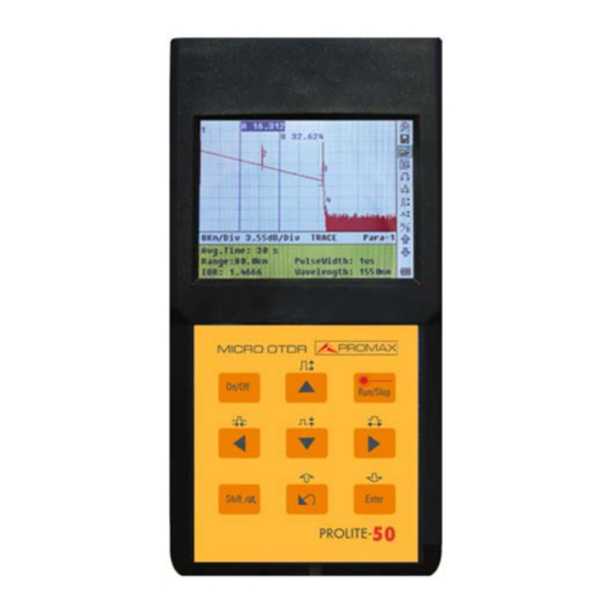
MANUAL DE INSTRUCCIONES. PROLITE-50 3. DESCRIPCIÓN DE MANDOS Y ELEMENTOS 3.1 Panel de conexiones. POWER CHARGE RS-232 13.8V/1.2A Figura 3.1.- Panel de conexiones. [1] [2] Indicadores de encendido y carga. [3] [5] Interfaces de conexión Interfaces RS-232 y USB para la conexión del equipo con el PC. -
Page 18: Teclado De Funciones
MANUAL DE INSTRUCCIONES. PROLITE-50 3.2 Teclado de funciones. Figura 3.2.- Interfaz de funcionamiento del PROLITE-50 Encendido / apagado del equipo. [2] [4] Funciones principales: Permiten desplazarse dentro de los diferentes menús asi como aumentar / disminuir el valor de parámetros de configuración. - Page 19 MANUAL DE INSTRUCCIONES. PROLITE-50 [3] [8] Funciones principales: Permiten desplazarse dentro de los diferentes menús asi como mover horizontalmente los cursores a lo largo de la traza. Pulsando previamente [ ] en la pantalla de visualización de la traza, permite aumentar / disminuir horizontalmente el tamaño de la traza.
- Page 20 MANUAL DE INSTRUCCIONES. PROLITE-50 Página 12 01-2006...
-
Page 21: Información Básica Del Prolite-50
(los eventos se refieren a fallos provocados por uniones, conectores, y curvaturas cuyos cambios en la transmisión pueden medirse). Su conexión no destructiva del extremo para mediciones rápidas convierte al PROLITE-50 en una herramienta indispensable para la fabricación, construcción y mantenimiento de fibras ópticas. -
Page 22: Eventos De Reflexión
MANUAL DE INSTRUCCIONES. PROLITE-50 4.2.1.1 Eventos de reflexión Cuando algún pulso de energía se dispersa, aparecen los fenómenos de la reflexión. Al producirse la reflexión, aparecen picos en la traza como muestra la figura 4.1. Figura 4.1.- Eventos de reflexión 4.2.1.2 Eventos de no reflexión. -
Page 23: Inspección De Eventos
MANUAL DE INSTRUCCIONES. PROLITE-50 4.2.1.3 Inspección de eventos El PROLITE-50 transmite un pulso de luz en la fibra óptica a inspeccionar, y entonces recibe las señales de luz de retorno, comenzando a calcular la distancia del “evento”. Cuanto mayor es la distancia, mayor tiempo precisa la luz dispersada para llegar hasta el instrumento. -
Page 24: Pantalla De Visualización De Trazas Del Prolite-50
MANUAL DE INSTRUCCIONES. PROLITE-50 4.4 Pantalla de visualización de trazas del PROLITE-50 La traza se visualiza en la pantalla del PROLITE-50, como se muestra en la figura 4.3. Ventana de Trace visualización Display Barra de Menu Window de Trazas Menú... -
Page 25: Ventana De Información Del Prolite-50
MANUAL DE INSTRUCCIONES. PROLITE-50 4.4.2 Ventana de información del PROLITE-50. Contenido de esta ventana: parámetros de medida, lista de eventos, marcador A/B y análisis de parámetros. 4.4.2.1 Parámetros de Traza de Medidas Los parámetros de análisis y medida importantes siempre aparecen en la ventana de información, como muestra la figura 4.5 y 4.6:... -
Page 26: Lista De Eventos
MANUAL DE INSTRUCCIONES. PROLITE-50 Para la definición de los items de la figura 4.6 (fecha, umbral de reflexión, umbral de no reflexión, coeficiente de dispersión), por favor consultar los parámetros de configuración. 4.4.2.2 Lista de eventos Para indicar la localización de los eventos inspeccionados. Cualquier fenómeno definido se mostrará... -
Page 27: Precisión
MANUAL DE INSTRUCCIONES. PROLITE-50 4.4.2.3 Precisión El marcador se utiliza para señalar y analizar un único evento, la sección de la traza y la distancia. La distancia, atenuación, pérdidas en el marcador o entre marcadores se visualizará en la información de los marcadores, como aparece en la figura 4.8. - Page 28 MANUAL DE INSTRUCCIONES. PROLITE-50 Página 20 01-2006...
-
Page 29: Proceso De Medida De Trazas
MANUAL DE INSTRUCCIONES. PROLITE-50 5. PROCESO DE MEDIDA DE TRAZAS Trazas 5.1 Introducción a la Interficie Gráfica de Usuario (GUI) Al encender el equipo, se visualiza en el LCD una pantalla de arranque como muestra la figura 5.1: S hinewayTech... -
Page 30: Barra De Menú Del Prolite-50
MANUAL DE INSTRUCCIONES. PROLITE-50 5.1.1 Barra de menú del PROLITE-50 En la parte derecha de la pantalla LCD se encuentra verticalmente la barra de menú del Prolite-50 en forma de iconos. Pulsar [ ] y [ ] para desplazarse a lo largo del menú. -
Page 31: Proceso De Medida
Asegúrese que la fibra óptica o el cable no se están utilizando y que no inciden fuentes de luz en el láser antes de medir con el PROLITE-50. De otro modo, podrían obtenerse medidas incorrectas o incluso un daño permanente al PROLITE-50. -
Page 32: Configuración De Parámetros En La Barra De Menú Del Prolite-50
MANUAL DE INSTRUCCIONES. PROLITE-50 5.2.1 Configuración de parámetros en la barra de menú del PROLITE-50 Una configuración de parámetros correcta es necesaria para conseguir medidas precisas; en consecuencia, es necesario llevar a cabo la configuración antes de utilizar el equipo. - Page 33 MANUAL DE INSTRUCCIONES. PROLITE-50 En esta pantalla se muestran los siguientes parámetros configurables: Parámetros Definición de parámetros Escala Longitud de la fibra óptica relevante para la traza Anchura del pulso láser que transmite el OTDR a la Anchura de Pulso fibra óptica...
- Page 34 MANUAL DE INSTRUCCIONES. PROLITE-50 Ra n g e Aut o Au t o Au t o Aut o 1. 3km Pu l s e Wi d t h 1. 3 km Av e . T i me 2. 5km 2. 5 km...
- Page 35 MANUAL DE INSTRUCCIONES. PROLITE-50 Ra n g e Aut o 3 0 n s 3 0 n s Aut o Pu l s e Wi d t h 100ns 100 ns Av e . T i me 275ns 275 ns 1.
- Page 36 3 min. La configuración por defecto es 30 s. • Configuración de la “Longitud de Onda” (Wavelength). El PROLITE-50 trabaja con dos longitudes de onda: 1310 nm y 1550 nm. En la configuración de parámetros, utilizar [ ] y [ ] para seleccionar ”wavelength”...
- Page 37 Existen dos tipos de modos de medida: Promediado (Averaging) y Tiempo Real (Real Time). En el modo de tiempo real, el PROLITE-50 registra medidas en tiempo real a través del conector para la fibra exterior y restaura la traza medida. Cuando...
- Page 38 MANUAL DE INSTRUCCIONES. PROLITE-50 • Configuración del índice de refracción (IOR) El IOR (Índice de Refracción) es un factor clave que afecta a la velocidad de la transmisión láser en una fibra óptica; y en este caso, la configuración del IOR tiene un impacto directo en la precisión de las medidas.
- Page 39 MANUAL DE INSTRUCCIONES. PROLITE-50 Ra n g e Aut o Aut o Pu l s e W i d t h Av e . T i me W a v e l e n g t h 1550 nm Me a s . Mo d e...
- Page 40 MANUAL DE INSTRUCCIONES. PROLITE-50 Utilizar [ ] y [ ] para ajustar la posición de los campos resaltados; utilice ] y [ ] para cambiar los dígitos. Después de configurarlos, pulsar Enter para confirmar. NOTA: El valor por defecto es 0.20 dB.
- Page 41 MANUAL DE INSTRUCCIONES. PROLITE-50 • Configuración del umbral de finalización (End Threshold). Este umbral es el umbral final de la fibra óptica. Si el umbral final es de 3.0 dB, entonces el primer evento con pérdida de inserción GE de 3 dB deberá ser considerado como el final de la fibra óptica.
- Page 42 MANUAL DE INSTRUCCIONES. PROLITE-50 Ra n g e Aut o Aut o Pu l s e Wi d t h Se l e c t f i l e: 0 1 1 8/ 3 0 0 Av e . T i me 30 s Tr ace 001 .
- Page 43 MANUAL DE INSTRUCCIONES. PROLITE-50 Utilizar [ ] y [ ] para ajustar la posición del campo resaltado; utilizar [ ] para cambiar los dígitos. Después de configurarlo, pulsar [Enter] para confirmar. • Configuración del apagado automático (Auto Off). Esta función se ha diseñado para el ahorro de la carga de la batería. Si la autodesconexión está...
- Page 44 MANUAL DE INSTRUCCIONES. PROLITE-50 Av e . T i me Wa v e l e n g t h 1550 nm Me a s. Mo d e Av e r a g i n g I OR 1. 4659 Sc a t . Co e f .
- Page 45 MANUAL DE INSTRUCCIONES. PROLITE-50 • Configuración del modo de color (Color Mode). Esta configuración permite elegir entre cuatro combinaciones de colores diferentes. Usar [ ] y [ ] para seleccionar “Modo de color”, pulsar [Enter] para elegir entre las diferentes combinaciones de color. Pulsar [ ] para salir.
- Page 46 MANUAL DE INSTRUCCIONES. PROLITE-50 I OR 1 . 4659 Sc a t . Co e f . - 51. 50 dB Nr e f l . T h r e. 0 . 20dB Re f l . T h r e .
-
Page 47: Medida De La Traza - Auto
Figura 5.24.- Ayuda. 5.2.2 Medida de la traza - Auto La medida automática puede ser aplicada en el caso que la longitud de la fibra óptica no sea identificable. El PROLITE-50 selecciona automáticamente la escala de medida. Pasos para la medida automática: •... - Page 48 MANUAL DE INSTRUCCIONES. PROLITE-50 Ave . Ti m e 00 : 30 Ti m e Passed : 00 : 16 Figura 5.25.- Medida Ave . Ti m e 00: 30 Anal yzi ng ¡ - Ti m e Passed : 00: 30 Figura 5.26.- Medida...
-
Page 49: Medida De Trazas - Manual
1. 4659 W avel engt h : 1550 nm Figura 5.27.- Medida de la traza del Prolite-50 5.2.3 Medida de trazas - Manual Si el usuario tiene un gran conocimiento de las fibras ópticas medidas, puede introducir directamente los parámetros precisos y obtener unas medidas óptimas. -
Page 50: Medida De Trazas - Motivos De Errores En Las Medidas
A/B. Para más detalles en relación a la ventana de información, consultar el apartado 4.4.2 de la ventana de información del PROLITE-50. 5.3.1 Conmutar entre los ítem de la ventana de información. En la GUI de la figura 5.5, pulsar [ ] y los ítems de la ventana de información... -
Page 51: Cursores
MANUAL DE INSTRUCCIONES. PROLITE-50 5.3.3 Cursores El PROLITE-50 dispone de dos cursores (A y B) que pueden ser desplazados a lo largo de la traza proporcionando información específica en ese punto. Para conmutar el cursor activo utilizar [ ] y [ ] para seleccionar el icono , después pulsar... -
Page 52: Guardar Traza
MANUAL DE INSTRUCCIONES. PROLITE-50 • Para aumentar la traza horizontalmente mantener pulsado [ seguidamente [ • Para disminuir la traza horizontalmente mantener pulsado [ seguidamente [ • Para aumentar la traza verticalmente mantener pulsado [ seguidamente [ • Para disminuir la traza verticalmente mantener pulsado [ seguidamente [ 5.5 Guardar traza... -
Page 53: Visualización De Trazas Guardadas
MANUAL DE INSTRUCCIONES. PROLITE-50 • Guardar el archivo: utilizar [ ], [ ], [ ] y [ ] para seleccionar “OK”, pulsar [Enter] para guardar. • Cancelar la operación de guardar: utilizar [ ], [ ], [ ] y [ ] para seleccionar “cancel”, pulsar [Enter] para cancelar la operación de “guardar... -
Page 54: Descarga De Las Trazas Guardadas Al Pc
Instalar el software y ejecutarlo. • Apagar el PROLITE-50. • Conectar el PROLITE-50 al PC a través del cable de la interfaz RS232 o USB. • Encender el PROLITE-50, y cargar los datos mediante el software. El proceso completo se muestra en la figura 5.30. -
Page 55: Mantenimiento
NOTA: Notas para el mantenimiento de las baterías del instrumento: A fin que el PROLITE-50 cumpla las especificaciones (incluyendo las baterías) la temperatura de almacenamiento debe estar entre —10 °C y 30 °C. Los equipos deben almacenarse en condiciones de baja humedad. - Page 56 MANUAL DE INSTRUCCIONES. PROLITE-50 • Procedimiento para reemplazar la bateria. Retirar la tapa de la bateria situada en el panel posterior del equipo. Retire la bateria desconectándola del conector, y sustitúyala por una nueva. Bajo la bateria se encuentra la pila de apoyo para el reloj interno.
-
Page 57: Limpieza De Las Interfaces
MANUAL DE INSTRUCCIONES. PROLITE-50 6.2 Limpieza de las interfaces Los conectores ópticos deben mantenerse limpias. Debe utilizarse un alcohol especial para limpiar la salida óptica. Colocar siempre los tapones de protección contra el polvo cuando se prevea que el equipo no va ha ser utilizado durante un largo periodo de tiempo, manteniéndolos limpios. - Page 58 MANUAL DE INSTRUCCIONES. PROLITE-50 • Herramientas para la limpieza de interfaces y conectores a) Limpiador para fibra óptica (para limpieza de conectores ópticos). b) Bastoncillo limpiador para fibra óptica (para limpieza de las salidas ópticas). c) Tisú para la limpieza de fibras ópticas (para la limpieza de interfaces ópticos) d) Alcohol isopropílico.
-
Page 59: Requerimientos De Calibración
MANUAL DE INSTRUCCIONES. PROLITE-50 6.3 Requerimientos de calibración Se recomienda calibrar el instrumento cada dos años. Por favor, contacte con los distribuidores más próximos para una calibración correcta. 6.4 Recomendaciones de limpieza PRECAUCIÓN Para limpiar la caja, asegurarse de que el dispositivo está desconectado. - Page 60 MANUAL DE INSTRUCCIONES. PROLITE-50 Página 52 01-2006...
- Page 61 Descriptive Examples of Over-Voltage Categories ..........7 3. DESCRIPTION OF CONTROLS ELEMENTS............9 Patch panel ......................9 Keypad Functions....................10 4. BASIC INFORMATION OF PROLITE-50 ..............13 Principle of Prolite-50 ..................13 Basic definition and classification of events ............13 4.2.1 Events ......................
- Page 62 USER’S MANUAL. PROLITE-50 6. MAINTENANCE....................... 47 Maintenance of Batteries................... 47 Cleaning of Interfaces ..................49 Calibration Requeriments.................. 51 Cleaning Recommendations ................51...
-
Page 63: General
PROLITE-50 is more helpful for field operation. It can help to check the qualification of optical fibre chain circuit on a regular basis. For the purpose of future maintenance, transmission quality and condition of optical fibre need to be recorded and stored, which includes measurement of optical path, total loss, and loss of all tie-ins and connectors. - Page 64 USER’S MANUAL. PROLITE-50 PROLITE-50 feature by: • Basic applications: a) Measure the length of optical fibre. b) Measure the distance between two points on optical fibre. c) Locate faults and ruptures of optical fibre. d) Display distribution curve of optical fibre.
-
Page 65: Specifications
USER’S MANUAL. PROLITE-50 1.1 Specifications Dynamic Range (dB) 24/24. 1310 / 1550 ±20. Wavelength (nm) Fibre Type Single mode. Selectable Ranges (km) 1.3 / 2.5 / 5 / 10 / 20 / 40 / 80 /120. 30 ns / 100 ns / 275 ns / 1 µs / 2.5 µs. - Page 66 USER’S MANUAL. PROLITE-50 Environmental conditions Altitude Up to 2000m. From 0°C to 40 °C Temperature range Relative humidity Max 80%, without condensation -10 °C a +70 °C Storage temperature Mechanical features Dimensions 100 (W) x 196 (H) x 60 (D) mm Weight 0.87 Kg.
-
Page 67: Safety Rules
USER’S MANUAL. PROLITE-50 2. SAFETY RULES 2.1 General This is a class I equipment, for safety reasons plug it to a supply line with the corresponding ground terminal. When using some of the following accessories use only the specified ones to ensure safety. - Page 68 USER’S MANUAL. PROLITE-50 Symbols related with safety: DIRECT CURRENT ALTERNATING CURRENT DIRECT AND ALTERNATING GROUND TERMINAL PROTECTIVE CONDUCTOR FRAME TERMINAL EQUIPOTENTIALITY ON (Supply) OFF (Supply) DOUBLE INSULATION (Class II Protection) CAUTION (Risk of electric shock) CAUTION REFER TO MANUAL FUSE...
-
Page 69: Descriptive Examples Of Over-Voltage Categories
USER’S MANUAL. PROLITE-50 2.3 Descriptive Examples of Over-Voltage Categories Cat I Low voltage installations isolated from the mains. Cat II Portable domestic installations. Cat III Fixed domestic installations. Cat IV Industrial installations. 01-2006 Page 7... - Page 70 USER’S MANUAL. PROLITE-50 Page 8 01-2006...
-
Page 71: Description Of Controls Elements
USER’S MANUAL. PROLITE-50 3. DESCRIPTION OF CONTROLS ELEMENTS 3.1 Patch panel POWER CHARGE RS-232 13.8V/1.2A Figure 3.1.- Patch panel [1] [2] Power on and charge indicators. [3] [5] Interfaces of connexion RS-232 and USB interfaces in order to connect the equipment to a PC. -
Page 72: Keypad Functions
USER’S MANUAL. PROLITE-50 3.2 Keypad Functions Figure 3.2.- Operation Interface of Prolite-50 / Off for system. [2] [4] Main functions: They allow moving within the different menus as well as to increase/decrease the value of configuration parameters. Pressing [ ] previously in the visualisation display of trace, allows to increase/decrease vertically the size of the trace. - Page 73 USER’S MANUAL. PROLITE-50 [3] [8] Main functions: They allow moving within the different menus as well as to move the cursors horizontally throughout the plan. Pressing [ ] previously in the visualisation display of trace, allows to increase/decrease horizontally the size of the trace.
- Page 74 USER’S MANUAL. PROLITE-50 Page 12 01-2006...
-
Page 75: Basic Information Of Prolite-50
Information relating to distance is obtained through time information (that’s the reason why there is “time Domain” in the name of PROLITE-50). Fresnel reflection occurs at the boundary between two media of different IOR (for example, connections of faults, connectors, or optic fiber end). -
Page 76: Reflection Events
USER’S MANUAL. PROLITE-50 4.2.1.1 Reflection Events When some pulse energy is scattered, reflection events happen. When reflection event occurs, peak shows on trace, as shown in figure 4.1. Figure 4.1.- Reflection Event 4.2.1.2 Non-reflection Events Non-reflection events happen at certain points where there is some optic loss but no light scattering. -
Page 77: Inspection Event
USER’S MANUAL. PROLITE-50 4.2.1.3 Inspection Event PROLITE-50 sends off a light pulse into the optic fiber to be inspected, and then receive returning light signals, and starts calculating the “event” distance. The farther the distance is, the longer time need for scattered light to be received by the instrument. -
Page 78: Trace Display Screen Of Prolite-50
Definition of Trace: After one measurement, reflection power diagram will be displayed as distance function. This diagram is referred to as trace. Trace of PROLITE-50 displays measurement result in a graphic form. The y-axis stands for power, and the x-axis stands for distance, as shown in figure 4.4. -
Page 79: Information Window Of Prolite-50
USER’S MANUAL. PROLITE-50 4.4.2 Information Window of PROLITE-50 Contents of this window: measurement parameters, events list, marker A/B and analysis parameters. 4.4.2.1 Measurement Trace Parameters Important measurement and analysis parameters always display in the information window, as shown in figure 4.5 and 4.6: 12 Km / Di v 3. -
Page 80: Event List
USER’S MANUAL. PROLITE-50 For definitions of items in figure 4.6 (date, reflection threshold, non-reflection threshold, end threshold, scattering coefficient), please refer to parameter configuration. 4.4.2.2 Event List To indicate the location of events inspected. Any defined posts will be displayed in event list, for example, non-reflection event like welding points and reflection event like connectors, as shown in figure 4.7. -
Page 81: Precision
USER’S MANUAL. PROLITE-50 4.4.2.3 Precision Marker is used to mark and analyze a single event, trace section and distance. Distance, attenuation, loss at marker or between markers will be displayed in information of markers, as shown in figure 4.8. 12Km/ Di v 3. 50 dB/ Di v t r ace 1. t r c 15 : 20 A- B: 9. - Page 82 USER’S MANUAL. PROLITE-50 Page 20 01-2006...
-
Page 83: Processing Trace Measurement
USER’S MANUAL. PROLITE-50 5. PROCESSING TRACE MEASUREMENT Traces 5.1 Introduction to the Graphic User Interface (GUI) When power on the equipment, on the LCD appears a starting up screen as figure 5.1 shows: S hinewayTech PROLITE-50 pal m O TD R- XXXX --- Versión 3.0 ---... -
Page 84: Menu Bar Of Prolite-50
USER’S MANUAL. PROLITE-50 5.1.1 Menu Bar of PROLITE-50 On the right side of LCD display is located vertically the menu bar of the Prolite-50 in form of icons. Press [ ] and [ ] in order to move the cursor along the menu of options. -
Page 85: Trace Measurement Of Prolite-50
Make sure that the optical fiber or cable is not in use and there is no laser beam in the fiber before testing via PROLITE-50. Otherwise, it may result in imprecise test trave, even permanent damage for the PROLITE-50. -
Page 86: Parameter Configuration
USER’S MANUAL. PROLITE-50 5.2.1 Parameter Configuration Correct parameter configuration is a necessity for accurate measurement; therefore, necessary configuration must be performed before using the instrument. Use [ ] and [ ] to highlight , parameter configuration, then press Enter, or press [ ] to exit, as shown in figure 5.3 and figure 5.4. - Page 87 USER’S MANUAL. PROLITE-50 Following screen shows a list of adjustable parameters. Parameter Definition of Parameter Range Length of optic fiber relevant to the trace Width of laser pulse sending out from OTDR to optic Pulse Width fiber Average Time Time for a single measurement from beginning to end...
- Page 88 USER’S MANUAL. PROLITE-50 Ra n g e Aut o Au t o Au t o Aut o 1. 3km Pu l s e Wi d t h 1. 3 km Av e . T i me 2. 5km 2. 5 km...
- Page 89 USER’S MANUAL. PROLITE-50 Ra n g e Aut o 3 0 n s 3 0 n s Aut o Pu l s e Wi d t h 100ns 100 ns Av e . T i me 275ns 275 ns 1. 0us...
- Page 90 There are 5 levels of predefined average time: 15 s, 30 s, 1 min, 2 min and 3 min. The default setting is 30 s. • Wavelength Configuration The PROLITE-50 works with two wavelengths: 1310 nm and 1550 nm. Under parameter configuration, use [ ] and [ ] to highlight ”wave length”;...
- Page 91 ] to stop, otherwise it will measure all along. Under Averaging Mode, PROLITE-50 will average the data within the measure time which is set by user. While exceeding the set time, it will stop automatically and display the result. Generally, we suggest Averaging Mode.
- Page 92 USER’S MANUAL. PROLITE-50 Ra n g e Aut o Pu l s e Wi d t h Aut o Av e . T i me 30 s W a v e l e n g t h 1550 nm Me a s. Mo d e Av e r a g i n g 1.
- Page 93 USER’S MANUAL. PROLITE-50 Use [ ] and [ ] to adjust the position of highlights; use [ ] and [ ] to change the digits. After setting, press [Enter] to confirm. • Non reflection Threshold Configuration This configuration has direct impact on the listing of insertion loss events. Only events GE this threshold will be listed.
- Page 94 USER’S MANUAL. PROLITE-50 Aut o Ra n g e Aut o Pu l s e Wi d t h Av e . T i me W a v e l e n g t h 1550 nm Me a s. Mo d e...
- Page 95 USER’S MANUAL. PROLITE-50 • End Threshold Configuration This threshold is the end threshold of optic fiber. If the end threshold equals 3.0 dB, then the first event with insertion loss GE 3 dB will be considered as the end of the optic fiber.
- Page 96 USER’S MANUAL. PROLITE-50 Ra n g e Aut o Aut o Pu l s e Wi d t h Se l e c t f i l e: 0 1 1 8/ 3 0 0 Av e . T i me 30 s Tr ace 001 .
- Page 97 USER’S MANUAL. PROLITE-50 Use [ ] and [ ] to adjust the position of highlights; use [ ] and [ ] to change the digits. After setting, press [Enter] to confirm. • Auto off Configuration This function is designed for conserving battery power. If auto off is on, the instrument will auto power off within 5 minutes of idleness.
- Page 98 USER’S MANUAL. PROLITE-50 Av e . T i me Wa v e l e n g t h 1550 nm Me a s. Mo d e Av e r a g i n g I OR 1. 4659 Sc a t . Co e f .
- Page 99 • Defaults Set This function is used to set PROLITE-50 parameters to factory settings. Those parameters include: range, pulse width, average time, IOR, non reflection threshold, reflection threshold, end threshold, and scatter coefficient. Under parameter configuration, use [ ] and [ ] to highlight “Load defaults”;...
- Page 100 USER’S MANUAL. PROLITE-50 I OR 1 . 4659 Sc a t . Co e f . - 51. 50 dB Nr e f l . T h r e. 0 . 20dB Re f l . T h r e .
-
Page 101: Trace Measurement - Auto
Prolite-50 auto select adequate range for measurement. Steps for Auto measurement: • Parameter configuration: for detailed operations, please refer to 3.4.3.2, Parameter Configuration on Prolite-50 Menu Bar. Set range to”AUTO”. • Measure: press [ ] to start measurement, and the interface is as shown in figure 5.25 and 5.26. - Page 102 USER’S MANUAL. PROLITE-50 Ave . Ti m e 00 : 30 Ti m e Passed : 00 : 16 Figure 5.25.- Measuring Ave . Ti m e 00: 30 Anal yzi ng ¡ - Ti m e Passed : 00: 30 Figure 5.26.- Measuring...
-
Page 103: Trace Measurement - Manual
1. 4659 W avel engt h : 1550 nm Figure 5.27.- Trace Measurement of Prolite-50 5.2.3 Trace Measurement - Manual If the operators have full knowledge of measured optic fiber, they can set accurate parameters, and achieve optimal measurement results. -
Page 104: Trace Measurement - Reasons Of Measurement Failures
5.3 Information Window Items of information window: measurement parameters, analysis parameters, and information regarding marker A/B. For details regarding information window, please refer to 3.4.2 Prolite-50 information window. 5.3.1 Switch between Information Window Items Under GUI of figure 5.5, press [ ] and the items of information window will display in circulation: measurement parameter →... -
Page 105: Cursors
USER’S MANUAL. PROLITE-50 5.3.3 Cursors The PROLITE-50 has two cursors (A and B) available which can be displaced throughout the trace in order to provide specific information about each point. In order to ] to select the B exchange the active cursor to use [... -
Page 106: Save Trace
USER’S MANUAL. PROLITE-50 • In order to increase the trace horizontally to keep pressed [ ] and later [ • In order to decrease the trace horizontally to keep pressed [ ] and later [ • In order to increase the trace vertically to keep pressed [ ] and later [ •... -
Page 107: Browse Saved Traces
USER’S MANUAL. PROLITE-50 • Memory space: 118/300 means that total memory space is 300 files; it has already saved 118 files so far 5.6 Browse Saved Traces Use [ ] and [ ] to highlight , press [Enter] to confirm, as shown in figure 5.29. -
Page 108: Upload Saved Traces
• Connect PROLITE-50 to PC through RS232 (or USB) interface cable. • Power on PROLITE-50, and upload data with the software. The whole process is as shown in figure 5.30 Upl oad f i l es Pl ease wai t ! ( 4/ 8) 12Km/ Di v 3. -
Page 109: Maintenance
NOTE: Notes for maintenance of batteries in the instrument: In order for the PROLITE-50 (including the batteries) to meet specifications, the storage temperature should be within —10 °C to 50 °C. And the instruments should be stored in low humidity environments. - Page 110 USER’S MANUAL. PROLITE-50 • Procedure of replacing battery is as follows. To take off cover of the battery cell;. To remove the battery and draw out socket from the jack of rechargeable battery, then replace the battery;. To remove the RTC clock battery, then change it if necessary.
-
Page 111: Cleaning Of Interfaces
USER’S MANUAL. PROLITE-50 6.2 Cleaning of Interfaces Interfaces must be kept clean. Special alcohol may be used to clean optic output. Always replace protective dust caps when the unit is not being used, and keep the protective dust caps clean. - Page 112 USER’S MANUAL. PROLITE-50 • Tools for Cleaning Interfaces and Connectors a) Optic fiber cleaner (for cleaning of optic connectors). b) Optic fiber cleaning rod (for cleaning of optic outputs). c) Optic fiber cleaning tissue (for cleaning optic interfaces). d) Isopropyl alcohol.
-
Page 113: Calibration Requeriments
USER’S MANUAL. PROLITE-50 6.3 Calibration Requeriments Calibration of the instrument is recommended every two years. Please contact our representatives or nearby customer service centers for proper calibration. 6.4 Cleaning Recommendations CAUTION To clean the cover, take care the instrument is disconnected. - Page 114 USER’S MANUAL. PROLITE-50 Page 52 01-2006...
Need help?
Do you have a question about the PROLITE-50 and is the answer not in the manual?
Questions and answers