
Related Manuals for Promax OTDR Series


Summary of Contents for Promax OTDR Series
- Page 1 Multifunctional OTDR User’s Manual 99 Washington Street Melrose, MA 02176 Phone 781-665-1400 Toll Free 1-800-517-8431 Visit us at www.TestEquipmentDepot.com...
- Page 2 Multifunctional OTDR Test Platform...
-
Page 3: Warranty
Promax, as governed by international copyright laws. Warranty The material contained in this document is subject to change without notice. Promax makes no warranty of any kind with regard to this material, including, but not limited to, the implied warranties of merchantability and fitness for a particular purpose. - Page 4 PROMAX OTDR User’s Manual Environmental Conditions It is designed to operate at a maximum relative humidity of 95% and at altitudes of up to 2000 meters. Refer to the specifications tables. Before Applying Power Verify that the product is set to match the available line voltage, the correct fuse is installed, and all safety precautions are taken.
-
Page 5: Laser Safety Announcements
PROMAX OTDR User’s Manual Laser Safety Announcements OTDR is a laser instrument. Users should avoid looking directly into the optic output. Always avoid looking directly into the optical output port, when OTDR is working. And the use of microscope or magnifier should also be avoided, for the use of such devices can focus a highly intense beam onto the retina, which may result in permanent eye damage. -
Page 6: Agreement And Statement
PROMAX OTDR User’s Manual Agreement and Statement Button or menu: The operating units in GUI that can be clicked by stylus, indicated by letters in square brackets, e.g. [Setup] and [Start]. Key: The function key on front panel, indicated by letter or icon in quotation marks, e.g. -
Page 7: Table Of Contents
PROMAX OTDR User’s Manual Contents Notices ..........................iii Warranty ..........................iii ISO9001 Certification ......................iii Safety Instructions....................... iii Laser Safety Announcements ....................v Electric Safety Announcements...................v Agreement and Statement....................vi 1 General Information ......................1 1.1 Scope of this Manual .....................1 1.2 Introduction ........................1 1.3 Product Appearance.......................2... - Page 8 PROMAX OTDR User’s Manual 5.5 Trace Processing......................18 5.6 Available OTDR Module.....................18 6 Prepare to Use OTDR ......................19 6.1 Connectors Instruction....................19 6.2 Cleaning and Connecting to Optical Fiber ..............19 7 Test with OTDR ........................20 7.1 OTDR Quick Test......................20 7.2 Trace Processing......................21 7.3 Unsaved Traces......................21...
- Page 9 PROMAX OTDR User’s Manual 11.6 Switch And Move the Marked Point .................38 11.7 Fast Move the Markers Outside the Window ............39 11.8 Lock AB Markers ......................39 11.9 Zoom the Trace......................39 11.10 Cross Frame to Zoom the Trace................40 11.11 Use Zoom Toolbar to Zoom the Trace ..............40 11.11.1 Revert the Whole Trace View ................40...
- Page 10 21.11 Calibration Requirements ..................74 21.12 Shipment........................74 22 Troubleshooting ......................75 22.1 Common Problems and Solutions ................75 22.2 Trace Measurement Problems and Solutions.............76 22.3 Finding Information on Promax Website..............76 23 Warranty .........................77 23.1 Terms of Warranty .....................77 23.2 Exclusion ........................77 23.3 Warranty Registration....................77 23.4 Returning Instruments ....................77...
- Page 11 PROMAX OTDR User’s Manual FIGURES CONTENTS Fig. 1.1 Front View ........................2 Fig. 1.2 Front View ........................2 Tab. 1.1 Front Panel Indicators Introduction ..............2 Tab. 1.2 Front Panel Keys Instruction.................3 Tab. 1.3 Operating Parts Instructions .................4 Tab. 1.4 nterfaces on Platform Top..................4 ...
- Page 12 PROMAX OTDR User’s Manual Fig. 11.8 Check the trace parameters ................50 Fig. 12.1 Event location and loss information ..............52 Fig. 12.2 2-point Loss ......................53 Fig.12.3 5-point method ......................53 Fig. 12.4 Measure insertion loss in 5-point method ............54 Fig. 12.5 View attenuation....................55 ...
-
Page 13: General Information
PROMAX OTDR User’s Manual 1 General Information 1.1 Scope of this Manual Thank you for purchasing Promax instrument. Please read this manual carefully before using any of Promax series fiber-optic instrument. Always observe the warnings and cautions appearing throughout this manual. -
Page 14: Product Appearance
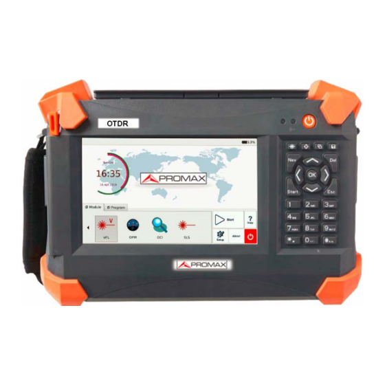
PROMAX OTDR User’s Manual 1.3 Product Appearance Fig. 1.1 Front View Power On/Off key is lower than other keys to avoid misoperation. Fig. 1.2 Front View 1.4 Front Panel Indicators Introduction Icon Status Meaning System off Green, constant System on... -
Page 15: Operating Parts Instructions
PROMAX OTDR User’s Manual Name Function Move left or extended function to be defined, please refer Help of current interface. Move right or extended function to be defined, please refer Help of current interface. Confirm button to confirm certain operations, please refer Help of current interface. -
Page 16: Instrument Interfaces Instructions
PROMAX OTDR User’s Manual Name Operation Description Right click Tab. 1.3 Operating Parts Instructions Stylus shouldn’t touch the screen insufficient, otherwise might cause unable to operating regularly Stylus shouldn’t touch the screen with too much force, otherwise might damage the LCD and touch screen. -
Page 17: Gui Icons Instruction
PROMAX OTDR User’s Manual Name Appearance Icon Description Visible Red Laser port PON Power Meter downstream input PON Power Meter upstream input Stabilized Light Source port Multi-wavelength Optical Power Meter port Tab. 1.5 Optical Ports The amount of connectors depends on module configuration, not all modules are equipped with abovementioned optical ports OTDR is a laser instrument. -
Page 18: Power Instruction
PROMAX OTDR User’s Manual Icon Status Operation Description Click Start selected function Enter Setup interface, including Click Interface style, Language System setting etc. Enter Help of current interface Click Enter “About” interface Click System off Click Tab. 1.6 GUI Icons Instruction 1.9 Power Instruction... - Page 19 PROMAX OTDR User’s Manual the current battery power is 75% of the total battery power. : Battery unplugged or connection is poor. : Power adaptor plugged. OTDR battery is rechargeable Li-ion battery. If unused for a long time, please charge the battery to 50%-70% before conservation.
-
Page 20: Basic Operation
PROMAX OTDR User’s Manual 2 Basic Operation 2.1 Foreword This part introduces the basic operation on the OTDR. Please read this manual carefully for optimal operation. Should you encounter any problems during operation, you are welcome to contact the technical staff of our company or representatives. -
Page 21: Adjust Lcd Brightness
PROMAX OTDR User’s Manual 2.4 Adjust LCD Brightness The LCD lightness is 4-level adjustable. Press button to toggle between different levels. When it is the minimum level and press the button, it will be the maximum brightness. 2.5 Start Application When OTDR is powered on, system will load the main program of Linux (Application software package) and enter main interface, as shown in Fig. -
Page 22: Common Settings And Special Settings
PROMAX OTDR User’s Manual 3 Common Settings and Special Settings 3.1 Main Setting Menu In setting menu, user can set up many settings, including language, power saving, and load default. Enter main setting menu: When power is on, press the [Setup] button to enter the setting menu, as shown below: Fig 3.1 Main Setting Menu... -
Page 23: Automatic Power Saving Setting
PROMAX OTDR User’s Manual 3.3 Automatic Power Saving Setting The feature is designed to save the battery power. When power is on, OTDR will automatically enter power saving mode after its idle time exceeds pre-set value. Setting Power Saving Mode: Click [Setup] to enter into setting menu. -
Page 24: Measurement Application Of Otdr
PROMAX OTDR User’s Manual optic fiber transmission features. It is mainly used to measure attenuation of a whole optic fiber chain and provide attenuation details relating to length, namely detect, locate and measure any event in optic fiber chain (Events refer to faults caused by splicing, connectors and bending). -
Page 25: Basic Definition And Classification Of Events
PROMAX OTDR User’s Manual 4.3 Basic Definition and Classification of Events Events refer to any abnormal points causing attenuation or sudden change of scattering power besides the normal scattering of optic fiber, which include all kinds of losses like bending, connections and ruptures. -
Page 26: Optic Fiber Link And Event Types
PROMAX OTDR User’s Manual Fig.4.2 Non-reflection Event 4.4 Optic Fiber Link and Event Types Optic fiber link and event type: Event Type Description Beginning of optic fiber link Reflection event Non-reflection event End of optic fiber link Tab.4.1 Optic fiber link and event type End of optic fiber can be identified through scanning the first loss event that is greater than end threshold. -
Page 27: Instruction Of Otdr Modules Of Otdr
PROMAX OTDR User’s Manual 5 Instruction of OTDR Modules of OTDR 5.1 Main Features of OTDR Module High dynamic range and short dead zones. Complete sampling under low noise, realize accurate low loss locating. Resolution is accurate to 10cm. -
Page 28: In-Service Mode And Normal Mode
PROMAX OTDR User’s Manual 5.2.3 In-service Mode and Normal Mode In-service Mode: Measure live fiber, which use 1625nm to test. This mode doesn’t affect the normal working wavelength in the fiber under test. Normal Mode: Use other wavelength except 1625nm (such as 1310nm, 1490nm, 1550nm and etc.) Make sure there is no laser transmitting in the fiber under test before testing. -
Page 29: Otdr Interface
PROMAX OTDR User’s Manual 5.3 OTDR Interface When power on, it will show the main menu automatically In main menu, select “OTDR module”, click [Start] button to enter OTDR user interface, as follows: Fig. 5.1 OTDR Main Interface 5.4 Icons Instruction in OTDR Interface... -
Page 30: Trace Processing
PROMAX OTDR User’s Manual Icon Description Move marker or marking point left/right Toggle between marking points Close trace Return to previous menu Return to previous menu Tab.5.1 Buttons and icons in OTDR main interface Not all icons are displayed in one interface, they can be seen in different functional interfaces. -
Page 31: Prepare To Use Otdr
PROMAX OTDR User’s Manual 6 Prepare to Use OTDR 6.1 Connectors Instruction The optical ports equipped on OTDR are FC/PC (Interchangeable SC, ST and LC) 6.2 Cleaning and Connecting to Optical Fiber To insure measurement accuracy, please clean and connect fiber properly before testing. -
Page 32: Test With Otdr
PROMAX OTDR User’s Manual 7 Test with OTDR 7.1 OTDR Quick Test 1. Check the connection between fiber and OTDR optical port, make sure it’s well connected. 2. Click [Start] icon or press button to start testing. 3. Click [Stop] icon or press button to stop testing. -
Page 33: Trace Processing
PROMAX OTDR User’s Manual 7.2 Trace Processing After test and automatic analysis is complete, event types will be displayed below the trace area; user can review all events information in events list which is on {Events} label. After test and automatic analysis is complete, user can save traces. Please refer to the “Save Trace”. -
Page 34: Open Saved Trace
PROMAX OTDR User’s Manual Save dialog window and options are shown below in Fig 7.2: Fig. 7.2 Save dialog window Title shows current folder path, shown 7.2: “\SDMMC_DISK\Traces\”. System will automatically enter newly created folder. After file is saved, file name will be displayed on left upper corner of trace display area. -
Page 35: Trace Viewing And Analysis Operation
PROMAX OTDR User’s Manual 2. In Multi-trace display mode, user can open and display up to four traces at the same time. Enable/disable Multi-trace display mode in OTDR Setup by checking/unchecking “Multi-trace” in Display Option. “.jpg” format trace can be also loaded to PC for viewing. -
Page 36: Information And Function Windows
PROMAX OTDR User’s Manual operation may not be successful. Please try several times to get used to it. Marker operation and re-analysis are not applicable to ‘.jpg“ format trace. For more information, please refer to “Trace Analysis and Event Operation”. -
Page 37: Upload Trace To Pc
PROMAX OTDR User’s Manual 3. When the analysis finished, events list will show the new results. Reanalyzing trace may cause added events are deleted, events revised are resumed, and events deleted come back etc. For more operation on events, please refer to “Trace Analysis and Event Operation”. -
Page 38: Testing Optical Fiber In Auto Mode
PROMAX OTDR User’s Manual 8 Testing Optical Fiber in Auto Mode 8.1 Instruction of Auto Testing Mode When don’t know the optical fiber length, can simply use the auto testing function to get the trace and analyze. After the auto mode started, OTDR will automatically estimate the optical fiber length, set sampling parameter, get trace and display the event list and etc. - Page 39 PROMAX OTDR User’s Manual detailed operation way, please refer to relative paragraph previous. When testing automatically, Range is “AUTO”. When setting the parameter, if the optical fiber parameter is not clear, can directly use the default value, but it may cause a bigger testing error.
-
Page 40: Testing The Optical Fiber In Manual Mode
PROMAX OTDR User’s Manual 9 Testing the optical fiber in Manual mode Manual mode can set various test parameters more precisely. The premise is know the general situation of optical fiber and then set parameters precisely and gets more ideal test result. -
Page 41: Otdr Display And Other Configuration
PROMAX OTDR User’s Manual Parameter Definition Also called reflectivity. Reflection events with insertion loss Reflection Threshold greater than this threshold will be displayed on trace. Also be called optical fiber end detecting threshold. The first event with insertion loss greater than this threshold is... -
Page 42: Range Configuration
PROMAX OTDR User’s Manual result after the testing finished. Under general condition, user chooses average mode will be ok. Operating instructions Real time mode and average mode are controlled by [Real time/Average] in {test setting}<test mode>. When the button highlight display “Average”, it means average mode; when button sag and display “Real time”, it means real time mode. -
Page 43: Averaging Time Configuration
PROMAX OTDR User’s Manual user to set. There will be different pulse width options according to different distance range. 9.7 Averaging Time Configuration Test times affects the test trace SNR, the longer test time, the higher SNR and get a bigger dynamic;... -
Page 44: Non-Reflection Threshold (Splice Loss Detecting Threshold) Setting
PROMAX OTDR User’s Manual 9.11 Non-reflection Threshold (Splice Loss Detecting Threshold) Setting This configuration has direct impact on the listing of insertion loss events. Only insertion loss event which is greater than this threshold will be listed. The default value is 0.20dB. -
Page 45: Use Otdr Test Fttx-Pon Network Optical Fiber Link
PROMAX OTDR User’s Manual 10 Use OTDR Test FTTx-PON Network Optical Fiber Link For FTTx-PON network optical fiber link, it’s different from normal optical fiber link; and there is branching unit in link. So, it needs to know and notes follow items when use this instrument to test FTTx-PON network. -
Page 46: Test Parameter Recommendation Value
PROMAX OTDR User’s Manual 10.4 Test parameter recommendation value End threshold Loss reference Recommend test Splitter type configuration reference value pulse width value 100ns,300ns ≥9dB 12dB 1:16 ≥12dB 15dB 100ns,300ns 300ns,1us 1:32 ≥15dB 18dB 300ns,1us 1:64 ≥18dB 21dB Tab. 10.1 Recommended parameter values for PON network optical fiber link... -
Page 47: Trace Analysis And Event Operation
PROMAX OTDR User’s Manual 11 Trace Analysis and Event Operation 11.1 Open Trace File Open trace file: 1. Press down [Open] in button column in OTDR surface. 2. Select the file need to be opened in the files dialog box. -
Page 48: Simultaneous Display Multi Traces
PROMAX OTDR User’s Manual 11.2 Simultaneous Display Multi Traces In order to let user compare trace files, OTDR support opening and displaying multi traces. When open multi trace, current trace is red, the icon in front of the file name is red, other icons are grey. -
Page 49: Switch And Move Markers
PROMAX OTDR User’s Manual The number on the Y axis shows the reflection power value (relative power) and its range. After get the trace, the trace display parameters can be revised (like grid line and zoom window screen). Please refer to the paragraphs of “trace display parameters configuration”... -
Page 50: Switch And Move The Marked Point
PROMAX OTDR User’s Manual In the buttons area on the bottom of surface, click [ ] to switch between A and After select Markers, continuously click [ ] or [ ] to move Markers. After select marked point, click [... -
Page 51: Fast Move The Markers Outside The Window
PROMAX OTDR User’s Manual 11.7 Fast Move the Markers Outside the Window When magnify the trace, Markers may be positioned outside of the window. When the Markers on the left side outside the window, there will be a sign on the left margin of the window: A←... -
Page 52: Cross Frame To Zoom The Trace
PROMAX OTDR User’s Manual 11.10 Cross Frame to Zoom the Trace In the trace display area, magnify the traces by cross frame from upper left to lower right. In the trace display area, contract the trace from upper right to lower left. -
Page 53: Zoom Out Trace Horizontally
PROMAX OTDR User’s Manual 11.11.3 Zoom Out Trace Horizontally This function is to zoom out trace horizontally. Click to zoom out trace. 11.11.4 Zoom In Trace Vertically Click [ ] to Zoom in trace vertically. 11.11.5 Zoom out Trace Vertically Click [ ] to Zoom out trace vertically. - Page 54 PROMAX OTDR User’s Manual To move magnified trace window in the navigation window In the navigation window, can see the position of current window on the whole magnified trace. Click some place outside the magnified area in the navigation window, trace window will move to the place correspondingly.
-
Page 55: Operation Of Event Options
PROMAX OTDR User’s Manual 11.14 Operation of Event Options Event sheet lists all the events tested on the trace. Event can be defined as point where optical transmission occurred change. Events are constituted loss which caused by transmission, splice, connector or crack. If event was not in the certain threshold, it was defect event. -
Page 56: Display The Event On The Trace And Locate Event In Even Sheet
PROMAX OTDR User’s Manual 11.14.1 Display the Event on the Trace and Locate Event In Even Sheet Through rolling the event sheet, user can check the relative info about all events tested on the trace. When an event selected, there will be Markers appear on the trace which above the event. -
Page 57: Delete Event
PROMAX OTDR User’s Manual Add event: 1. Press[Add] on {Event} label; Fig. 11.3 Add event 2. Fill in the event information in the add event dialog window. Fig. 11.4 Add Event Dialog Window 3. Press [Enter] to save and back to main window after edit finished, the event will appear in the event list. -
Page 58: Analysis Detecting Threshold Configuration
PROMAX OTDR User’s Manual Important hint: The only way to recover the deleted items is to reanalyze the trace, like analyze new traces. Please refer to the part “analyze or reanalyze trace”. Delete event 1. Select the event need to be deleted 2. -
Page 59: Reanalyze The Trace
PROMAX OTDR User’s Manual Set analysis detecting threshold 1. Press [Setup] in the button area which in the lower right area to enter setting surface. 2. Set these parameters in the parameters analysis part. In the relative edit frame, enter value needed or press [Default] revert the default value. -
Page 60: Analyze The Optical Fiber In Specific Optical Fiber Link
PROMAX OTDR User’s Manual Reanalyze the trace: 1. In the [Event] options, press [Analysis], it will reanalyze the whole trace; 2. After analysis finished, the new analytic result will be listed in the event sheet. If user wished to find some new events or filter some events he didn’t pay attention, please change the analysis detecting threshold first and then to proceed the analysis. -
Page 61: Fig. 11.7 Options Of Test Display Area
PROMAX OTDR User’s Manual Zoom toolbar: It can display or hide the zoom icon area which on the right side; will get maximized trace display area after hide the zoom toolbar. The zoom toolbar is displayed under default status. -
Page 62: Set The Length Unit
PROMAX OTDR User’s Manual 11.19 Set the Length Unit In the OTDR parameters setting dialog box, select the length unit in the test display area options. The unit can be meter, feet or mile. The default length unit is meter. - Page 63 PROMAX OTDR User’s Manual Date: Date and time of test. Wavelength: Laser wavelength used for test. Pulse width: Laser pulse width used for sampling. Averaging time: Continuous sampling time. Range: Distance used for test. ...
-
Page 64: Manual Trace Analysis
PROMAX OTDR User’s Manual 12 Manual Trace Analysis User can use markers and zoom tools to measure splice loss, attenuation and reflection, or use markers to locate event position and relative power level. 12.1 Use Markers Click {Markers} label in OTDR main interface to activate markers. -
Page 65: Fig. 12.2 2-Point Loss
PROMAX OTDR User’s Manual System calculates real timely the loss between Marker A and B, and also calculates the insertion loss at Marker A or B. Insertion loss is calculated in 5-point method. 2-point method (A-B Loss): Insertion loss is calculated as shown in Fig. 12.2. -
Page 66: Fig. 12.4 Measure Insertion Loss In 5-Point Method
PROMAX OTDR User’s Manual When Marker B is selected, the screen will display the 4 marking points related to Marker B. The Markers and marking points can move separately. The procedure to apply 5-point method: 1. In the main interface of OTDR OTDR module, click “Markers” label;... -
Page 67: Measure Attenuation (2-Point And Lsa Method)
PROMAX OTDR User’s Manual The marking points on the left of the active marker cannot be moved the right and vice versa. The loss showed in the Event List is measured by 5-point method. 12.4 Measure Attenuation (2-point and LSA method) 2-point method measures the attenuation between Marker A and B calculated by all the loss over the distance between Marker A and B (Unit: dB/Km). -
Page 68: Measure Reflectance
PROMAX OTDR User’s Manual There should not be any event between Marker A and B when measuring attenuation with 2-point method. 12.5 Measure Reflectance Reflectance is the ratio of reflected power (Pr) to incident power (Pi) of an event (such as a connector). -
Page 69: Fig 12.6 Measure Reflectance
PROMAX OTDR User’s Manual Fig 12.6 Measure reflectance For non-reflection events, reflectance will show as “-----”。 - 57 -... -
Page 70: Trace File Management
PROMAX OTDR User’s Manual 13 Trace File Management User can save, open, rename and delete trace file after acquisition. User can save and open trace file in OTDR main interface. User can rename, copy, move and delete file in File Explorer. -
Page 71: Check Disk Space
PROMAX OTDR User’s Manual User can move, rename and delete files saved in SD card but the disk itself cannot be moved, renamed or deleted. For more information, please refer to the Help file on OTDR. Method two: User can connect OTDR to PC, OTDR will be recognized as a mobile device. -
Page 72: Print Otdr Report
PROMAX OTDR User’s Manual 14 Print OTDR Report User can manage saved trace files in OTDR and print report. For reference and report printing, it is necessary to manage and update trace information. 14.1 Trace Information After trace acquisition, user can add or update tested fiber information which includes: Cable ID, Fiber ID, Fiber Type, Start Location, End Location and Operator. -
Page 73: Fig. 14.1 Trace Information And Editing
PROMAX OTDR User’s Manual Fig. 14.1 Trace information and editing 2. Input trace information in the pop-up window. 3. Click [Save] button in OTDR main interface to save the trace again and the updated information will be saved with the trace file. -
Page 74: Otdr Module Built-In Stabilized Laser Source Ls100
PROMAX OTDR User’s Manual 15 OTDR Module Built-in Stabilized Laser Source LS100 Enter Module-SLS. interface is shown as Fig 15.1 Fig.15.1 “Wavelength”: Same as the wavelength of OTDR, wavelengths can be selectable. “Mode”: Select different modes at PCW, 1KHz, 2KHz, 1KHz+Flash, 2KHz+Flash. -
Page 75: Fig. 16.1 Optical Power Meter
PROMAX OTDR User’s Manual Fig. 16.1 Optical Power Meter After the setup, click [Start] button to start the measurement. Click [Stop] button to stop the measurement. The function icon turns red while switching on this function module. “Unit”: Shift between dBm and W. - Page 76 PROMAX OTDR User’s Manual OTDR sampling and cause permanent damage to the OTDR. OTDR built-in source: 1. Clean connector properly. 2. Connect tested fiber to OTDR port. 3. Click {Source/VFL} in OTDR main interface. 4. Select the suitable wavelength. 5. Select the modulation.
-
Page 77: Vfl Application
PROMAX OTDR User’s Manual 17 VFL Application The built-in VFL of OTDR module can shoot red laser into the tested fiber, the red laser will glow at the marco bend, breaking points and bare fiber end. The maximum detection range for OTDR VFL is over 5Km, it is a practical tool for fiber identification, detecting and highlighting breaks, tight bends, splices or defective connectors in optical fibers. -
Page 78: Oci (Optical Connector Inspector) Of Mci100
PROMAX OTDR User’s Manual 18 OCI (Optical Connector Inspector) of MCI100 MCI100 Optical Connector Inspector (OCI) can display connector surface enlarged view and find dirty or damaged connector. It is convent for the operator to view the connector and remove any hidden troubles,which may affect the transmission quality. -
Page 79: Focus Control
PROMAX OTDR User’s Manual Fig. 18.2 Measurement 5.Click [Stop] button or Re-Press “ ”(Start/Stop)button on OTDR front panel to stop the measurement. 6. Exit this OCI interface: Click the exit button in the upper left corner; it will back to the main interface. -
Page 80: View The Saved Image
PROMAX OTDR User’s Manual 18.4 View the saved Image 1. Click the file manger of main interface program. 2. Open the folder which saves the capture image. 3. Double click the capture image file which you want to view. 4. Press the [File] <OFF> to exit the file manager after you are finished. -
Page 81: Vpn Function
PROMAX OTDR User’s Manual 19 VPN Function User can select VPN function, as following: Fig. 19.1 VPN Function - 69 -... -
Page 82: File Management
PROMAX OTDR User’s Manual 20 File Management User can directly copy, move, rename and delete file or folder on OTDR. Files can also be exchanged between OTDR and external storage devices like USB flash disk, USB hard drive and PC. -
Page 83: Maintenance And Calibration
PROMAX OTDR User’s Manual 21 Maintenance and Calibration 21.1 Cleaning of Optical Interfaces Interfaces must be kept clean. Special alcohol may be used to clean optic output. Always replace protective dust caps when the unit is not being used, and keep the protective dust caps clean. -
Page 84: Cleaning Procedure
PROMAX OTDR User’s Manual Optic fiber cleaning rod (for cleaning of optic outputs) Optic fiber cleaning tissue (for cleaning optic interfaces) Isopropyl alcohol Cotton ball Paper tissue Cleaning brush Condensed air 21.5 Cleaning Procedure Screw off the cap of flange... -
Page 85: Charge Battery
PROMAX OTDR User’s Manual After the battery is used for some time, its capacity may not match charging status indication (e.g. charging indicator indicates full but OTDR may power off due to low battery), then battery calibration is necessary (Please refer to 20.9 Battery Calibration). -
Page 86: Calibration Requirements
PROMAX OTDR User’s Manual Please note if the power indicator on front panel is off before changing battery; make sure OTDR is completely off before changing battery. Only factory can change clock battery. 21.11 Calibration Requirements Calibration of OTDR is recommended every two years. Please contact our representatives or nearby customer service centers for proper calibration. -
Page 87: Troubleshooting
OTDR User’s Manual 22 Troubleshooting 22.1 Common Problems and Solutions Problem Possible Reason Solution Charge the battery. Change a new battery. Battery power run out Connect OTDR to external power supply. Power on failure External power supply Connect OTDR to external power is not connected supply. -
Page 88: Trace Measurement Problems And Solutions
OTDR User’s Manual with stylus OTDR indicates low Battery is not fully battery after battery is Re-calibrate the battery charged. fully charged Tab. 21.1 Common Problems and Solutions 22.2 Trace Measurement Problems and Solutions Problem Possible Reason Solution Try again with short pulse width Events are too close to ... -
Page 89: Warranty
A warranty registration card is included with the original shipment of equipment. Please take a few moments to fill out the card and mail or fax it to the local Customer Service Center of PROMAX to ensure proper initiation of your warranty term and scope of your warranty. -
Page 90: Contacting Customer Service
Be sure to ship to our local representative or directly to us in a reliable way. 23.5 Contacting Customer Service Please check our web site for updates to this manual and additional application information. If you need technical or sales support, please contact local PROMAX Customer Service. PROMAX ELECTRONICA S. L. - 78 -...
Need help?
Do you have a question about the OTDR Series and is the answer not in the manual?
Questions and answers