Table of Contents
Advertisement
Quick Links
Advertisement
Table of Contents

Related Manuals for Promax PROLITE-45


Summary of Contents for Promax PROLITE-45
- Page 1 PROLITE-45 Multi-functional OTDR User’s Manual PROMAX All rights reserved.
- Page 2 PROLITE-45 Multi-functional OTDR...
-
Page 3: Warranty
The battery is a consumable part and is not subject to the PROLITE-45 warranty. ISO9001 Certification Produced to ISO9001 International Quality System Standard as part of PROMAX, is objective of continually increasing customer satisfaction through improved process control. - Page 4 The external power supply for PROLITE-45 is DC 5V/2A. Do Not Operate in an Explosive Atmosphere Do not operate PROLITE-45 in the presence of flammable gases or fumes. Do Not Remove the Cover of Tester Operating personnel must not remove instrument covers. Component replacement and internal adjustments must be made only by qualified service personnel.
-
Page 5: Laser Safety Announcements
Laser Safety Announcements PROLITE-45 is a laser instrument. Users should avoid looking directly into the optic output. Always avoid looking directly into the optical output port, when PROLITE-45 is working. And the use of microscope or magnifier should also be avoided, for the use of such devices can focus a highly intense beam onto the retina, which may result in permanent eye damage. -
Page 6: Agreement And Statement
Agreement and Statement Button or Menu: The operating units in GUI that can be clicked by finger or capacitive pen, indicated by letters in square brackets, e.g. [Expert OTDR], [File Manager], etc. Key: The function key on front panel, indicated by letter or icon in quotation marks, e.g. -
Page 7: Table Of Contents
Contents Notices ..........................iii Warranty..........................iii ISO9001 Certification....................... iii Safety Instructions ......................iii Laser Safety Announcements ..................v Electric Safety Announcements..................v Agreement and Statement................... - 1 - 1General Information....................- 5 - 1.1 Scope of this Manual .................... - 5 - 1.2 Introduction ...................... - Page 8 5.2.1 Auto Mode and Manual Mode............. - 16 - 5.2.2Averaging Mode and Realtime Mode ..........- 17 - 5.3 OTDR GU Interface .................... - 17 - 5.4 Trace Processing ....................- 18 - 6 Prepare to Use OTDR ....................- 18 - 6.1Connectors Introduction ..................
- Page 9 19.10 Calibration Requirements ................- 41 - 19.11 Shipment ......................- 41 - 20 Troubleshooting ......................43 20.1 Common Problems and Solutions...............43 20.2 Trace Measurement Problems and Solutions............44 20.3 Finding Information on PROMAX Website............44 21 Warranty ........................44 21.1 Terms of Warranty....................44 21.2 Exclusion .........................45 21.3 Warranty Registration....................45 21.4 Returning Instruments ...................45...
-
Page 10: 1General Information
1General Information 1.1 Scope of this Manual Thank you for purchasing PROMAX instrument. Please read this manual carefully before using any of PROMAX fiber-optic instruments. Always observe the warnings and cautions appearing throughout this manual. This manual contains the necessary information for proper operation and maintenance of PROLITE-45, troubleshooting instructions as well as information regarding obtaining services. -
Page 11: Hardware Overview
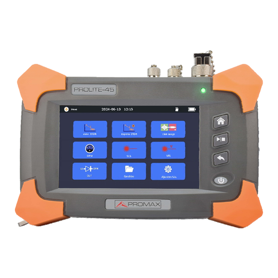
1.3Hardware Overview Front View Laser Indicator Home Button Start/Stop Escape Button Power ON/OFF button & Battery Charging Indicator Fig. 1.1 Front View Fig. 1.2 Top View 1.4 Front Panel Indicators Introduction Icon Status Meaning System off Power On/Off Indicator Orange, constant System on Battery Charging Red, constant... -
Page 12: Front Panel Keys Instruction
Icon Status Meaning Indicator Green, constant Charging complete The unit is off Red, constant Laser on Laser Indicator Laser off White, constant Light on Flashlight Light off 1.5 Front Panel Keys Instruction Name Function Home, back to main menu Press to start, press again to stop Exits the current menu Power on/off Press to power on system when system is off. - Page 13 Lighting in a dark environment LAN1 RJ45 Length /Sequence Test LAN2 RJ45 Tracker Tab. 1.4Interfaces on Top Panel ·Optical Ports PROLITE-45 is equipment with FC/PC connectors (Interchangeable SC, ST) Name Appearance Icon Description OTDR and Laser Source OTDR& LS port...
-
Page 14: Gui Icons Instruction
The battery power indicator displayed on LCD screen will turn red (Low battery) when the battery power is insufficient and PROLITE-45 may automatically power off. If unused for a long time, PROLITE-45 may not power on properly, please connect power adaptor and recharge the battery. - 9 -... -
Page 15: Use Of Rechargeable Battery
When PROLITE-45 is powered on and being charged, LCD will also indicate charging status. PROLITE-45 battery is rechargeable Li-ion battery. If unused for a long time, please charge the battery to 50%-70% before conservation. Keep the battery off from fire and intense heat; do not open or short circuit the battery. -
Page 16: Enter And Exit Power Saving Mode
2.3 Enter and Exit Power Saving Mode When power is on, user can set PROLITE-45 to power saving mode and return to normal status. In power saving mode, the LCD backlight will turn off. When power is on, PROLITE-45 will automatically enter power saving mode after its idle time exceeds pre-set value. -
Page 17: Common Settings And Special Settings
Launch OTDR program: 1. Select “Auto OTDR” or “Expert OTDR” in main menu. 2. Then press button Launch other functions such as OPM, SLS and VFL: 1. Click on relative icon in main menu such as SLS, OPM, and VFL. 2. -
Page 18: Select Language
Fig 3.1 System Settings Menu 3.2Select language Switching language: Click “Language” to select the required language. 4 Basic Information of OTDR 4.1 Principle of OTDR OTDR (Optical Time Domain Reflectmeter) is a measurement instrument for identifying optic fiber transmission features. It is mainly used to measure attenuation of a whole optic fiber chain and provide attenuation details relating to length, namely detect, locate and measure any event in optic fiber chain (Events refer to faults caused by splicing, connectors and bending).Its non-destructive, one-end connection... -
Page 19: Measurement Application Of Otdr
and this is called Rayleigh backward scattering, which actually provides attenuation details relating to length. Information relating to distance is obtained through time information (That’s the reason why there is “Time Domain” in the name of OTDR). Fresnel reflection occurs at the boundary between two media of different IOR (For example, connections of faults, connectors, or optic fiber end). -
Page 20: 1Reflection Events
Events can be classified as reflection events and non-reflection events. 4.3.1Reflection Events When some pulse energy is scattered, reflection events happen. When reflection event occurs, peak shows on trace, as shown below: Fig.4.1 Reflection Event 4.3.2 Non-reflection Events Non-reflection events happen at certain points where there is some optic loss but no light scattering. -
Page 21: Optic Fiber Link And Event Types
4.4 Optic Fiber Link and Event Types Optic fiber link and event type: Event Type Description Beginning of optic fiber link Reflection event Non-reflection event End of optic fiber link Tab.4.1 Optic fiber link and event type End of optic fiber can be identified through scanning the first loss event that is greater than end threshold. -
Page 22: 2Averaging Mode And Realtime Mode
Manual Mode: Advanced Mode which user can control all OTDR parameters to test. 5.2.2 Averaging Mode and Real Time Mode Real Time Mode: OTDR will undertake real time measurement for the connector of exterior fiber and refurbish the measure trace. Under real time mode, unless the user stops measurement, it will measure all along. -
Page 23: Trace Processing
5.4 Trace Processing The PC software in PROLITE-45 is for trace review and analysis on PC after acquisition without connecting to PROLITE-45. Trace processing includes: Trace editing Report Printing 6 Prepare to Use OTDR 6.1Connectors Introduction The default connector of PROLITE-45 is FC/PC (Interchangeable SC, ST) 6.2 Cleaning and Connecting to Optical Fiber... -
Page 24: 7Otdr Testing
When testing with OTDR, unless connected to specific optical port, please make sure there is no working laser in the fiber under test or it may cause incorrect result and even permanent damage to test instrument. Please not screw connectors too tight or it may damage fiber and optical port. -
Page 25: Trace Processing
User can stop testing any time, application will show all the information when test stops. After test is finished or interrupted by user, system will perform automatic analysis which takes about 5 seconds or longer before user can start a new test. -
Page 26: Auto Naming
7.4 Auto Naming System supports auto naming when saving traces. Procedure: 1. Click “File Manager”– “Save Setup”. 2. Enable/disable auto naming by selecting “Yes” or “No’ in ‘Auto Save’ setup. 3. User can edit auto naming rule by modifying file name prefix and sequence. 7.5 Open Saved Trace Click [File] button on the right in OTDR interface to open saved trace 7.6 Trace Viewing and Analysis Operation... -
Page 27: Upload Trace To Pc
Zoom out/in for different direction. Zoom Select and open saved trace. File Save trace Save Exit current interface. Exit Tab.7.1 Information and Function Windows Description Note: For detail information, please refer to “Trace Analysis and Event Operation”. 7.8 Upload Trace to PC On computer, user can manage the trace file flexibly. -
Page 28: The Procedures Of [Auto Otdr] Mode
Under [Auto OTDR] Mode, user can set follow parameters directly. The wavelength to be used for testing. Testing time span After Auto mode started, according to the situation of optical fiber link which connecting the equipment, application program will estimate the optimum setting automatically and it will need around 5s. -
Page 29: Expert Otdr]Mode Testing
9 [Expert OTDR] mode testing [Expert OTDR] mode can set various test parameters more precisely. The premise is to know the general situation of optical fiber and then set parameters precisely and gets more ideal test result. Correct parameters setting is the essential condition of optical fiber accurate measurement. -
Page 30: Otdr Test Parameters Configuration
9.2 OTDR test parameters Configuration Click [Setting] on the OTDR interface to enter. These testing parameters include: Measure Setup, Pass/Fail Setup and Analysis Setup. Parameter Definition IOR of optic fiber which affects the transmission speed of laser. Need to set separately according to working wavelength relatively Scatter Also be called back scatter, which affects backward scatter power Coefficient... -
Page 31: Pulse Width Configuration
Operation: Click and choose on the right distance required. 9.5 Pulse Width Configuration Pulse width selection affects the trace dynamic and resolution, select the smaller width to test can get a higher distance resolution and smaller dead zone, but the dynamic certainly damaged;... -
Page 32: Non-Reflective Threshold Setting
Generally speaking, the IOR parameter is provided by optic fiber manufacturer, and it can be set to the accuracy of four digits after decimal point between 1.0000 and 1.9999. 9.9 Non-reflective Threshold Setting This configuration has direct impact on the listing of insertion loss events. Only insertion loss event which is greater than this threshold will be listed. -
Page 33: Close Trace File
3. Click [Load] and the file opened. If click [Exit], the file can’t be opened and quit dialog box. Fig.10.1 Trace file opened Check or open “.bmp” format trace file, please click “File Manager” in main menu, or open on PC. 10.2 Close Trace File Close trace file: Click [Exit] button on the bottom right corner of the interface to close the trace... - Page 34 The number on the Y axis shows the reflection power value (relative power) and its range. After get the trace, the trace display parameters can be revised (like grid line and zoom window screen). Please refer to the paragraphs of “trace display parameters configuration”...
-
Page 35: Zoom The Trace
10.4 Zoom the Trace In order to check the event or detail in the trace, it needs to zoom the trace. System provides two ways to zoom the trace for easier use for the user: 1. Zoom the trace by cross finger touch, operation is smooth and fast 2. -
Page 36: Analysisthreshold Configuration
event. Fig.10.2 Events options As to every event in the even sheet, display follows info: Type: Different indicator used for different event type instruction. As to the detailed indicator instruction, please refer to the paragraphs previous. Number: Event number(one continuous number designated by OTDR application program). -
Page 37: Set The Length Unit
Change the reflection threshold (Reflection threshold): It can hide the fake reflection event caused by noise, turn the harmless reflection event to loss event or check the event which may cause damage to network and other optical fiber equipment. Change the finish threshold (optical fiber end threshold): It can analyze the important loss event(like breakpoint) and stop the event analysis after that event. -
Page 38: 11Trace File Management
2. User can open, rename, copy, move and delete file 3. After operation, click “Exit” back to main menu. 11.2 Connect to PC via. USB cable Connect PROLITE-45 to PC with USB cable, user can open, rename, copy, move and delete file on PC. - 33 -... -
Page 39: Link Image Otdr Testing
12 Link Image OTDR Testing The Link Image is a graphic display of each fiber link event; it can display the even with pass/fail analyze. It is more direct to show all the test result. Operation: Click [Link Image] in main menu as shown above. Testing setting and testing operation are the same as OTDR trace testing. -
Page 40: Optical Power Meter (Opm)
14 Optical Power Meter (OPM) Click [OPM] in main menu to enter optical power mete interface. “Auto zero”: This function provides an easy method of auto zero of power meter, which can be used to rectify the instrument’s power value under non-luminous state in daily testing. Put protective cap on optical power testing output, and ensure that the tie-in is completely airproof. -
Page 41: Optical Loss Test (Olt)
16 Optical Loss Test (OLT) Enter the loss test interface, click [ON] to perform loss test on the fiber loop as shown in Figure 16.1; The loss value will be displayed directly as shown in Figure 16.2. OPM PORT OTDR/SLS PORT Fig. -
Page 42: Rj45 Cable Testing
17 RJ45 Cable Testing RJ45 Cable Testing includes RJ45 sequence, RJ45 length and RJ45 Tracker. The procedures are as follows: Plug network cable into the LAN2 port and click test to test cable sequence and the length of the network cable. Plug network cable into the LAN1 port to track the cable with tool “Wire Tracker Receiver”... -
Page 43: System Settings
[Date & Time]: Click the “+”or“-” icon on the upper and lower sides of the year, month, day, hour and minute to adjust the corresponding time, and then click [Apply]. 18.2 Product Information It includes PROLITE-45 Hardware and software version information, etc. 18.3 Firmware Update: The procedures of firmware update are as follows: Connect PROLITE-45 with PC via USB cable. -
Page 44: Maintenance And Calibration
Be cautious of electric shock and make sure AC power is disconnected with PROLITE-45 before cleaning. Always use dry or moist soft cloth to clean the outside of PROLITE-45, and never clean the inside Please do not add any accessory to optic instrument or adjust PROLITE-45 at discretion. -
Page 45: Cleaning Tools
After the battery is used for some time, its capacity may not match charging status indication (e.g. charging indicator indicates full but PROLITE-45 may power off due to low battery), then battery calibration is necessary (Please refer to 19.8 Battery Calibration). -
Page 46: Charge Battery
19.7 Charge Battery Plug the charger to PROLITE-45 and power outlet, charging process automatically starts and finishes after battery is fully charged. 19.8 Battery Calibration After the battery is used for some time, the battery gauge may not be accurate, e.g. it indicates battery has run out but the battery can still provide power supply, or battery power is zero, but the battery power can last a long time. - Page 47 Please note following points to protect PROLITE-45 during shipment: Use original packing materials. Avoid excessive temperature and humidity change. Avoid direct exposure to sunlight. Avoid shock and vibration. - 42 -...
-
Page 48: Troubleshooting
Connect PROLITE-45 power indicator is off. external power supply. Brightness is not set Adjust brightness Screen display blurs properly. Restart PROLITE-45 and run the Application Problem error. application again. response Battery runs out. Change the battery. Operation time is Battery is not fully Charge the battery. -
Page 49: Trace Measurement Problems And Solutions
1. Type http://www.promaxelectronics.com in the address bar of browser. 2. Press the [Service and Support] TAB COBTROL. . 3.Click the FAQ, and then Associated with searchable list of questions. The web of PROMAX also provides the latest technical specifications of products. 21 Warranty 21.1 Terms of Warranty... -
Page 50: Exclusion
The warranty on your equipment shall not apply for defects resulting from the following: Unauthorized repair or modification Misuse, negligence, or accident PROMAX reserves the right to make changes to any of its products at any time without having to replace or change previously purchased units. 21.3 Warranty Registration A warranty registration card is included with the original shipment of equipment. -
Page 51: Contacting Customer Service
21.5 Contacting Customer Service Please check our web site (www.promaxelectronics.com) for updates to this manual and additional application information. If you need technical or sales support, please contact local PROMAX Customer Service. THANK YOU FOR CHOOSING PROMAX PROMAX - 46 -... - Page 52 PROMAX TEST & MEASUREMENT S.L.U. Francesc Moragas, 71-75 08907 L’HOSPITALET DE LLOBREGAT (Barcelona) SPAIN Tel. : 93 184 77 00 * Tel. Intl. : (+34) 93 184 77 02 https://www.promaxelectronics.com e-mail: promax@promaxelectronics.com...
Need help?
Do you have a question about the PROLITE-45 and is the answer not in the manual?
Questions and answers