Table of Contents
Advertisement
instruction manual
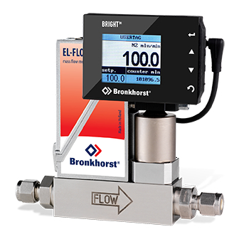
BRIGHT
Local colour TFT readout
and control module
Doc nr.: 9.17.048H
Date: 15-03-2017
ATTENTION:
Before installing and operating the instrument it is recommended to read the Short-form user manual or this
instruction manual. Not following the guidelines could result in personal injury and/or damage to the equipment.
Advertisement
Table of Contents

Related Manuals for BRONKHORST BRIGHT


Summary of Contents for BRONKHORST BRIGHT
- Page 1 BRIGHT Local colour TFT readout and control module Doc nr.: 9.17.048H Date: 15-03-2017 ATTENTION: Before installing and operating the instrument it is recommended to read the Short-form user manual or this instruction manual. Not following the guidelines could result in personal injury and/or damage to the equipment.
-
Page 2: Receipt Of Equipment
Warranty The products of Bronkhorst® are warranted against defects in material and workmanship for a period of three years from the date of shipment, provided they are used in accordance with the ordering specifications and the instructions in this manual and that they are not subjected to abuse, physical damage or contamination. -
Page 3: Table Of Contents
BRONKHORST® Table of content SCOPE OF THIS MANUAL ..........................4 Introduction ................................. 4 UNPACKING ..............................5 MOUNTING ..............................7 CONNECTING ..............................8 USER INTERFACE ............................9 Buttons ................................9 Power-up ................................9 Display ................................. 9 Measure readout ............................... 10 Custom readout 1 .............................. 10 Custom readout 2 .............................. -
Page 4: Scope Of This Manual
Four push-buttons at the right side of the device give access to a user-friendly menu. The bright 1.8” color display is clearly visible over a wide angle, due to state-of-the-art TFT-technology. -
Page 5: Unpacking
2 | UNPACKING 2 Unpacking BRIGHT module Mounting set IP40 T-part IP65 T-part Short 0.3m cable Extended mounting set Long cable for distance ... - Page 6 When returning material, always describe the problem and if possible the work to be done, in a covering letter. Take proper care of packing, if possible use the original packing box Important: Clearly note, on top of the package, the customer clearance number of Bronkhorst High-Tech B.V., namely: NL801989978B01 9.17.048 Page 6...
-
Page 7: Mounting
The BRIGHT comes with 4 different bolts. Please check the instruction above which bolt should be used. The design makes it possible to place the BRIGHT in other positions as shown above. The clip and the BRIGHT can be turned in angles of 90°. The BRIGHT can also be placed on the backside of the T-part. -
Page 8: Connecting
Cable wire diameters should be sufficient to carry the supply current and voltage losses must be kept as low as possible. Bronkhorst® recommends using their standard cables. These cables have the right connectors and if loose ends are used, these will be marked to prevent wrong connection. -
Page 9: User Interface
- Undo and Exit edit mode Top line Button CANCEL - Change information in right user-field 5.2 Power-up When power-up, the BRIGHT shows consecutive: Firmware version Bronkhorst logo Readout screen. 5.3 Display The display is divided into 4 areas, ‘measure readout’, ‘custom readout 1’, ‘custom readout2’... -
Page 10: Measure Readout
5 | USER INTERFACE 5.4 Measure readout This area shows the actual flow. The following parameters will affect the format of this readout: actual or percentage readout number of digits 5.5 Custom readout 1 This area can be enabled or disabled by the operator. When enabled, the operator can choose one of the following parameters to be shown: parameter... -
Page 11: Top Line
5 | USER INTERFACE 5.7 Top line The top line will show the USERTAG or the serial number of the connected instrument. 5.8 Edit Setpoint Setpoint can only be edited when the setpoint parameter is displayed in custom readout 1 or 2. Security settings can be set to avoid unauthorised access to the setpoint parameter. -
Page 12: Reset Counter
5 | USER INTERFACE button can be used to exit the edit mode and CANCEL cancel the changes. 5.9 Reset Counter The Counter can only be reset when the counter parameter is displayed in custom readout 2. Security settings can be set to avoid unauthorised access to the counter parameter. -
Page 13: Reset Alarm
5 | USER INTERFACE 5.10 Reset Alarm Alarm messages will be shown in the topline of the display and custom readout 2 will be selected automatically. Enter the edit mode by pressing . Use select ‘yes’ and press again to confirm. An alarm message will be occurring as long as the cause has not been removed/repaired. -
Page 14: Select Instrument
5 | USER INTERFACE button can be used to exit the edit mode and CANCEL cancel the changes. If you are not intending to reset the alarm, you can press to deactivate ‘Custom readout 2’. Check chapter CANCEL “Custom readout 2” on page 10 how to select another parameter in this readout. - Page 15 When an active node address is found, the BRIGHT will show the corresponding USERTAG or Serial Number in the topline.
-
Page 16: Settings Menu
6 | SETTINGS MENU 6 Settings menu From the readout screen press to enter the settings menu. Press to return to the readout screen. CANCEL Security settings can be set to avoid unauthorised access to this menu. For changing security settings see chapter “Security Settings”... -
Page 17: Readout Screen
6 | SETTINGS MENU 6.1 Readout screen From the readout screen you can edit the following settings: readout format, actual or percentage fluidset selection capacity 6.2 readout format Enter the readout settings screen and press to enter the edit mode of the readout option. Use select either ‘actual’... -
Page 18: Fluid Capacity
6 | SETTINGS MENU Press again to enter the edit mode of the fluid field. to select one of the available fluidsets. Press to confirm. Press 3x to return to the readout screen. CANCEL 6.4 fluid capacity From the readout screen, press to select ‘fluid selection’... -
Page 19: Controller Settings Screen
6 | SETTINGS MENU 6.5 Controller settings screen From the controller settings screen you can edit the following settings: setpoint slope time controller mode master address. PID settings response settings To enter the controller settings screen, select the controller option from the settings menu and press Take care when changing the controller settings. -
Page 20: Master Slave Settings
The following controller modes can be selected: selection description analog input Setpoint via analog input bus/rs232 Setpoint via bus or RS232 (BRIGHT) rs232 Setpoint via RS232 only (BRIGHT) fb ana slave Setpoint is factor of measure of master on the bus, factor is set by analog input. -
Page 21: Pid Controller Settings
You can find more information about these controller settings in the manual: 9.17.023 , This manual is available at the download section of our website: http://www.bronkhorst.com In the pid-controller settings screen you can select one of the PID parameters using the buttons. Press to enter the edit mode. -
Page 22: Controller Response Settings
6 | SETTINGS MENU Use the button to edit each character, press to select the next character. Press to cancel CANCEL the input and exit the edit mode without changes. By pressing after the final character you will confirm the value. The new value will be sent to the instrument. 6.10 Controller response settings The controller response settings can be used to fine tune the controller response. -
Page 23: Counter Settings Screen
6 | SETTINGS MENU In the controller response settings screen you can select one of the parameters using the buttons. Press to enter the edit mode. In the edit mode, use to change each character. Press to select the next character. Press to exit the edit mode without changes. -
Page 24: Set Counter Mode
9.17.023 , This manual is available at the download section of our website: http://www.bronkhorst.com 6.13 Set counter parameters To change one of the counter parameters use the button to select the parameter you want to change and press to enter the edit mode. -
Page 25: Set Setpoint At Counter Limit
6 | SETTINGS MENU 6.14 Set setpoint at counter limit You can program an automatic setpoint which will be activated when the counter limit is reached. To change this setpoint use button to select the setpoint change option and press to enter the counter setpoint settings screen. -
Page 26: Alarm Settings Screen
Select the alarm option from the settings menu and press You can find more information about these alarm settings in the manual: 9.17.023 , This manual is available at the download section of our website: http://www.bronkhorst.com 9.17.048 Page 26... -
Page 27: Set Alarm Mode
6 | SETTINGS MENU 6.16 Set alarm mode When entering the alarm settings screen the alarm mode is selected. Press to enter the edit mode. Select an alarm mode using . Press to exit the CANCEL edit mode without changes. Press to confirm your selection and exit the edit mode. -
Page 28: Set Setpoint At Alarm
6 | SETTINGS MENU 6.18 Set setpoint at alarm You can program an automatic setpoint which will be activated when an alarm situation occurs. To change this alarm setpoint use button to select the setpoint change option and press to enter the alarm setpoint settings screen. -
Page 29: Setup Menu
The sign in the upper right corner indicates that you can scroll through the menu screen items using the button. Scroll up and down to view: usertag* instrument serial number instrument model number instrument firmware version bright firmware version *) editable 9.17.048 Page 29... -
Page 30: Change Usertag
6 | SETTINGS MENU 6.21 Change usertag When entering the instrument info screen the usertag parameter is selected. Press to enter the edit mode. In the edit mode, use to change each character. Press to select the next character. Press to exit the edit mode without changes. -
Page 31: Bus Settings
6 | SETTINGS MENU 6.24 Bus settings When the operating instrument is connected to a bus system you can change the node address of this instrument. From the setup menu select the bus item and press to enter the bus settings screen. 6.25 Advanced menu From the advanced menu you can: change sensor filter settings... -
Page 32: Restore Instrument Settings
6 | SETTINGS MENU Press to start the sensor auto zero procedure. While the auto zero procedure is active, the BRIGHT will show the message ‘busy’. When finished, ‘auto zero ready’. Press any key to return to settings menu. 6.28 Restore instrument settings... -
Page 33: Security Settings
7 | SECURITY SETTINGS 7 Security Settings 7.1 Security modes The security settings screen allows you to define the access of the crucial menu items of the BRIGHT. For every item, you can choose the following access modes: item accessibility... -
Page 34: Change Password
7 | SECURITY SETTINGS The or signs in the upper right corner indicates that you can scroll this menu using the buttons to select more items. The accessibility of following items can be set: item accessibility edit setpoint edit mode of the setpoint in both custom readout 1 and 2 reset counter... -
Page 35: Reset Password
7 | SECURITY SETTINGS 7.5 Reset Password From the readout screen press both for 5 seconds till the ‘enter password’ display appears. Again press both for 5 seconds till the ‘reset password’ display appears. The ‘reset password’ display will show a 10 character long bht key. -
Page 36: Troubleshooting
LED’s” section in the manual “Operation instructions digital instruments (document nr. 9.17.023)”. This manual is available at the download section of our website: http://www.bronkhorst.com Contact Bronkhorst® local sales representative or send e-mail describing your problem to: support@bronkhorst.com 9.17.048... -
Page 37: Technical Data
9 | TECHNICAL DATA 9 Technical Data 1.8” colour TFT display with a 128x160 pixel resolution 100 MHz Processor 15..24Vdc 0.6W Power Consumption RS232 38k4 communication Operating temperature 0..50°C Dimensions: 73mm width x 50mm height x 23mm depth ... -
Page 38: Service
10 | SERVICE 10 Service For current information on Bronkhorst® and service addresses please visit our website: http://www.bronkhorst.com Do you have any questions about our products? Our Sales Department will gladly assist you selecting the right product for your application. Contact sales by e-mail: ... - Page 39 Subject to technical and optical changes as well as printing errors. The information contained in this document is subject to change at any time without prior notification. Bronkhorst High-Tech B.V. reserves the right to modify or improve its products and modify the contents without being obliged to inform any particular persons or organizations.
Need help?
Do you have a question about the BRIGHT and is the answer not in the manual?
Questions and answers