
Related Manuals for Contec PT-310LS


Summary of Contents for Contec PT-310LS
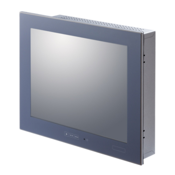
- Page 1 IPC Series PANEL-PC 310 Series Fanless, ARM Cortex-A8, SD, 12.1inch User’s Manual CONTEC CO., LTD.
-
Page 2: Check Your Package
Warranty Certificate Serial Number Label The user's manual, software manual * 1 for this product is available as a PDF file through CONTEC’s Web site. The user's manual provides such information as hardware settings, functions for each component settings. Refer to it as necessary PT-310LS-AC353111: Please refer to the software manual (Japanese version). -
Page 3: Copyright
No part of this document may be copied or reproduced in any form by any means without prior written consent of CONTEC CO., LTD. CONTEC CO., LTD. makes no commitment to update or keep current the information contained in this document. -
Page 4: Table Of Contents
Table of Contents Check Your Package ..........................i Copyright ............................ii Trademarks ............................ii Table of Contents ..........................iii INTRODUCTION About the Product ..........................1 Features ............................2 Supported OS ..........................2 Customer Support..........................3 Web Site ............................3 Limited One-Year Warranty ....................... 3 How to Obtain Service ........................ - Page 5 RESET SW: RESET-SW ......................21 LINE OUT Interface: LINE OUT ................... 22 Function switches: F1, F2, F3 ....................22 USB2.0 Port: USB2.0 ......................22 100M Ethernet: LAN ....................... 23 SD Card Connector: SD1, 2 ....................24 RS-232C Serial Port: SERIAL A, B ..................25 RS-422A/485 Serial Port: SERIAL C ..................
-
Page 6: Introduction
This product is available in the following 2 models: 12.1 inches panel mount type, LCD (SVGA), OS-installed model with ARM® Cortex-A8 AM3354 600MHz - PT-310LS-AC353111 (Memory 256MB, Windows Embedded Compact 7 (Japanese version), SD card (SLC) 512MB) - PT-310LS-AC353112 (Memory 256MB, Windows Embedded Compact 7 (English version), SD card (SLC) 512MB) PT-310 User’s manual... -
Page 7: Features
1. Introduction Features Improved durability due to its 5-wire resistive film touch panel This product uses a 5-wire resistive film touch panel that has excellent durability, which provides a long operating lifetime. Compared to our conventional product, the IPC-PT/LS11 Series, the number of operations has increased from 10 million to 36 million*1. -
Page 8: Customer Support
You can download updated driver software and differential files as well as sample programs available in several languages. Note! For product information Contact your retailer if you have any technical question about a CONTEC product or need its price, delivery time, or estimate information. Limited One-Year Warranty CONTEC products are warranted by CONTEC CO., LTD. -
Page 9: Safety Precautions
1. Introduction Safety Precautions Understand the following definitions and precautions to use the product safely. Safety Information This document provides safety information using the following symbols to prevent accidents resulting in injury or death and the destruction of equipment and resources. Understand the meanings of these labels to operate the equipment safely. - Page 10 CONTEC does not provide any guarantee for the integrity of data on SD card. In order to prevent file corruption, be sure to check that the importing of data from the SD card is complete before turning off the product.
- Page 11 1. Introduction Burn-in on TFT Display “Burn-in” may occur if the same display is retained for a long time. Avoid this by periodically switching the display so that the same display is not maintained for a long time. * Burn-In : Phenomenon characterized by a TFT display as a result of long-time display of the same screen where a shadow-like trace persists because electric charge remains in the LCD element even after the patterns are changed.
-
Page 12: System Reference
Power LED: 1 points Front switch Front SW input: 3 points SD Card Type I × 2 SD card slots PT-310LS-AC35311x: Built-in SD card slot (SLC) (512MB x 1, NFDisk) *2 LAN *2 100BASE-TX/10BASE-T 1 port USB*3 USB 2.0-compliant 3 port... - Page 13 2. System Reference Table 2.2. Installation Environment Requirements Model PT-310LS-AC35311x Operating temperature *4 0 - 50 ºC Storage temperature -10 - 60 ºC Operating humidity 10 - 90%RH(No condensation) Floating dust particles Not to be excessive Corrosive gas None AC line / ±2kV *5 Line noise Signal line / ±1kV (IEC61000-4-4 Level 3, EN61000-4-4 Level 3)
-
Page 14: Power Requirements
2. System Reference Measurement direction ( θ = 0 Left ( φ = -90 θ ( φ = 180 φ Module Bottom ( φ = 0 Right ( φ = 90 Figure 2.1. Definition of viewable range CAUTION The above optical specification data shows optical characteristics of the liquid crystal in the display; the data does not represent the actual view on the display or its viewing angles. -
Page 15: Physical Dimensions
2. System Reference Physical Dimensions [mm] *1 The M4 screw tips must protrude into the inside of the boss to a depth of less than 4mm. Figure 2.2. Physical Dimensions PT-310 User’s manual... -
Page 16: Hardware Setup
3. Hardware Setup 3. Hardware Setup Before Using the Product for the First Time Follow the next steps to set up this product: STEP1 By referring to the information in this chapter, install, connect and set this product. STEP2 Connect cables. Connect the cable of necessary external devices, such as keyboard and a mouse, to this product using appropriate cables. -
Page 17: Hardware Setup
3. Hardware Setup Hardware Setup Before you start, be sure that the power is turned off. Remove only those screws that are explained. Do not move any other screw. Attaching the SD Attachment Fittings (1) After inserting a SD card, fasten the bundled SD attachment fittings with a screw. *1: Attached screw M3x6 Figure 3.1. -
Page 18: Hardware Setup
3. Hardware Setup Hardware Setup (1) Cut out a panel according to the following dimensions to mount the main unit. R1 or less Panel thickness range 1.6 - 7mm [mm] Figure 3.3. Dimensions of Panel Opening (2) Insert the main body into the panel from the external side. Connect the attachment fittings from the inside of the panel. - Page 19 3. Hardware Setup When using VESA standard 75mm mounting holes This product complies with VESA standard mounting and has VESA standard 75mm mounting holes. When using a VESA standard 75mm stand or the like, attach it as shown the following figure. CAUTION Use M4 mounting screws and ensure that they are inserted to a maximum depth of 4mm.
-
Page 20: Installation Requirements
3. Hardware Setup Installation Requirements Be sure that the ambient temperature is within the range specified in the installation environment requirement by making space between the product and device that generates heat or exhaust air. Installed angle which is recommended -45- 45° Installed angle of this product which is recommended is -45°... - Page 21 3. Hardware Setup Distances between this product and its vicinity 50mm 50mm 50mm or more or more or more Installation panel Figure 3.6. Distances between this product and its vicinity CAUTION Wall temperatures should be within the guaranteed operating temperature range of the product. Adjust the air flow so as not to allow waste heat from the product to accumulate around the product Do not install this product into the fully-sealed space except the case in which the internal temperature is adjustable by equipment such as air conditioner.
- Page 22 3. Hardware Setup Ambient temperature In this product, the ambient temperature is decided from the multiple measurement points as shown below. When making use of the product, the air current should be adjusted to prevent that all the temperatures measured at the measurement points exceed the specified temperature. 50mm 50mm 50mm...
- Page 23 3. Hardware Setup PT-310 User’s manual...
-
Page 24: Each Component Function
4. Each Component Function 4. Each Component Function Component Name Functional switch POWER LED LAN A USB2.0 LINE OUT RESET-SW SERIAL 1, 2 (RS-232C) ACCESS LED SD 1 General-purpose I/O SERIAL 3 (RS-422/485) AC-IN Figure 4.1. Component Name Table 4.1. Component Function Name Function POWER LED... -
Page 25: System Configuration
4. Each Component Function System Configuration SERIAL 3 General- purpose I/O SERIAL (1, 2) LINE OUT USB2.0 USB memory USB device such as Mouse Figure 4.2. System Configuration PT-310 User’s manual... -
Page 26: Component Function
4. Each Component Function Component Function LED: POWER, ACCESS There are 2 LED in front of this product. Table 4.2. Display Contents of LED LED name State Display contents Indicates that this product is switched off. POWER LED ON (Green) Indicates that this product is switched on. -
Page 27: Line Out Interface: Line Out
4. Each Component Function LINE OUT Interface: LINE OUT The product is equipped with a connector for line output. As such, headphones or an amplified speaker can be connected. Function switches: F1, F2, F3 The following functions are mapped to these function switches. Explanation Press the (■) key to display the software keyboard. -
Page 28: 100M Ethernet: Lan
4. Each Component Function 100M Ethernet: LAN This product is equipped with 1 ports for 100M Ethernet. Network type : 100BASE-TX/10BASE-T Transmission speed * : 100M/10M bps Max. network path length : 100m/segment Table 4.5. Fast Ethernet Connector Signal name Pin No. -
Page 29: Sd Card Connector: Sd1, 2
4. Each Component Function SD Card Connector: SD1, 2 You can connect an SD memory card to the SD card connector. Table 4.6. SD Card Connector Connector type SD Card Connector Pin No. Signal name CD/DATA3 DAT0 DAT1 DAT2 CAUTION The SD card is not hotpluggable. -
Page 30: Rs-232C Serial Port: Serial A, B
4. Each Component Function RS-232C Serial Port: SERIAL A, B The product has 1 ports of RS-232C compliant serial ports supporting up to a baud rate of 115,200bps with a 16-byte transmission-dedicated data buffer and a 16-byte reception-dedicated data buffer. Table 4.7. -
Page 31: Rs-422A/485 Serial Port: Serial C
4. Each Component Function RS-422A/485 Serial Port: SERIAL C Use the software to switch between the half-duplex connection method and the full-duplex connection method and to switch between RTS and CTS when using the full-duplex connection method. For details, refer to the software manual. Table 4.8. -
Page 32: General-Purpose I/O Ports
4. Each Component Function General-purpose I/O ports The unit has four channels of general-purpose isolated I/O port. Refer to the software manual for programming this ports. Table 4.9. General-purpose I/O ports connector ↓ Front(LCD) side NoPin No. Signal name Remarks General-purpose input PI_PCOM (plus common) - Page 33 4. Each Component Function External Connection PI_PCOM 1.1kΩ 4.7kΩ 1/2W PS2805-4 External power supply (12V - 24VDC) Input PI(0) - PI(3) contacts I/O connector Figure 4.5. Input circuit (External circuit) Load PO(0) - PO(3) 330Ω PS2801-4 External power supply (Max. 30VDC) 2SD1782KR 4.7kΩ...
-
Page 34: Appendix
5. Appendix 5. Appendix Battery Battery Specification This product uses the following battery. - Type : Coin cell lithium battery - Model : BR2330A/HD - Maker : Panasonic - Nominal voltage : 3V - Nominal capacity : 255mAh - Lithium content : 3.2g or less Removing the battery Use a pair of diagonal cutting pliers to remove the battery terminal as shown below. - Page 35 5. Appendix PT-310 User’s manual...
-
Page 36: List Of Options
6. List of Options 6. List of Options Cable IPC-ACCODE3 : AC power cable (2 m, 125 VAC supported) SD Card (SLC) SD-512MB-A : SD Card 512MB Screen protective sheets IPC-CV12 : Screen protective sheets for 12.1inch (10 sheets) CAUTION Precautions when using products other than our options If a product other than our option is used, the normal operation may be impaired or the functions may be limited. - Page 37 3-9-31, Himesato, Nishiyodogawa-ku, Osaka 555-0025, Japan Japanese http://www.contec.co.jp/ English http://www.contec.com/ Chinese http://www.contec.com.cn/ No part of this document may be copied or reproduced in any form by any means without prior written consent of CONTEC CO., LTD. [12022016] [11092016] Management No. NA05073 [12022016_rev2] Parts No. LYUB562...
Need help?
Do you have a question about the PT-310LS and is the answer not in the manual?
Questions and answers