Table of Contents
Advertisement
Advertisement
Table of Contents

Related Manuals for Contec BX220 Series


Summary of Contents for Contec BX220 Series
- Page 1 IPC Series BOX-PC for BX220 Series User’s Manual CONTEC CO.,LTD.
- Page 2 - *1 Not included in models without OS. The user's manual for this product is available as a PDF file through CONTEC’s Web site. The user's manual provides such information as hardware settings, functions for each component, and BIOS settings.
-
Page 3: Copyright
No part of this document may be copied or reproduced in any form by any means without prior written consent of CONTEC CO., LTD. CONTEC CO., LTD. makes no commitment to update or keep current the information contained in this document. -
Page 4: Trademarks
Trademarks Intel, Intel Atom, Intel Core and Celeron are registered trademarks of Intel Corporation. MS, Microsoft and Windows are trademarks of Microsoft Corporation. Other brand and product names are trademarks of their respective holder. BX-220 User’s manual... - Page 5 BX-220 User’s manual...
-
Page 6: Table Of Contents
Table of Contents Check your package ..........................i Copyright ............................ii Trademarks ............................iii Table of Contents ..........................v INTRODUCTION About the Product ..........................1 Features ............................2 Supported OS ..........................3 Customer Support..........................4 Web Site ............................4 Limited One-Year Warranty ....................... 4 How to Obtain Service ........................ - Page 7 Using Setup ............................24 Getting Help ..........................24 In Case of Problems ........................24 A Final Note About Setup ......................24 Main Menu ............................25 Setup Items ..........................25 Main ..............................26 Advanced ............................27 ACPI Settings ..........................28 RAS Configration ........................30 Super IO Configuration ......................
- Page 8 Giga bit-Ethernet: LAN A, B ....................61 CFast Card Connector : CFast1, 2 ................... 62 Serial Port Interface: SERIAL A, B ..................63 RAS Functions ........................... 64 General Purpose Input/Output and Remote Power On/Reset ............. 66 APPENDIX POST Codes ............................69 SERIAL I/O Address and Register Function ..................
- Page 9 viii BX-220 User’s manual...
-
Page 10: Introduction
Embedded-type CPU have been adopted. The use of readily available parts ensures the ease of the use of the product. In addition, the use of Contec-customized BIOS allows support to be provided at the BIOS level. -
Page 11: Features
1. Introduction Features - Contributing to reduction of running cost and promotion of energy efficiency ® (TM) It adopts the low-power platform with Intel Atom Processor E3845 that realizes lower power consumption while ensuring sufficient performance. Contributing to compact device design. Ultra-small PC is roughly the same area as a paperback book It is the smallest [178 (W) x 115 (D) x 29 (H)] and lightest [800 g] PC in the series, and can be installed almost anywhere. -
Page 12: Supported Os
1. Introduction Safety design required for embedded applications For Windows Embedded Standard installed model, it is possible to use the EWF*2 function of OS. It is designed for safety required for embedding purpose, for example, prohibiting unwanted writing to the CF card with EWF function will relieve the concern about the writing limits to the CF card and prevent an unintentional system alteration. -
Page 13: Customer Support
You can download updated driver software and differential files as well as sample programs available in several languages. Note! For product information Contact your retailer if you have any technical question about a CONTEC product or need its price, delivery time, or estimate information. Limited One-Year Warranty CONTEC products are warranted by CONTEC CO., LTD. -
Page 14: Safety Precautions
1. Introduction Safety Precautions Understand the following definitions and precautions to use the product safely. Safety Information This document provides safety information using the following symbols to prevent accidents resulting in injury or death and the destruction of equipment and resources. Understand the meanings of these labels to operate the equipment safely. - Page 15 To prevent corruption of files, always shutdown the OS before turning off this product. CONTEC reserves the right to refuse to service a product modified by the user. In the event of failure or abnormality (foul smells or excessive heat generation), unplug the power cord immediately and contact your retailer.
- Page 16 1. Introduction FCC PART15 Class A Notice NOTE This equipment has been tested and found to comply with the limits for a Class A digital device, pursuant to part 15 of the FCC Rules. These limits are designed to provide reasonable protection against harmful interference when the equipment is operated in commercial environment.
- Page 17 1. Introduction BX-220 User’s manual...
-
Page 18: System Reference
2. System Reference System Reference Specification Table 2.1. Functional Specification < 1 / 2 > Model BX-220D-DC7xxxxx Intel® Atom™ Processor E3845 1.91GHz BIOS BIOS (mfd. by AMI) Memory 4GB, 204pin SO-DIMM socket x 1, PC3-10600(DDR3L 1333) ECC Graphic Intel® HD Graphics (built-in CPU) System Analog RGB 640x480, 800x600, 1,024x768, 1,152x864, 1,280x600, 1,280x720, 1,280x768,... - Page 19 2. System Reference Table 2.1. Functional Specification < 2 / 2 > Model BX-220D-DC7xxxxx Interface Display DVI-I x 1 (29pin DVI-I connector), Display Port x1 Audio LINE OUT : 3.5φ Stereo mini jack, Full-scale output level 1.4Vrms(Typ.) MIC IN : 3.5φ Stereo mini jack, Full-scale input level 1.4Vrms(Typ.) CFast card slot 2 slot, CFast CARD Type I x 2, bootable BX-220D-DC700000 : -,...
-
Page 20: Power Management Features
2. System Reference Table 2.2. Installation Environment Requirements BX-220D-DC7xxxxx Model Operating temperature 0 - 50°C (When using 1000BASE-T : 0 - 45°C) Storage temperature -10 - 60°C Humidity 10 - 90%RH (No condensation) Floating dust particles Not to be excessive Corrosive gases None AC line / ±2kV *5,... -
Page 21: Power Requirements
2. System Reference Power Requirements Your system requires a clean, steady power source for reliable performance of the high frequency CPU on the product, the quality of the power supply is even more important. For the best performance makes sure your power supply provides a range of 10.8 V minimum to 31.2 V maximum DC power source. -
Page 22: Physical Dimensions
2. System Reference Physical Dimensions BX-220D-DC7xxxxx *1 : When you fasten the bundled attachment fittings to be fixed to the body, you should use the attached screws (M3 x 6). Otherwise, the length (L) from the surface of the cabinet to the screw tip should be 4mm or less. Figure 2.1. - Page 23 2. System Reference BX-220 User’s manual...
-
Page 24: Hardware Setup
3. Hardware Setup 3. Hardware Setup Before Using the Product for the First Time Follow the next steps to set up this product : STEP1 By referring to the information in this chapter, install, connect and set this product. STEP2 Connect cables. -
Page 25: Hardware Setup
3. Hardware Setup Hardware Setup Before you start, be sure that the power is turned off. Remove only those screws that are explained. Do not move any other screw. Inserting an Embedded CFast Card One CFast card (Type I) can be embedded. BX-220D-DC7x121x come with CFast cards with the OS already installed. -
Page 26: Attaching The Cfast Attachment Fittings
3. Hardware Setup Attaching the CFast Attachment Fittings (1) After inserting a CFast Card, fasten the bundled CFast attachment fittings with a screw. *1 Attached screw (M3 x 6) Figure 3.2. Attaching the CFast Attachment Fittings CAUTION Insert the CFast Card face up. Screw holes may be damaged if screws are tightened with a torque greater than the specified torque.The specified tightening torque is 5 - 6 kgf⋅cm. -
Page 27: Attaching The Fg
3. Hardware Setup Attaching the FG (1) Use screws to attach the FG. Figure 3.4. Attaching the FG CAUTION The FG pin of this product is connected to the GND signal of the DC power connector (DC-IN). Note that the connection cannot be cut off. Screw holes may be damaged if screws are tightened with a torque greater than the specified torque.The specified tightening torque is 5 - 6kgf⋅cm. -
Page 28: Fastening The Cable
3. Hardware Setup Fastening the Cable This product comes with clamps for fixing cables. Fastening the LINEOUT, USB Cable (1) The system unit has a hole for attaching cable clamp to USB removal prevention fitting. Using a cable clamp for a cable with lock-less connector, such as the LINEOUT and USB Cable, prevents the connector from being unplugged. -
Page 29: Installation Requirements
3. Hardware Setup Installation Requirements There are limits to the ambient temperature range depending on the installation orientation. Be sure that the operating temperature is within the range specified in the installation environment requirement by making space between the product and device that generates heat or exhaust air. Installable directions at operating temperature 0 - +50°C: (1), (2), (3), (4), (5), (8) (When using 1000BASE-T: 0 - 45°C) Installable directions at operating temperature 0 - 45°C (6), (7) - Page 30 3. Hardware Setup Distances between this product and its vicinity 50mm or more 50mm or more 60mm or more 12 - 24 STA TUS Figure 3.8. Distances between this product and its vicinity CAUTION Wall temperatures should be within the guaranteed operating temperature range of the product. Adjust the air flow so as not to allow waste heat from the product to accumulate around the product.
- Page 31 3. Hardware Setup Operating temperature In this product, the operating temperature is decided from the multiple measurement points as shown below. When making use of the product, the air current should be adjusted to prevent that all the temperatures measured at the measurement points exceed the specified temperature. measurement points 12 - 24 STA TUS...
-
Page 32: Bios Setup
4. BIOS Setup 4. BIOS Setup Introduction This chapter discusses American Megatrends’s (AMI) Setup program built into the FLASH ROM BIOS. The Setup program allows users to modify the basic system configuration. This special information is then stored in FLASH ROM so that it retains the Setup information when the power is turned off. The rest of this chapter is intended to guide you through the process of configuring your system using Setup. -
Page 33: Using Setup
4. BIOS Setup Using Setup In general, you use the arrow keys to highlight items, press <Enter> to select, use the PageUp and PageDown keys to change entries, press <F1> for help and press <Esc> to quit. The following table provides more detail about how to navigate in the Setup program using the keyboard. -
Page 34: Main Menu
4. BIOS Setup Main Menu When the setup program (Aptio Startup Utility) is started, the main menu will be displayed. Navigate through the various tabs by pressing the right and left arrow keys. Aptio Setup Utility - Copyright (C) 20xx American Megatrends, Inc. Main Advanced Chipset... -
Page 35: Main
4. BIOS Setup Main View the basic system structure. The following items are displayed. Table 4.2. Indication item of the main menu Item Indication example Explanation BIOS Vendor American Megatrends Displays the BIOS manufacturer. Core Version 5.010 Displays the BIOS core version. Compliency UEFI 2.4;... -
Page 36: Advanced
4. BIOS Setup Advanced Specify the detailed system functions. The following items are available. Aptio Setup Utility - Copyright (C) 20xx American Megatrends, Inc. Main Advanced Chipset Security Boot Save & Exit ▶ ACPI Settings ▶ RAS Configuration ▶ Super IO Configuration ▶... -
Page 37: Acpi Settings
4. BIOS Setup ACPI Settings Configure the settings for ACPI power management. Aptio Setup Utility - Copyright (C) 20xx American Megatrends, Inc. Advanced ACPI Settings Enable Hibernation [Enabled] ACPI Sleep State [S3 (Suspend to RAM)] Wakeup by RI Control [Disabled] Wake On LAN A Control on S5 [Disabled] Wake On LAN B Control on S5... - Page 38 4. BIOS Setup Table 4.5. Resume On RTC Alarm (Only Available When "Enabled" Is Selected) Item Option Description RTC Wake up Day 1-31 Sets the day the system will automatically turn on. RTC Wake up Hour 0-23 Sets the time the system will automatically turn on. RTC Wake up Minute 0-59 Sets the minute the system will automatically turn on.
-
Page 39: Ras Configration
4. BIOS Setup RAS Configration Configure such settings as the RAS. Aptio Setup Utility - Copyright (C) 20xx American Megatrends, Inc. Advanced RAS Configration Firmware Version 01.00 System Uptime XD XXH XXM XXS System AC Power-on Time XD XXH XXM XXS WDT during POST [Disabled] WDT during Boot of the OS... - Page 40 4. BIOS Setup Table 4.7. WDT during Boot of the OS (Only Enabled) Item Option Description WDT Value (Seconds) 0-254 Sets the timeout time of WDT functions Sets the timeout behavior of WDT functions None None : None Reset Reset : Reset system WDT Timeup Function Shutdown Shutdown:Shut down system...
-
Page 41: Super Io Configuration
4. BIOS Setup Super IO Configuration Configure the operation settings for Super IO. Aptio Setup Utility - Copyright (C) 20xx American Megatrends, Inc. Advanced Super IO Configuration Super IO Chip NCT6106D ▶ Serial Port A Configuration ▶ Serial Port B Configuration ▶... - Page 42 4. BIOS Setup Table4.10. Serial Port B Configuration Item Option Description Disabled Configure the operation settings for serial Serial Port Enabled port B. IO=2F8h; IRQ=3; IO=3F8h; IRQ=3,4,5,6,7,9,10,11,12; Change Settings IO=2F8h; IRQ=3,4,5,6,7,9,10,11,12; Do not change this setting. IO=3E8h; IRQ=3,4,5,6,7,9,10,11,12; IO=2F8h; IRQ=3,4,5,6,7,9,10,11,12; Table 4.11.
-
Page 43: H/W Monitor
4. BIOS Setup H/W Monitor View hardware monitor information such as the CPU temperature. Aptio Setup Utility - Copyright (C) 20xx American Megatrends, Inc. Advanced Pc Health Status System temperature : +35 C CPU temperature : +42 C VCORE : +0.888 V +1.8V : +1.760 V : +5.024 V... -
Page 44: Cpu Configuration
4. BIOS Setup CPU Configuration Configure the operation settings for CPU. Aptio Setup Utility - Copyright (C) 20xx American Megatrends, Inc. Advanced CPU Configuration ▶ Socket 0 CPU Information CPU Speed 1918MHz 64-bit Supported Execute Disable Bit [Enabled] Intel Virtualization Technology [Disabled] →←:Select Screen ↑↓:Select Item... -
Page 45: Ppm Configuration
4. BIOS Setup PPM Configuration Configure the power saving function settings. Aptio Setup Utility - Copyright (C) 20xx American Megatrends, Inc. Advanced PPM Configuration EIST [Disabled] CPU C-State Report [Disabled] S0ix [Disabled] →←:Select Screen ↑↓:Select Item Enter:Select +/-:Change Opt. F1:General Help F2:Previous Values F3:Optimized Defaults F4:Save &... -
Page 46: Sata Configuration
4. BIOS Setup SATA Configuration Configure the SATA controller settings. Aptio Setup Utility - Copyright (C) 20xx American Megatrends, Inc. Advanced SATA Configration Serial-ATA (SATA) [Enabled] SATA Test Mode [Disabled] Select SATA Port/CFast Card [CFast Card] SATA Speed Support [Gen2] SATA ODD Port [No ODD] SATA Mode... -
Page 47: Csm Configuration
4. BIOS Setup CSM Configuration Configure settings associated with the CSM (Compatibility Support Module), such as Option ROM execution. Aptio Setup Utility - Copyright (C) 20xx American Megatrends, Inc. Advanced Compatibility Support Module Configuration CSM Support [Enabled] CSM16 Module Version 07.76 GateA20 Active [Upon Request]... -
Page 48: Usb Configuration
4. BIOS Setup USB Configuration Configure the operation settings for USB controller. Aptio Setup Utility - Copyright (C) 20xx American Megatrends, Inc. Advanced USB Configuration USB Module Version 8.11.02 USB Devices: 1 Keyboard, 1 Mouse, 1 Hubs Legacy USB Support [Enabled] XHCI Hand-off [Enabled]... -
Page 49: Chipset
4. BIOS Setup Chipset Specify the detailed chipset functions. Aptio Setup Utility - Copyright (C) 20xx American Megatrends, Inc. Main Advanced Chipset Boot Security Save & Exit ▶ North Bridge ▶ South Bridge →←:Select Screen ↑↓:Select Item Enter:Select +/-:Change Opt. F1:General Help F2:Previous Values F3:Optimized Defaults... -
Page 50: North Bridge
4. BIOS Setup North Bridge Configure the operation settings for North Bridge. Aptio Setup Utility - Copyright (C) 20xx American Megatrends, Inc. Chipset ▶ Intel IGD Configuration ▶ LCD Control Memory Information Total Memory 4096 MB (LPDDR3) Memory Slot 0 4096 MB (LPDDR3) Max TOLUD [Dynamic]... -
Page 51: Intel Igd Configuration
4. BIOS Setup Intel IGD Configuration Configure how memory will be used when using the graphic function. Leave these settings as configured before shipment. Aptio Setup Utility - Copyright (C) 20xx American Megatrends, Inc. Chipset GOP Configuration GOP Driver [Enabled] Intel IGD Configuration PAVC [LITE Mode]... -
Page 52: Lcd Control
4. BIOS Setup Item Option Description 128MB 256MB Do not change this setting. DVMT Total Gfx Mem 128MB 256MB Do not change this setting. Aperture Size 512MB Do not change this setting. GTT Size LCD Control Configure the LCD settings. Aptio Setup Utility - Copyright (C) 20xx American Megatrends, Inc. -
Page 53: South Bridge Configuration
4. BIOS Setup South Bridge Configuration Configure the South Bridge settings. Aptio Setup Utility - Copyright (C) 20xx American Megatrends, Inc. Chipset ▶ Azalia HD Audio ▶ USB Configuration High Precision Timer [Enabled] Restore AC Power Loss [Power On] Serial IRQ Mode [Quiet] Onboard LAN A Controller [Enabled]... -
Page 54: Azalia Hd Audio Configuration
4. BIOS Setup Azalia HD Audio Configuration Configure the Azalia HD Audio settings. Aptio Setup Utility - Copyright (C) 20xx American Megatrends, Inc. Chipset Audio Configuration Audio Controller [Enabled] →←:Select Screen ↑↓:Select Item Enter:Select +/-:Change Opt. F1:General Help F2:Previous Values F3:Optimized Defaults F4:Save &... - Page 55 4. BIOS Setup USB Configuration Configure the USB settings. Aptio Setup Utility - Copyright (C) 20xx American Megatrends, Inc. Chipset USB Configuration USB Overcurrent [Disabled] OS Selection [Windows 7] USB 3.0 (XHCI) Support [Enabled] USB2 Link Power Management [Disabled] USB 2.0 (EHCI) Support [Disabled] →←:Select Screen ↑↓:Select Item...
-
Page 56: Security
4. BIOS Setup Security Configure the security of the system settings. Aptio Setup Utility - Copyright (C) 20xx American Megatrends, Inc. Main Advanced Chipset Security Boot Save & Exit Password Description If ONLY the Administrator’s password is set , then this only limits access to Setup and is only asked for when entering Setup. -
Page 57: Secure Boot Menu
4. BIOS Setup Secure Boot menu Configure the Secure Boot settings. Leave these settings as configured before shipment. Aptio Setup Utility - Copyright (C) 20xx American Megatrends, Inc. Main Advanced Chipset Security Boot Save & Exit System Mode Setup Secure Boot Not Active Secure Boot [Enabled]... -
Page 58: Boot Configuration
4. BIOS Setup Boot Configuration Configure the settings boot devices and other devices. Aptio Setup Utility - Copyright (C) 20xx American Megatrends, Inc. Main Advanced Chipset Security Boot Save & Exit Boot Configuration Setup Prompt Timeout Bootup NumLock State [On] Quiet Boot [Disabled] Fast Boot... -
Page 59: Save & Exit
4. BIOS Setup CAUTION In the Boot Option #x device list, the same device may be displayed as follows. (1) USB Disk (2) UEFI: USB Disk In such cases, if (1) is selected, a legacy boot is performed under the assumption the disk is MBR-formatted. - Page 60 4. BIOS Setup Discard Changes Discard the changed settings. Restore Defaults Return the settings to their default values. Save as User Defaults Save the settings as the user default values. Restore User Defaults Return the settings to the user default values. Boot Override Configure the settings for temporary booting from a connected device other than that set in Boot Configuration.
- Page 61 4. BIOS Setup BX-220 User’s manual...
-
Page 62: Each Component Function
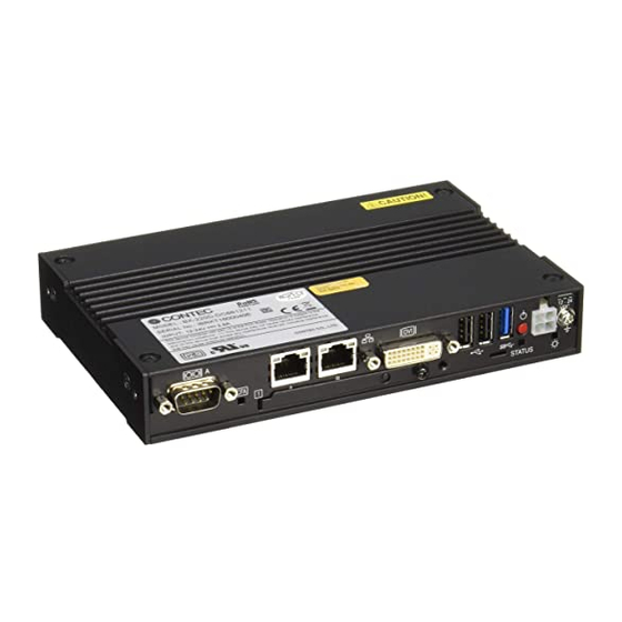
5. Each Component Function 5. Each Component Function Component Name Front View BX-220D-DC7xxxxx POWER SWITCH USB 3.0 SERIAL A LAN A LAN B DVI-I USB 2.0 DC-IN 12 - 24 C F A STATUS ACCESS LED STATUS LED POWER LED CFast1 Figure 5.1. -
Page 63: System Configuration
5. Each Component Function Table 5.1. Component Function Name Function POWER LED Power ON display LED STATUS LED Status LED ACCESS LED CFast disk access display LED DC-IN DC power input connector POWER-SW Power switch MIC IN Mike in (φ3.5 PHONE JACK) LINE OUT Line out (φ3.5 PHONE JACK) DVI-I... -
Page 64: Component Function
ON (Red) You can control the behavior of LED from the user application. *1 API that controls STATUS LED is available. For more information, visit the CONTEC's Web site. DC Power Input Connector: DC-IN To supply the power, always use the power supply listed below. -
Page 65: Power Sw
5. Each Component Function POWER SW POWER SW is provided. LINE OUT Interface : LINE OUT The product is equipped with a connector for line output. As such, headphones or an amplified speaker can be connected. MIC IN Interface : MIC The product is equipped with a connector for microphone input. -
Page 66: Dvi Interface: Dvi-I
DVI Interface: DVI-I A DVI-I interface is provided. A CRT display (or a 15-pin D-SUB CRT when the included DVI–Analog RGB conversion adapter is used) or a flat-panel display from CONTEC can be connected. The connector name is DVI (DVI-I 29 pin). - Page 67 5. Each Component Function Table5.5 DVI–analog RGB conversion adapter DVI-I 29 pin Connector type 15.00 6.20 30.00 5.80 [mm] Analog RGB signals Pin No. Signal name Pin No. Signal name GREEN BLUE N.C. N.C. DDC DATA HSYNC VSYNC DDC CLK CAUTION If the OS is booted without connecting the display cable to the DVI interface, and then the display is connected after the OS boots, the display may not be shown properly.
-
Page 68: Display Port Interface : Display Port
5. Each Component Function Display Port Interface : Display Port A Display Port interface is provided. As such, a display equipped with a Display Port can be connected. Table 5.6 Display Port Connector Display Port 20 pin Connector type Pin No. Signal name Pin No. -
Page 69: Usb3.0 Port : Usb3.0
5. Each Component Function USB3.0 Port : USB3.0 This product is equipped with 1 channel for USB 3.0 TYPE-A interface. Table 5.7 USB3.0 Connector Signal name Pin No. USB3.0 USB_VCC DATA- DATA+ USB_GND SSRX- SSRX+ USB_GND SSTX- SSTX+ USB2.0 Port : USB2.0 This product is equipped with 2 channel for USB 2.0 TYPE-A interface. -
Page 70: Giga Bit-Ethernet: Lan A, B
5. Each Component Function Giga bit-Ethernet: LAN A, B This product is equipped with 2 ports for giga bit. Network type : 1000BASE-T/100BASE-TX/10BASE-T Transmission speed : 1000M/100M/10M bps Max. network path length : 100m/segment Controller : Intel I210IT controller Use a category 5e cable for 1000 Mbps operation. Table 5.9. -
Page 71: Cfast Card Connector : Cfast1, 2
5. Each Component Function CFast Card Connector : CFast1, 2 The CF Card (Type I : dedicated to the memory card) can be connected. Table 5.10 CFast Card Connector Connector type CFast Card Connector Pin No. Signal name Pin No. Signal name N.C. -
Page 72: Serial Port Interface: Serial A, B
2F8h - 2FFh IRQ 3 RS-485*3 3E8h – 3EFh*4 IRQ7 *4 *3 API is required to use RS-485. For more information, visit the CONTEC's Web site. *4 Leave these settings as configured. Table 5.12. Serial Port Connector 9-pin D-SUB (MALE) Connector type No.4-40UNC... -
Page 73: Ras Functions
A RAS port is provided for this product. This port offers watchdog timer, remote reset, and general-purpose I/O RAS functions. API is required to use RAS. For more information, visit the CONTEC's Web site. Table 5.13. RAS Connector Connector type 15 pin D-SUB (FEMALE) No.4-40UNC... - Page 74 5. Each Component Function Connection methods Figure 5.4. Half-Duplex Connection Method Figure 5.5. Full-Duplex Connection Method BX-220 User’s manual...
-
Page 75: General Purpose Input/Output And Remote Power On/Reset
5. Each Component Function General Purpose Input/Output and Remote Power On/Reset This product is equipped with three general purpose insulation-type inputs and outputs. Inputs can be used as remote power on and remote reset inputs. It is necessary to configure BIOS settings to use an input signal as a remote power on or remote reset signal. - Page 76 5. Each Component Function External I/O Circuit (External circuit) (PCOM) 4.7kΩ 1/4W PS2811-1 External power (12 - 24VDC) (IN) 510Ω 1kΩ Input (PI 0 - 2) contacts RAS Connector Figure 5.6. Input circuit (External circuit) (PO 0 - 2) 2.7kΩ External power PS2811-1 (Max.
- Page 77 5. Each Component Function BX-220 User’s manual...
-
Page 78: Appendix
6. Appendix 6. Appendix POST Codes Table 6.1. POST Codes < 1 / 3 > POST Description (hex) < Security (SEC) phase > Power ON. The detection of the reset kind (Hard/Soft) Initialize the microcode load previous AP Initialize the microcode load previous North Bridge Initialize the microcode load previous South Bridge Initialize the microcode load previous OEM Microcode load... - Page 79 6. Appendix Table 6.1 POST Codes < 2 / 3 > POST Description (hex) CPU DXE installation start 64h - 67h CPU DXE installation start (Specific CPU module) PCI host bridge installation North Bridge DXE initialization starts North Bridge DXE SMM initialization starts 6Bh - 6Fh North Bridge DXE initialization (Specific North Bridge module) South Bridge DXE initialization starts...
- Page 80 6. Appendix Table 6.1 POST code < 3 / 3 > POST Description (hex) USB hotplug PCI bus hot plug NVRAM cleanup Configuration reset (Reset the NVRAM settings) B8h - BFh For future AMI codes reserved C0h - CFh OEM BDS initialization code ACPI/ASL Checkpoints S1 sleep system during migration.
-
Page 81: Serial I/O Address And Register Function
6. Appendix SERIAL I/O Address and Register Function The following table lists the I/O addresses in case of SERIAL A. Table 6.2. I/O Port Addresses I/O address DLAB Read/Write Register 03F8H Transmitter holding register Receive buffer register Divisor latch register (LSB) 03F9H Divisor latch register (MSB) Interrupt enable register... - Page 82 6. Appendix Table 6.3. Function of Each Register < 1 / 4 > I/O address Description 03F8H THR: Transmitter Holding Register [DLAB=0] bit7 bit0 Register dedicated to write transmitted data to 03F8H RBR: Reciever Buffer Register [DLAB=O] bit0 bit7 Register dedicated to read received data from 03F8H DLL: Divisor Latch (LSB) [DLAB=1] bit0...
- Page 83 6. Appendix Table 6.3. Function of Each Register < 2 / 4 > I/O address Description 03FAH IIR : Interrupt Identification Register Interrupt details 1: Do not generate interrupts 0: Generate interrupts bit2 bit1 bit0 Priority Description Interrupts are not generated. Generated by overrun, parity, framing error or break 1 (high) interrupt.
- Page 84 6. Appendix Table 6.3. Function of Each Register < 3 / 4 > I/O address Description 03FCH MCR: Modem Control Register Loop IRQ RTS DTR 0 : Inactive [HIGH] 1 : Active [LOW] RTS 0 : Inactive [HIGH] 1 : Active [LOW] Interrupt control bit 0 : Disable...
- Page 85 6. Appendix Table 6.3. Function of Each Register < 4 / 4 > I/O address Description 03FEH MSR : Modem Status Register DSR CTS DDCD TERI DDSR DCTS Delta CTS Delta DSR Trailing edge RI Delta data carrier detect 03FFH SCR : Scratchpad Register This is an 8-bit, readable/writable register which is available to the user to allow data to be saved temporarily.
- Page 86 6. Appendix Baud Rate Settings A baud rate is set by software by dividing the clock input (1.8432MHz). The baud rate in terms of hardware can be set to a maximum of 115,200 bps for SERIALA, B. The baud rates available in practice depend on the operating environment (cable, software, etc.).
-
Page 87: Watch-Dog-Timer
6. Appendix Watch-Dog-Timer The watchdog timer serves as a safeguard against possible system lock-up in your industrial computer system. In most industrial environments, there are heavy equipment, generators, high-voltage power lines, or power drops that have adverse effects on your computer system. For instance, when a power drop occurs, it could cause the CPU to come to a halt state or enter into an infinite loop, resulting in a system lock-up. - Page 88 6. Appendix ;------------------------------------------- MOV DX,2EH MOV AL,87H OUT DX,AL OUT DX,AL ;----------------------------------------------- ; Select logical device WDT(number 8) ;----------------------------------------------- MOV DX,2EH MOV AL,07H OUT DX,AL MOV DX,2FH MOV AL,08H OUT DX,AL ;--------------------------------------------------- ;Activate logical device WDT(number 8) ;--------------------------------------------------- MOV DX,2EH MOV AL,30H OUT DX,AL MOV DX,2FH...
- Page 89 6. Appendix MOV DX,2EH MOV AL,07H OUT DX,AL MOV DX,2FH MOV AL,08H OUT DX,AL ;-------------------------------------------------- ;Set time of WDT and start to count down ;-------------------------------------------------- MOV DX,2EH MOV AL,F1H OUT DX,AL MOV DX,2FH ;---------------------------------------------------------------------------------- ;The data of an example is 15 seconds.(01H=1sec.- FFH=255sec.) MOV AL,0FH ;...
- Page 90 6. Appendix ;----------------------------------- ;The data of 00H is stop WDT MOV AL,00H ;----------------------------------- OUT DX,AL ;----------------------------------- ;Exit the extended function mode ;----------------------------------- MOV DX,2EH MOV AL,AAH OUT DX,AL CAUTION The timer’s intervals have a tolerance of ±2 seconds. BX-220 User’s manual...
-
Page 91: Battery
6. Appendix Battery Battery Specification This product uses the following battery. - Type : Lithium primary battery - Model : BR-1/2AA - Maker : Panasonic - Nominal voltage : 3V - Nominal capacity : 1000mAh - Lithium content : 1g or less Removing the battery Remove the battery according to the following figure. -
Page 92: List Of Options
7. List of Options List of Options AC adapter ACAP19-01 AC adapter (Input: 100-240VAC, Output: 19VDC 3.42A) CFast Card(SLC) CFast-4GB-A 4GB CFast Card CFast-8GB-A 8GB CFast Card CFast-16GB-A 16GB CFast Card CFast Card(MLC) CFS-32GBM-A 32GB CFast Card Terminal block for connecting the RAS connector IPC-PSD-20 Terminal block for connecting the RAS connector CAUTION... - Page 93 //www.contec.co.jp/ English http: //www.contec.com/ Chinese http: //www.contec.com.cn/ No part of this document may be copied or reproduced in any form by any means without prior written consent of CONTEC CO., LTD. [02202015] [03052015] Management No. NA03679 [03052015_rev1] Parts No.
Need help?
Do you have a question about the BX220 Series and is the answer not in the manual?
Questions and answers