
Related Manuals for AEMC CA7027


Summary of Contents for AEMC CA7027
- Page 1 CA7027 FAULT MAPPER PRO ® GRAPHICAL TDR E N G L I S H User Manual GlobalTestSupply www. .com uality Products Online at: sales@GlobalTestSupp...
- Page 2 Statement of Compliance Chauvin Arnoux , Inc. d.b.a. AEMC Instruments ® ® certifies that this instrument has been calibrated using standards and instruments traceable to international standards. We guarantee that at the time of shipping your instrument has met its published specifications.
-
Page 3: Table Of Contents
Table of Contents 1. INTRODUCTION ................2 1.1 International Electrical Symbols ..........2 1.2 Receiving Your Shipment ............3 1.3 Ordering Information ..............3 1.3.1 Accessories and Replacement Parts ......3 2. PRODUCT FEATURES ..............4 2.1 Description ................4 2.2 Key Features: ................4 2.3 Fault Mapper Pro Features .............5 ®... -
Page 4: Introduction
CHAPTER 1 INTRODUCTION Warning ● This instrument meets the safety requirements of IEC61010- 1:1995. ● The Model CA7027 is designed for use on de-energized circuits only. ● Connection to line voltages will damage the instrument and could be hazardous to the operator. ● This instrument is protected against connection to telecom network voltages according to EN61326-1. ● Safety is the responsibility of the operator. -
Page 5: Receiving Your Shipment
Save the damaged packing container to substantiate your claim. Ordering Information Fault Mapper Pro Model CA7027 ........Cat. #2127.84 ® Includes carrying case, 4mm color-coded banana plugs with alligator clips, 4 x1.5V AA batteries, user manual and product warranty card. -
Page 6: Product Features
Measures cable length and indicates distance to faults to a range of 19,000 ft (6000m) Graphical LCD Easy identification of short range faults Emits an audible tone, used to trace and identify the type of fault Fault Mapper Pro Model CA7027 ® GlobalTestSupply www. .com uality Products Online at: sales@GlobalTestSupp... -
Page 7: Fault Mapper Pro ® Features
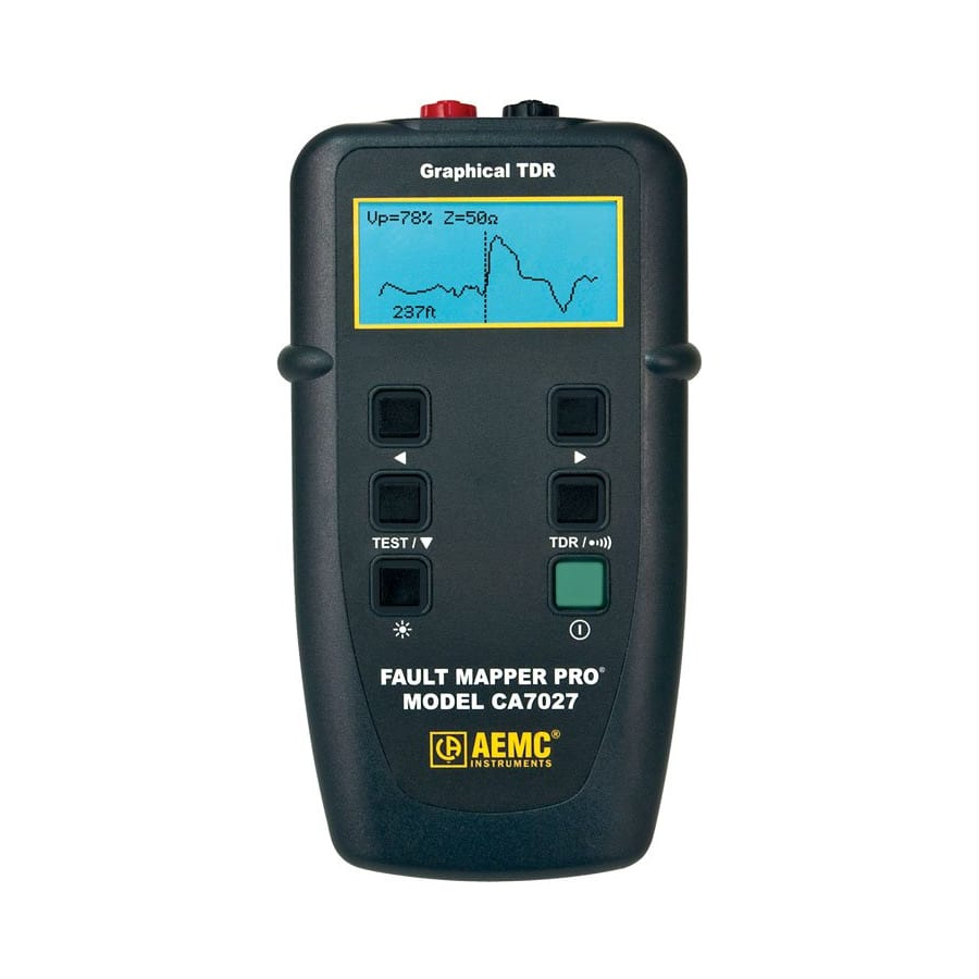
AEMC Instruments Fault Mapper Pro VX.X TEST / TDR / FAULT MAPPER PRO MODEL CA7027 1. Banana plug input (Red/Black) 2. Graphical LCD 3. Cable select and Vp (Velocity of Propagation) decrement button 4. Test /function select button 5. Backlight button 6. -
Page 8: Specifications
(Vp) along the cable length. Accurate positioning of the cursor is also required. **Specifications are subject to change without notice. Fault Mapper Pro Model CA7027 ® GlobalTestSupply www. -
Page 9: Accuracy
Accuracy The CA7027 is able to measure distances to faults and cable lengths to an accuracy of ±1%. This measurement accuracy is based on the correct value of Vp being used for the cable under test, and homogeneity of the Vp along the cable length. -
Page 10: Operation
When locating faults with the Fault Mapper Pro the cursor should be positioned at the beginning of the feature on ® the cable waveform as shown below. Vp=72% Z=100Ω 621ft Fault Mapper Pro Model CA7027 ® GlobalTestSupply www. .com uality Products Online at: sales@GlobalTestSupp... -
Page 11: Getting Started
5. Press the button again to save changes and exit set-up mode. TDR / NOTE: When the Fault Mapper Pro is turned off, it will retain the ® current set-up parameters. Fault Mapper Pro Model CA7027 ® GlobalTestSupply www. .com uality Products Online at: sales@GlobalTestSupp... -
Page 12: Backlight
Tone Generator The Fault Mapper Pro may also be used as a tone generator, to trace ® and identify cables and wires. The user will need a cable tone tracer, such as the AEMC Tone Receiver/Cable Tracer Model TR03 (Cat. #2127.76) or equivalent. Pressing the button will inject a warbling (oscillating) tone into the TDR / cable or link under test. When set, the following will be displayed: * * * * * * * * * * * * * * * * * * *... -
Page 13: Selecting Full Scale Sensitivity
1. Take a cable sample of exact length increments (ft or m) longer than 300 ft (100m). 2. Measure the exact length of the cable using a tape measure. Fault Mapper Pro Model CA7027 ® GlobalTestSupply www. .com... -
Page 14: Attaching A Cable To The Fault Mapper Pro
Black clip to the shield. Twisted Pair: Separate out one pair and connect the red and black clips to the two wires of the pair. Multi-conductor Cable: Connect the clips to any two wires. Coaxial Cable Shielded Cable Twisted Pair Multi-conductor Cable Fault Mapper Pro Model CA7027 ® GlobalTestSupply www. .com uality Products Online at: sales@GlobalTestSupp... -
Page 15: Testing A Cable
To determine the distance to an event, position the cursor at the beginning of the event and read off the distance as shown below. Vp=72% Z=100Ω 413ft On the fault curve shown in the previous two screens, a low impedance event occurs at 210 ft, shown by a downward spike on the curve, and a high impedance event occurs at 413 ft. The open end of the cable is shown as a large positive spike This is used to determine the end (length) of the cable. Fault Mapper Pro Model CA7027 ® GlobalTestSupply www. .com uality Products Online at: sales@GlobalTestSupp... -
Page 16: Single Shot And Continuous Scanning Modes
6.7 pulses per second. In this mode the Fault Mapper Pro is able to more easily identify ® intermittent cable faults. 4.13 Typical Fault Displays The following table shows typical fault traces to assist you in the identifica- tion of faults using the CA7027: Type Type Cat5 STP T/Pair Jelly PE Cat5 UTP T/Pair PE... -
Page 17: Maintenance
CHAPTER 5 MAINTENANCE Use only factory specified replacement parts. AEMC will not be held ® responsible for any accident, incident, or malfunction following a repair done other than by its service center or by an approved repair center. Changing the Battery Disconnect the instrument from any cable or network link. - Page 18 GlobalTestSupply www. .com uality Products Online at: sales@GlobalTestSupp...
-
Page 19: Limited Warranty
AEMC Instruments, not by the distributor from whom it was ® purchased. This warranty is void if the unit has been tampered with, abused or if the defect is related to service not performed by AEMC Instruments. ® For full and detailed warranty coverage, please read the Warranty Coverage Information, which is attached to the Warranty Registration Card (if enclosed) or is available at www.aemc.com. - Page 20 01/12 99-MAN 100361 v2 Chauvin Arnoux , Inc. d.b.a. AEMC Instruments ® ® GlobalTestSupply www. .com uality Products Online at: sales@GlobalTestSupp...
Need help?
Do you have a question about the CA7027 and is the answer not in the manual?
Questions and answers