
Related Manuals for EWM Tetrix 350


Summary of Contents for EWM Tetrix 350
- Page 1 Operating instructions Welding machine Tetrix 350 AC/DC Synergic Plasma 099-004854-EW501 19.02.2014 Register now! For your benefit Jetzt Registrieren und Profitieren! www.ewm-group.com...
-
Page 2: General Instructions
© EWM HIGHTEC WELDING GmbH · Dr. Günter-Henle-Str. 8 · D-56271 Mündersbach, Germany The copyright to this document remains the property of the manufacturer. -
Page 3: Table Of Contents
Contents Notes on the use of these operating instructions Contents 1 Contents ..............................3 2 Safety instructions ..........................8 Notes on the use of these operating instructions ................8 Explanation of icons ........................9 General ............................10 Transport and installation ......................14 2.4.1 Ambient conditions ....................... - Page 4 Contents Notes on the use of these operating instructions TIG welding ..........................40 5.8.1 Welding torch and workpiece line connection .............. 40 5.8.2 Shielding gas supply (shielding gas cylinder for welding machine)......41 5.8.2.1 Connecting the shielding gas supply ............. 42 5.8.2.2 Setting the shielding gas quantity ..............
- Page 5 Contents Notes on the use of these operating instructions 5.11 Welding programs ........................74 5.11.1 Selection and adjustment ..................... 75 5.11.2 Specifying max. no. of accessible programs ..............75 5.11.3 Example "Program with synergetic setting" ..............76 5.11.4 Example "Program with conventional setting" .............. 76 5.11.5 Accessories for switching over programs ..............
- Page 6 7.5.1 Interface for automated welding ................. 106 Vent coolant circuit ........................107 8 Technical data ............................. 108 Tetrix 350 AC/DC Plasma ......................108 9 Accessories ............................109 Welding torch cooling system ....................109 Transport systems ........................109 General accessories ........................109 Remote controls and accessories ....................
- Page 7 Contents Notes on the use of these operating instructions 099-004854-EW501 19.02.2014...
-
Page 8: Safety Instructions
Safety instructions Notes on the use of these operating instructions Safety instructions Notes on the use of these operating instructions DANGER Working or operating procedures which must be closely observed to prevent imminent serious and even fatal injuries. • Safety notes include the "DANGER" keyword in the heading with a general warning symbol. •... -
Page 9: Explanation Of Icons
Safety instructions Explanation of icons Explanation of icons Symbol Description Press Do not press Turn Switch Switch off machine Switch on machine ENTER ENTER (enter the menu) ENTER NAVIGATION NAVIGATION (Navigating in the menu) EXIT EXIT (Exit the menu) Time display (example: wait 4s/press) Interruption in the menu display (other setting options possible) Tool not required/do not use Tool required/use... -
Page 10: General
Safety instructions General General DANGER Electromagnetic fields! The power source may cause electrical or electromagnetic fields to be produced which could affect the correct functioning of electronic equipment such as IT or CNC devices, telecommunication lines, power cables, signal lines and pacemakers. •... - Page 11 Safety instructions General WARNING Smoke and gases! Smoke and gases can lead to breathing difficulties and poisoning. In addition, solvent vapour (chlorinated hydrocarbon) may be converted into poisonous phosgene due to the ultraviolet radiation of the arc! • Ensure that there is sufficient fresh air! •...
- Page 12 Safety instructions General CAUTION Obligations of the operator! The respective national directives and laws must be observed for operation of the machine! • National implementation of the framework directive (89/391/EWG), as well as the associated individual directives. • In particular, directive (89/655/EWG), on the minimum regulations for safety and health protection when staff members use equipment during work.
- Page 13 Safety instructions General CAUTION EMC Machine Classification In accordance with IEC 60974-10, welding machines are grouped in two electromagnetic compatibility classes (see technical data): Class A machines are not intended for use in residential areas where the power supply comes from the low-voltage public mains network.
-
Page 14: Transport And Installation
Safety instructions Transport and installation Transport and installation WARNING Incorrect handling of shielding gas cylinders! Incorrect handling of shielding gas cylinders can result in serious and even fatal injury. • Observe the instructions from the gas manufacturer and in any relevant regulations concerning the use of compressed air! •... -
Page 15: Ambient Conditions
Safety instructions Transport and installation 2.4.1 Ambient conditions CAUTION Installation site! The machine must not be operated in the open air and must only be set up and operated on a suitable, stable and level base! • The operator must ensure that the ground is non-slip and level, and provide sufficient lighting for the place of work. -
Page 16: Intended Use
3.1.2.1 TIG activArc welding The EWM activArc process, thanks to the highly dynamic controller system, ensures that the power supplied is kept virtually constant in the event of changes in the distance between the welding torch and the weld pool, e.g. during manual welding. Voltage losses as a result of a shortening of the distance between the torch and molten pool are compensated by a current rise (ampere per volt - A/V), and vice versa. -
Page 17: Documents Which Also Apply
Intended use Documents which also apply Documents which also apply 3.2.1 Warranty NOTE For further information, please see the accompanying supplementary sheets "Machine and Company Data, Maintenance and Testing, Warranty"! 3.2.2 Declaration of Conformity The designated machine conforms to EC Directives and standards in terms of its design and construction: •... -
Page 18: Machine Description
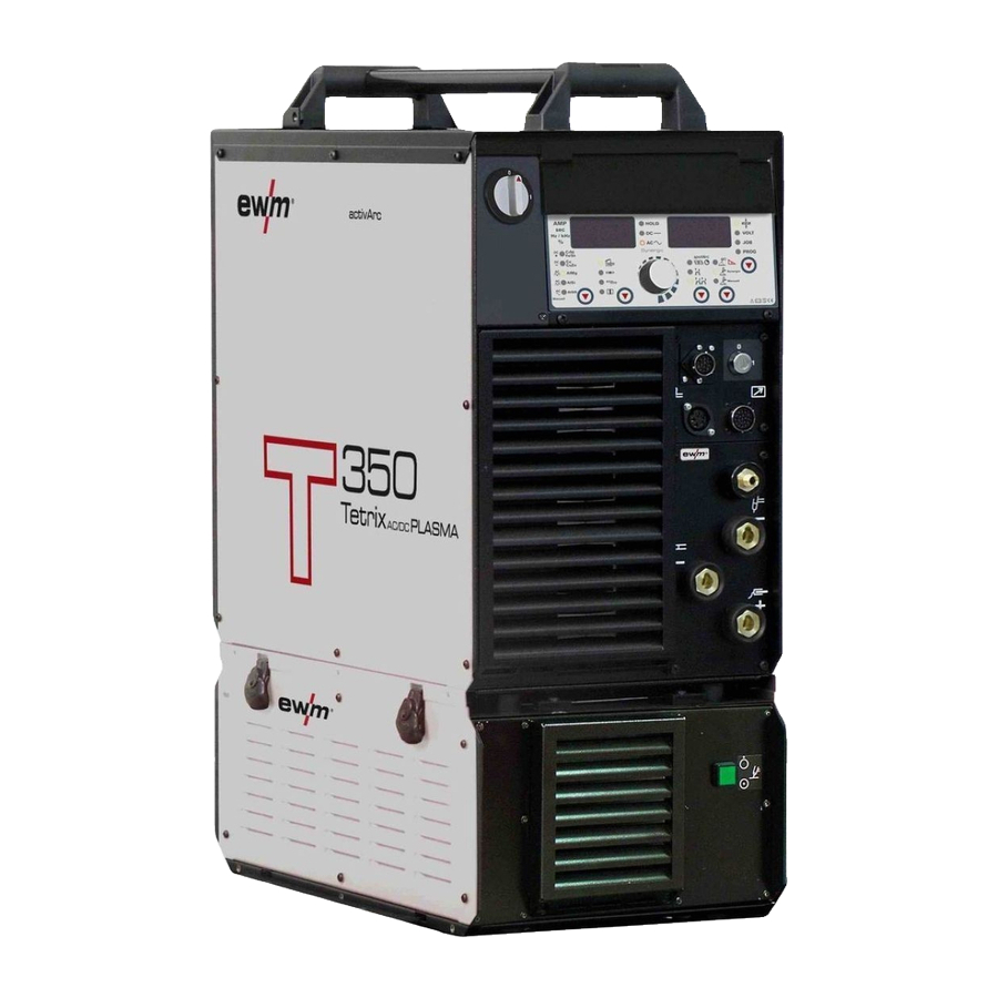
Machine description Front view Machine description NOTE The maximum possible machine configuration is given in the text description. If necessary, the optional connection may need to be retrofitted (see "Accessories" chapter). Front view Figure 4-1 099-004854-EW501 19.02.2014... - Page 19 Machine description Front view Item Symbol Description Carrying handle Machine control See Machine control – operating elements chapter Cooling air inlet Machine feet Pilot arc button with signal light Signal light off: pilot arc off Signal light on: pilot arc lit Connection socket, welding current “+”...
-
Page 20: Rear View
Machine description Rear view Rear view Figure 4-2 099-004854-EW501 19.02.2014... - Page 21 Machine description Rear view Item Symbol Description 19-pole connection socket Analogue interface for mechanised welding 7-pole connection socket (digital) For connecting digital accessory components (documentation interface, robot interface or remote control, etc.). PC interface, serial (D-Sub connection socket, 9-pole) G1/4" connecting nipple, plasma gas connection Connection to the pressure reducer G1/4"...
-
Page 22: Machine Control - Operating Elements
Machine description Machine control – Operating elements Machine control – Operating elements Figure 4-3 Item Symbol Description Polarity changeover (TIG manual) button Select material type (TIG Synergic) key button DC welding with positive polarity on the Chrome/nickel alloys / iron / electrode holder in relation to the steel alloys workpiece (pole reversing switch, MMA... - Page 23 Machine description Machine control – Operating elements Item Symbol Description Select seam type button Fillet weld Butt joint Fillet weld - lap joint Vertical-down Operating mode button spotArc / Spotmatic (spot time setting range) Non-latched Latched TIG pulse welding TIG automated pulses (frequency and balance) TIG pulses with times, green light / Fast TIG DC pulses with frequency and balance, red light TIG AC special...
-
Page 24: Function Sequence
Machine description Machine control – Operating elements 4.3.1 Function sequence Figure 4-4 Item Symbol Description Select welding parameters button This button is used to select the welding parameters depending on the welding process and operating mode used. Gas pre-flow time (TIG) absolute setting range 0.0 sec to 20.0 sec (0.1s increments). - Page 25 Machine description Machine control – Operating elements Item Symbol Description Down-slope time (TIG) 0.00 s to 20.0 s (0.1 s increments). The down-slope time can be set separately for non-latched and latched. AMP% End-crater current (TIG) Setting range 1 % to 200 % (1 % increments). Percentage of the main current. Gas post-flow time (TIG) Setting ranges: 0.00 sec to 40.0 sec (0.1 sec increments).
-
Page 26: Design And Function
Design and function General Design and function General WARNING Risk of injury from electric shock! Contact with live parts, e.g. welding current sockets, is potentially fatal! • Follow safety instructions on the opening pages of the operating instructions. • Commissioning may only be carried out by persons who have the relevant expertise of working with arc welding machines! •... -
Page 27: Installation
Design and function Installation Installation WARNING Risk of accident due to improper transport of machines that may not be lifted! Do not lift or suspend the machine! The machine can fall down and cause injuries! The handles and brackets are suitable for transport by hand only! •... -
Page 28: Mains Connection
Design and function Mains connection Mains connection DANGER Hazard caused by improper mains connection! An improper mains connection can cause injuries or damage property! • Only use machine with a plug socket that has a correctly fitted protective conductor. • If a mains plug must be fitted, this may only be carried out by an electrician in accordance with the relevant national provisions or regulations! •... -
Page 29: Welding Torch Cooling System
Design and function Welding torch cooling system Welding torch cooling system CAUTION Use of unsuitable coolants results in damage to the welding torch! Unsuitable coolants can cause damage to the welding torch! • Use only KF 23E coolants (observe temperature range of - 10 °C bis + 40°C). NOTE Observe the fitting and connection instructions given in the relevant operating instructions for the cooling unit. -
Page 30: Plasma Welding
Design and function Plasma welding Plasma welding 5.7.1 Welding torch connection (with gas metering unit GMU) NOTE If the plasma and shielding gases are connected via a gas metering unit (GMU), the connection between the welding machine and the GMU is created using the supplied gas connection lines with G 1/4"... - Page 31 Design and function Plasma welding Item Symbol Description G1/4 gas connection line Connection of the welding gases between the gas metering unit (GMU) and welding machine G1/4" shielding gas connecting nipple, welding machine output Connection to the welding torch or gas metering unit (GMU) G1/4 shielding gas connecting nipple, gas metering unit input Connection to the welding machine G1/4"...
-
Page 32: Welding Torch Connection (No Gas Metering Unit Gmu)
Design and function Plasma welding 5.7.2 Welding torch connection (no gas metering unit GMU) NOTE Before commissioning, the plasma welding torch must be equipped for the welding JOB and correspondingly set/adjusted! Figure 5-4 Item Symbol Description Connection socket, "-" welding current TIG/Plasma welding current connection Pilot current connection socket Plasma welding torch nozzle potential... -
Page 33: Connection For Workpiece Lead
Design and function Plasma welding 5.7.3 Connection for workpiece lead • Insert the cable plug on the work piece lead into the "+" welding current connection socket and lock by turning to the right. 5.7.4 Shielding and plasma gas supply WARNING Incorrect handling of shielding gas cylinders! Incorrect handling of shielding gas cylinders can result in serious and even fatal injury. -
Page 34: Connecting The Shielding Gas Supply
Design and function Plasma welding 5.7.4.1 Connecting the shielding gas supply Figure 5-5 Item Symbol Description Pressure regulator Shielding gas cylinder Output side of the pressure regulator Cylinder valve • Place the shielding gas cylinder into the relevant cylinder bracket. •... - Page 35 Design and function Plasma welding Figure 5-6 Item Symbol Description G1/4" connecting nipple, plasma gas connection Connection to the pressure reducer G1/4" connecting nipple, shielding gas connection Connection to the pressure reducer • Screw the connection coupling of the plasma gas line onto the G1/4" connecting nipple, plasma gas connection.
-
Page 36: Setting The Shielding Gas Quantity
Design and function Plasma welding 5.7.4.2 Setting the shielding gas quantity NOTE Rule of thumb for the gas flow rate: Diameter of gas nozzle in mm corresponds to gas flow in l/min. Example: 7mm gas nozzle corresponds to 7l/min gas flow. Incorrect shielding gas setting! If the shielding gas setting is too low or too high, this can introduce air to the weld pool and may cause pores to form. -
Page 37: Select Welding Task
Design and function Plasma welding 5.7.5 Select welding task NOTE As the plasma welding process is based directly on the TIG welding process, the TIG descriptions are used for plasma welding, with just a few differences. All settings required for a specific welding task are factory-set in the machine control and stored under a JOB number. -
Page 38: Welding Data Display
Design and function Plasma welding 5.7.7 Welding data display The following welding parameters can be displayed before (nominal values), during (actual values) or after welding (hold values): “Left-hand display” Parameter Before welding During welding After welding (nominal values) (actual values) (hold values) ... -
Page 39: Arc Ignition
Design and function Plasma welding 5.7.8 Arc ignition The pilot arc is activated/deactivated by pressing the "Pilot arc on/off" push-button. After activating the pilot arc, the pre-set gas pre-flow time runs, the pilot arc current ignites without workpiece contact between the electrode and nozzle, and the control lamp in the push-button illuminates. CAUTION Oxidation of the tungsten electrode! To protect the tungsten electrode against oxidation carry out the following actions... -
Page 40: Tig Welding
Design and function TIG welding TIG welding 5.8.1 Welding torch and workpiece line connection CAUTION Equipment damage due to improperly connected coolant lines! If the coolant lines are not connected or a gas-cooled welding torch is used, the coolant circuit is interrupted and equipment damage can occur. •... -
Page 41: Shielding Gas Supply (Shielding Gas Cylinder For Welding Machine)
Design and function TIG welding • Insert the plug on the welding current lead into the "-" welding current connection socket and lock. • Insert the torch control lead plug into the “5-pole connection socket, welding torch control lead” and lock. -
Page 42: Connecting The Shielding Gas Supply
Design and function TIG welding 5.8.2.1 Connecting the shielding gas supply Figure 5-8 Item Symbol Description Pressure regulator Shielding gas cylinder Output side of the pressure regulator Cylinder valve • Place the shielding gas cylinder into the relevant cylinder bracket. •... -
Page 43: Setting The Shielding Gas Quantity
Design and function TIG welding 5.8.2.2 Setting the shielding gas quantity NOTE Rule of thumb for the gas flow rate: Diameter of gas nozzle in mm corresponds to gas flow in l/min. Example: 7mm gas nozzle corresponds to 7l/min gas flow. Incorrect shielding gas setting! If the shielding gas setting is too low or too high, this can introduce air to the weld pool and may cause pores to form. -
Page 44: Tig Synergic Operating Principle
Design and function TIG Synergic operating principle TIG Synergic operating principle Figure 5-9 The machine is operated according to the TIG Synergic operating principle: In a similar way to the MIG machines with Synergic operation, three basic parameters – • Tungsten electrode diameter (A), •... -
Page 45: Synergic Parameter Setting In The Functional Sequence
Design and function TIG Synergic operating principle 5.9.1 Synergic parameter setting in the functional sequence When setting the welding current, all the necessary welding parameters are adjusted automatically during the functional sequence (see chap. “TIG functional sequences”) with the exception of the gas pre-flow time. -
Page 46: Set The Operating Principle (Conventional/Synergic)
Design and function TIG Synergic operating principle 5.9.3 Set the operating principle (conventional/synergic) ENTER EXIT NAVIGATION Figure 5-12 Display Setting/selection Exit the menu Exit Machine configuration Settings for machine functions and parameter display Operating principle • on = synergic parameter setting (factory setting) •... -
Page 47: Select Welding Task
Design and function TIG Synergic operating principle 5.9.4 Select welding task The welding task is selected using the buttons on the machine control on the welding machine. Signal lights (LED) display the welding parameter selection. NOTE It is only possible to change the basic welding parameters if: •... -
Page 48: Welding Data Display
Design and function TIG Synergic operating principle 5.9.6 Welding data display The following welding parameters can be displayed before (nominal values), during (actual values) or after welding (hold values): “Left-hand display” Parameter Before welding During welding After welding (nominal values) (actual values) (hold values) ... -
Page 49: Arc Ignition
Design and function TIG Synergic operating principle 5.9.7 Arc ignition 5.9.7.1 HF ignition Figure 5-13 The arc is started without contact from high-voltage ignition pulses. a) Position the welding torch in welding position over the workpiece (distance between the electrode tip and workpiece should be approx. -
Page 50: Optimising The Ignition Characteristics For Pure Tungsten Electrodes
Design and function TIG Synergic operating principle 5.9.9 Optimising the ignition characteristics for pure tungsten electrodes This parameter can be used to improve the ignition characteristics of “pure tungsten electrodes”, for example. The parameter is a %-value (factory-set to 20) and is changed across all JOBs. Control element Action Result... -
Page 51: Function Sequences/Operating Modes
Design and function TIG Synergic operating principle 5.9.11 Function sequences/operating modes Figure 5-15 Item Symbol Description Select welding parameters button This button is used to select the welding parameters depending on the welding process and operating mode used. Welding parameter setting rotary transducer Setting of all parameters such as welding current, sheet metal thickness, gas pre-flow time, etc. -
Page 52: Non-Latched Mode
Design and function TIG Synergic operating principle 5.9.11.2 Non-latched mode Figure 5-16 1st cycle: • Press and hold torch trigger 1. • The gas pre-flow time elapses. • HF ignition pulses jump from the electrode to the workpiece, the arc ignites. •... -
Page 53: Latched Mode
Design and function TIG Synergic operating principle 5.9.11.3 Latched mode Figure 5-17 Step 1 • Press torch trigger 1, the gas pre-flow time elapses. • HF ignition pulses jump from the electrode to the workpiece, the arc ignites. • Welding current flows and immediately assumes the ignition current value set (search arc at minimum setting). -
Page 54: Tig Spotarc
Design and function TIG Synergic operating principle 5.9.11.4 TIG spotArc This process is suitable for tack welding or joint welding of metal sheets made from steel and CrNi alloys up to a thickness of approximately 2.5 mm. Metal sheets of different thicknesses can also be welded on top of one another. - Page 55 Design and function TIG Synergic operating principle Figure 5-18 As an example the process is shown with HF ignition. Arc ignition with lift arc is also possible, however (see chapter "Arc ignition"). Sequence: • Press and hold torch trigger 1. •...
-
Page 56: Spotmatic
Design and function TIG Synergic operating principle 5.9.11.5 Spotmatic NOTE This function must be enabled before use, see "Advanced settings" chapter. In contrast to the spotarc operating mode, the arc ignites not by pressing the torch trigger as is usual, but by shortly touching the tungsten electrode against the workpiece. - Page 57 Design and function TIG Synergic operating principle Figure 5-19 As an example the process is shown with HF ignition. Arc ignition with lift arc is also possible, however (see chapter "Arc ignition"). Select the process activation type (see chapter "Advanced settings"). Up- and down-slope times possible for long setting range of the spot time (0.01 s - 20.0 s) only.
-
Page 58: Non-Latched Operation, Version C
Design and function TIG Synergic operating principle 5.9.11.6 Non-latched operation, version C Figure 5-20 1st cycle • Press torch trigger 1, the gas pre-flow time elapses. • HF ignition pulses jump from the electrode to the workpiece, the arc ignites. •... -
Page 59: Pulses, Function Sequences
Design and function TIG Synergic operating principle 5.9.12 Pulses, function sequences NOTE The function sequences in pulses basically behave in the same way as in standard welding, but during the main current phase there is a continual switching back and forth between the pulse and pause currents at the relevant times. -
Page 60: Pulse Variants
Design and function TIG Synergic operating principle 5.9.13 Pulse variants NOTE The machines have an integrated pulse device. With pulses, the machine switches back and forth between the pulse current (main current) and pause current (secondary current). 5.9.13.1 Pulses (thermal pulses) With thermal pulses, the pulse and pause times (frequency up to 200 Hz) and the pulse edges (ts1 and ts2) are entered in seconds on the control. -
Page 61: Khz Pulses (Metallurgic Pulses)
Design and function TIG Synergic operating principle 5.9.13.2 KHz pulses (metallurgic pulses) The kHz pulses (metallurgic pulses) use the plasma pressure produced at high currents (arc pressure) which is used to achieve a constricted arc with concentrated heat feeding. The frequency can be infinitely adjusted from 50 Hz to 15 kHz and the pulse balance from 1-99 %. -
Page 62: Ac Pulses
Design and function TIG Synergic operating principle 5.9.13.4 AC pulses (AC pulse, max. 50Hz) Setting: = pulse current AMP% = pulse pause current / basic current tpuls = pulse time tpause = pulse pause time Figure 5-25 5.9.13.5 AC special Application: e.g. -
Page 63: Tig Activarc Welding
TIG Synergic operating principle 5.9.14 TIG activArc welding The EWM activArc process, thanks to the highly dynamic controller system, ensures that the power supplied is kept virtually constant in the event of changes in the distance between the welding torch and the weld pool, e.g. -
Page 64: Welding Torch (Operating Variants)
Design and function TIG Synergic operating principle 5.9.15 Welding torch (operating variants) Different torch versions can be used with this machine. Functions on the operating elements, such as torch triggers (TT), rockers or potentiometers, can be modified individually via torch modes. Explanation of symbols for operating elements: Symbol Description... -
Page 65: Torch Mode And Up/Down Speed Setting
Design and function TIG Synergic operating principle 5.9.16 Torch mode and up/down speed setting The user has the modes 1 to 6 and modes 11 to 16 available. Modes 11 to 16 include the same function options as 1 to 6, but without tapping function for the secondary current. The function options in the individual modes can be found in the tables for the corresponding torch types. -
Page 66: Standard Tig Torch (5-Pole)
Design and function TIG Synergic operating principle 5.9.16.1 Standard TIG torch (5-pole) Standard torch with one torch trigger: Diagram Operating Explanation of symbols elements BRT1 = Torch trigger 1 (welding current on/off; secondary current via tapping function) Functions mode Operating elements Welding current On/Off (factory-set) - Page 67 Design and function TIG Synergic operating principle Standard torch with one rocker (MG rocker, two torch triggers) Diagram Operating Explanation of symbols elements BRT 1 = torch trigger 1 BRT 2 = torch trigger 2 Functions mode Operating elements Welding current On/Off Secondary current (factory-set) Secondary current (tapping mode) / (latched mode)
-
Page 68: Setting The First Increment
Design and function TIG Synergic operating principle 5.9.17 Setting the first increment Figure 5-29 ENTER EXIT NAVIGATION Figure 5-30 Display Setting/selection Exit the menu Exit Torch configuration menu Set welding torch functions Setting the first increment Setting: 1 to 20 (factory setting 1) NOTE This function is only available when using up/down torches in modes 4 and 14! 099-004854-EW501... -
Page 69: Mma Welding
Design and function MMA welding 5.10 MMA welding CAUTION Risk of being crushed or burnt. When replacing spent or new stick electrodes • Switch off machine at the main switch • Wear appropriate safety gloves • Use insulated tongs to remove spent stick electrodes or to move welded workpieces and •... - Page 70 Design and function MMA welding Item Symbol Description Connection socket, welding current “-” (with DC- polarity) connection for Electrode holder Connection socket, welding current “+” (with DC- polarity) Connection for workpiece lead • Insert cable plug of the electrode holder into either the "+" or "-" welding current connection socket and lock by turning to the right.
-
Page 71: Selection And Adjustment
Design and function MMA welding 5.10.2 Selection and adjustment Operating Action Result element Select MMA welding process. The signal light comes on in green. Set welding current. 5.10.3 Welding current polarity reversal (polarity reversal) This function can be used to reverse the welding current polarity electronically. For example, when welding with different electrode types for which different polarities are stipulated by the manufacturer, the welding current polarity can be switched easily on the control. -
Page 72: Frequency And Balance Setting
Design and function MMA welding 5.10.4 Frequency and balance setting Operating Action Result Displays element Switch on welding current polarity "AC" (see chapter "Changeover of the welding current polarity") Select the welding parameter alternating current frequency. Press until signal light comes on. -
Page 73: Hotstart Time
Design and function MMA welding 5.10.5.2 Hotstart time Control element Action Result Displays Select hotstart time welding parameter: Press until the hotstart time signal light sec comes Set hotstart time. 5.10.6 Arcforce Shortly before the electrode threatens to stick, the arcforcing device sets an increased current designed to prevent the electrode sticking. -
Page 74: Welding Programs
Design and function Welding programs 5.11 Welding programs NOTE Changes made to the other welding parameters during the course of the program have the equivalent effect on all programs. The change to the welding parameters is saved immediately in the JOB. The welding machine has 16 programs, which you can change during welding. -
Page 75: Selection And Adjustment
Design and function Welding programs 5.11.1 Selection and adjustment Setting welding programs using the welding machine control Operating Action Result Display element Press button until signal light PROG comes on. Welding current (left) and program no. (right) Select or retrieve program no., e.g. no. 1 Set operating mode (can be specified separately for each No change program). -
Page 76: Example "Program With Synergetic Setting
Design and function Welding programs 5.11.3 Example "Program with synergetic setting" Figure 5-32 5.11.4 Example "Program with conventional setting" Figure 5-33 5.11.5 Accessories for switching over programs The user can change, retrieve and save programs using the following components. Programs Component Create and change Retrieve... -
Page 77: Organising Welding Tasks (Mode "Job Manager")
Design and function Organising welding tasks (Mode "JOB Manager") 5.12 Organising welding tasks (Mode "JOB Manager") NOTE After carrying out any of the actions described, the machine switches back to the default parameters such as current and voltage. To ensure that all the changes are active, the welding machine should only be switched off after 5 seconds have elapsed. -
Page 78: Creating A New Job In The Memory Or Copying A Job
Design and function Organising welding tasks (Mode "JOB Manager") 5.12.2 Creating a new JOB in the memory or copying a JOB Copying a pre-defined welding task from the fixed memory (JOBs 1 to 128) to the free memory (JOBs 129-256): NOTE It is normally possible to adjust all 256 JOBs individually. -
Page 79: Loading An Existing Job From The Free Memory
Design and function Organising welding tasks (Mode "JOB Manager") 5.12.3 Loading an existing JOB from the free memory Operating Action Result Display element Press until the “VOLT” Select JOB Manager mode signal light is on Select JOB Manager mode 2 sec. Select the required JOB number using the rotary transducer (e.g. -
Page 80: Resetting Jobs 1-128 To The Factory Setting (Reset All Jobs)
Design and function Organising welding tasks (Mode "JOB Manager") 5.12.5 Resetting JOBs 1-128 to the factory setting (Reset All JOBs) Operating Action Result Display element Press until the “VOLT” Select JOB Manager mode signal light is on Select JOB Manager mode 2 sec. -
Page 81: Specifying Max. No. Of Accessible Jobs
Design and function Organising welding tasks (Mode "JOB Manager") 5.12.7 Specifying max. no. of accessible JOBs This function can be used to specify the maximum number of JOBs which can be retrieved from the free memory. The factory setting is for 10 JOBs to be accessible on the welding machine, but this figure can be increased to up to 128 if required. -
Page 82: Remote Control
Design and function Remote control 5.13 Remote control NOTE Insert the remote control control cable into the 19-pole connection socket for remote control connection and lock. 5.13.1 Manual remote control RT1 19POL Functions • Infinitely adjustable welding current (0% to 100%) depending on the preselected main current on the welding machine. -
Page 83: Manual Remote Control Rt Pws 1 19Pol
Design and function Remote control 5.13.7 Manual remote control RT PWS 1 19POL Functions • Infinitely adjustable welding current (0% to 100%) depending on the preselected main current at the welding machine • Pole reversing switch, suitable for machines with PWS function 5.13.8 Foot-operated remote control RTF1 19POL Functions •... -
Page 84: Protecting Welding Parameters From Unauthorised Access
Design and function Protecting welding parameters from unauthorised access 5.14 Protecting welding parameters from unauthorised access NOTE These accessory components can be retrofitted as an option, see Accessories chapter. To protect against unauthorised or unintentional adjustment of the welding parameters on the machine, the control input can be locked with the aid of a key switch. -
Page 85: Simultaneous Welding On Both Sides, Synchronisation Types
Design and function Simultaneous welding on both sides, synchronisation types 5.16 Simultaneous welding on both sides, synchronisation types This function is important, if two power sources are used to simultaneously weld on both sides, as is sometimes required for welding thick aluminium materials in the PF position. This ensures that, with alternating currents, the positive and negative pole phases are present on both power sources simultaneously, thus avoiding the arcs negatively influencing each other. -
Page 86: Synchronisation Via Cable (Frequency 50Hz To 200Hz)
Design and function Simultaneous welding on both sides, synchronisation types 5.16.2 Synchronisation via cable (frequency 50Hz to 200Hz) HINWEIS This application describes synchronisation (master/slave operation) with two machines in the TETRIX series. The following components are required: • The synchronisation interface SYNINT X10 •... -
Page 87: Interfaces For Automation
Design and function Interfaces for automation 5.17 Interfaces for automation CAUTION Damage to the machine due to improper connection! Unsuitable control leads or incorrect connection of input and output signals can cause damage to the machine. • Only use shielded control leads! •... -
Page 88: Remote Control Connection Socket, 19-Pole
Design and function Interfaces for automation 5.17.2 Remote control connection socket, 19-pole Figure 5-37 Pos. Signal shape Designation Output Connection for cable screen (PE) Output Current flows signal I>0, galvanically isolated (max. +- 15V/100mA) Output Reference voltage for potentiometer 10V (max. 10mA) Input Control value specification for main current, 0-10V (0V = I , 10V =... -
Page 89: Advanced Settings
Design and function Advanced settings 5.18 Advanced settings 5.18.1 TIG non-latched operating mode, C version ENTER EXIT NAVIGATION Figure 5-38 Display Setting/selection Exit the menu Exit Machine configuration Settings for machine functions and parameter display Non-latched operation (C version) • on = on •... -
Page 90: Configuring The Tig Potentiometer Torch Connection
Design and function Advanced settings 5.18.2 Configuring the TIG potentiometer torch connection DANGER Risk of injury due to electrical voltage after switching off! Working on an open machine can lead to fatal injuries! Capacitors are loaded with electrical voltage during operation. Voltage remains present for up to four minutes after the mains plug is removed. -
Page 91: Welding Current Display (Ignition, Secondary, End And Hotstart Currents)
Design and function Advanced settings 5.18.3 Welding current display (ignition, secondary, end and hotstart currents) The welding currents for secondary current, ignition current and end current (expert menu) can be displayed as percentages (factory setting) or absolute values on the machine display. ENTER EXIT NAVIGATION... -
Page 92: Ramp Function Foot-Operated Remote Control Rtf 1
Design and function Advanced settings 5.18.4 Ramp function foot-operated remote control RTF 1 ENTER EXIT NAVIGATION Figure 5-41 Display Setting/selection Exit the menu Exit Machine configuration (part two) Settings for machine functions and parameter display Ramp function Remote control RTF 1 The ramp function can be switched on and off Switch on Switching on machine function... -
Page 93: Menus And Sub-Menus On The Machine Control
Design and function Menus and sub-menus on the machine control 5.19 Menus and sub-menus on the machine control 5.19.1 Direct menus (direct access to parameters) Functions, parameters and their values can be accessed directly, e.g. can be selected by pressing a button once. -
Page 94: Machine Configuration Menu
Design and function Menus and sub-menus on the machine control 5.19.3 Machine configuration menu NOTE ENTER (enter the menu) • Switch off machine at the main switch • Press and hold the "welding parameters" button and switch the machine on again at the same time. - Page 95 Design and function Menus and sub-menus on the machine control EXIT ENTER NAVIGATION Figure 5-43 099-004854-EW501 19.02.2014...
- Page 96 Design and function Menus and sub-menus on the machine control Display Setting/selection Exit the menu Exit Torch configuration menu Set welding torch functions Torch mode (factory setting 1) Up-/Down speed Increase value = rapid current change (factory setting 10) Reduce value = slow current change Setting the first increment Setting: 1 to 20 (factory setting 1)
- Page 97 Design and function Menus and sub-menus on the machine control spotMatic Variation of operation mode spotArc, ignition with workpiece contact • on = on • off = off (factory setting) Short spot time Setting of 5–-999 ms (1-ms steps) Setting process activation •...
- Page 98 Design and function Menus and sub-menus on the machine control Display Setting/selection Reset (reset to factory settings) • off = aus (factory setting) • CFG = Reset the values in the machine configuration menu • CPL = Complete reset of all values and settings The reset is performed when leaving the menu (EXIT).
-
Page 99: Maintenance, Care And Disposal
Maintenance, care and disposal General Maintenance, care and disposal DANGER Risk of injury from electric shock! Cleaning machines that are not disconnected from the mains can lead to serious injuries! • Disconnect the machine completely from the mains. • Remove the mains plug! •... -
Page 100: Maintenance Work
In addition to this, returns are also possible throughout Europe via EWM sales partners. Meeting the requirements of RoHS We, EWM AG Mündersbach, hereby confirm that all products supplied by us which are affected by the RoHS Directive, meet the requirements of the RoHS (Directive 2002/95/EC). -
Page 101: Rectifying Faults
Rectifying faults Checklist for rectifying faults Rectifying faults All products are subject to rigorous production checks and final checks. If, despite this, something fails to work at any time, please check the product using the following flowchart. If none of the fault rectification procedures described leads to the correct functioning of the product, please inform your authorised dealer. - Page 102 Rectifying faults Checklist for rectifying faults No arc ignition Incorrect ignition type setting. Set ignition type changeover switch to the HF ignition setting. Bad arc ignition Material inclusions in the tungsten electrode due to contact with filler material or workpiece ...
-
Page 103: Machine Faults (Error Messages)
Rectifying faults Machine faults (error messages) Machine faults (error messages) NOTE A welding machine error is indicated by the collective fault signal lamp (A1) lighting up and an error code (see table) being displayed in the machine control display. In the event of a machine error, the power unit shuts down. - Page 104 Rectifying faults Machine faults (error messages) Error message Possible cause Remedy Err 20 Coolant Check coolant level and refill if necessary • The flow quantity of the torch coolant Check coolant level in the reverse cooler • has fallen below the permissible Check coolant lines for leaks and kinks minimum ->...
-
Page 105: Resetting Welding Parameters To The Factory Settings
Rectifying faults Resetting welding parameters to the factory settings Resetting welding parameters to the factory settings NOTE All customised welding parameters that are stored will be replaced by the factory settings. ENTER EXIT NAVIGATION Figure 7-1 Display Setting/selection Exit the menu Exit Service menu Modifications to the service menu may only be carried out by authorised maintenance... -
Page 106: Display Machine Control Software Version
Rectifying faults Display machine control software version Display machine control software version NOTE The query of the software versions only serves to inform the authorised service staff! ENTER EXIT NAVIGATION Figure 7-2 Display Setting/selection Exit the menu Exit Service menu Modifications to the service menu may only be carried out by authorised maintenance staff! Software version query (example) -
Page 107: Vent Coolant Circuit
Rectifying faults Vent coolant circuit Vent coolant circuit NOTE Coolant tank and quick connect coupling of coolant supply and return are only fitted in machines with water cooling. To vent the cooling system always use the blue coolant connection, which is located as deep as possible inside the system (close to the coolant tank)! Figure 7-3 099-004854-EW501... -
Page 108: Technical Data
Technical data Tetrix 350 AC/DC Plasma Technical data NOTE Performance specifications and guarantee only in connection with original spare and replacement parts! Tetrix 350 AC/DC Plasma PLASMA Setting range for welding current 5 A to 350 A Setting range for welding voltage 25,2 V to 39.0 V... -
Page 109: Accessories
Accessories Welding torch cooling system Accessories NOTE Performance-dependent accessories like torches, workpiece leads, electrode holders or intermediate hose packages are available from your authorised dealer. Welding torch cooling system Type Designation Item no. cool71 U43 Cooling unit with centrif. pump and reinforced 090-008220-00502 cooling UKV4SET 4M... -
Page 110: Options
Optional retrofit kit for key switch 092-001828-00000 ON 19POL Tetrix 300/351 Optional 19-pole retrofit connection socket 092-001827-00000 Accessory components and analogue A interface ON FILTER TETRIX 350 Retrofit option, dirt filter for air inlet 092-002392-00000 AC/DC Simultaneous welding on both sides, synchronisation types 9.6.1... -
Page 111: Job-List
Appendix A JOB-List Appendix A 10.1 JOB-List Process Material Wire Seam position Reserved CrNi/ Fe/ St CrNi/ Fe/ St CrNi/ Fe/ St CrNi/ Fe/ St ... - Page 112 Appendix A JOB-List Process Material Wire Seam position Cu/CuZn Cu/CuZn >3.2 Cu/CuZn Cu/CuZn Cu/CuZn Cu/CuZn Cu/CuZn Cu/CuZn >3.2 ...
- Page 113 Appendix A JOB-List Process Material Wire Seam position AlSi AlSi AlSi AlSi AlSi AlSi >3.2 AlSi AlSi ...
- Page 114 Appendix A JOB-List Process Material Wire Seam position Al99 Al99 Al99 Al99 >3.2 Al99 Al99 Al99 ...
-
Page 115: Overview Of Ewm Branches
Appendix B Overview of EWM branches Appendix B 11.1 Overview of EWM branches 099-004854-EW501 19.02.2014...
Need help?
Do you have a question about the Tetrix 350 and is the answer not in the manual?
Questions and answers