Ricoh PJ X5360N Field Service Manual
Hide thumbs
Also See for PJ X5360N:
- Specifications (4 pages) ,
- Quick setup manual (6 pages) ,
- Important information manual (56 pages)

Related Manuals for Ricoh PJ X5360N


Summary of Contents for Ricoh PJ X5360N
- Page 1 Model Rigel-PJ1 nx/nw Machine Codes: Y015/Y016 Field Service Manual 6 January, 2012...
-
Page 3: Important Safety Notices
Important Safety Notices • RISK OF ELECTRIC SHOCK DO NOT OPEN • TO REDUCE THE RISK OF ELECTRIC SHOCK, DO NOT REMOVE COVER. NO USER- SERVICEABLE PARTS INSIDE. REFER SERVICING TO QUALIFIED SERVICE PERSONNEL. This symbol warns the user that uninsulated voltage within the unit may have sufficient magnitude to cause electric shock. - Page 4 All wires are positioned away from high-temperature and high-voltage parts, and, if removed for servicing, they must be retuned precisely to their original positions. 5. LAMP Be very careful of the lamp because it generates high heat while it is used at high voltage. When replacing the bulb, make sure it is cool enough.
-
Page 5: Symbols And Trademarks
Symbols and Trademarks This manual uses several symbols and abbreviations. The meaning of those symbols and abbreviations are as follows: See or Refer to Screw Connector Trademarks Microsoft® and Windows® are registered trademarks of Microsoft Corporation in the United States and /or other countries. -
Page 6: Table Of Contents
TABLE OF CONTENTS Important Safety Notices...........................1 Symbols and Trademarks...........................3 Trademarks..............................3 1. Product Information Specifications..............................9 Overview................................10 Front / Top..............................10 Rear................................11 Top Features..............................12 Terminal Panel Features..........................13 Part Names of the Remote Control......................15 2. Installation Installation Requirements..........................19 Fire and Shock Precautions.........................19 3. Replacement and Adjustment Cautions for Maintenance Service.........................25 Method of starting the set without TOP COVER and LAMP COVER............25 Special Tools..............................28... - Page 7 LCD Fan 2..............................48 PCB Remocon...............................49 Intake Temp Sensor.............................50 Exhaust Temp Sensor...........................50 Exhaust Fan..............................51 Thermostat..............................52 PSU Fan................................55 Power Supply-Ballast...........................56 Power Supply-DC............................56 Bottom Cover...............................59 Replacement of Optical Parts..........................60 Polarizer-B..............................60 Polarizer-G..............................61 Polarizer-R..............................63 Optical Parts Adjustment..........................63 Adjusting and fixing parts........................64 Adjustment of the optical axis (Shadow adjustment)...............65 Adjustment of the polarization plate (Contrast adjustment).............73 Electrical Adjustment............................76 Procedures for the replacement of the PCB Main Ass’y................77...
- Page 8 Connecting Component Input........................114 Connecting HDMI Input..........................115 Connecting to a Wired LAN........................117 Input signals...............................118 Signal level............................118 RGB signal frequencies........................118 HDMI digital signals.........................118 Component signals...........................118 Video input color system........................118 5. Troubleshooting LED Display..............................119 Indicator Messages...........................119 Power Indicator..........................119 Status Indicator..........................119 Lamp Indicator..........................120 Over-Temperature Protection......................121 Service Mode..............................122 List of functions............................122 Mode changeover............................122...
- Page 9 Power block...............................131 For Video..............................132 For Audio..............................133 Error Log.................................134 Error Log Screen Image..........................134 Displaying an error log screen......................134 Service Information: Page-1......................134 Service Information: Page-2......................135 Service Information: Reset........................136 Contents of Error Log (Page1) Display....................137 Status Columns..........................137 PJ Usage Columns..........................138 TEMP Columns..........................138 Other Columns..........................138 Contents of Error Log (Page2) Display....................139 TEMP Columns..........................139 Lamp/Filter Clear Count........................139...
-
Page 11: Product Information
1. Product Information Specifications See "Appendices" for the following information: • General Specifications... -
Page 12: Overview
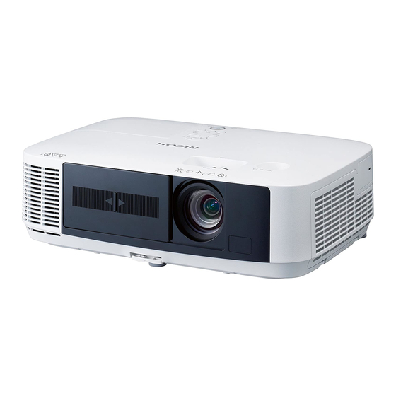
1. Product Information Overview Front / Top Lamp Cover Ventilation (outlet) Lens Cover Lens Adjustable Tilt Foot Lever Adjustable Tilt Foot Controls Focus Lever Zoom Lever Lens Shift Dial (Vertical) Ventilation (inlet) / Filter Cover... -
Page 13: Rear
Overview Remote Sensor Rear Port Cover for USB Wireless LAN Unit Monaural Speaker Terminal Panel AC Input Remote Sensor Built-in Security Slot Security chain opening Rear Foot... -
Page 14: Top Features
1. Product Information Top Features • While an on-screen menu is displayed, you can use the , , , and buttons to select the item you want to set Buttons or adjust. Used for both volume • When the on-screen menu is not displayed, the and adjustment and trapezoid buttons can be used to adjust the volume level, and the correction (Keystone Buttons). -
Page 15: Terminal Panel Features
Overview Turn the projector on and then off (standby). To turn the projector off (standby), then press the Power Power Button button one time. When the confirmation message appears on the screen, press the Power button again. Status Indicator p.119 Returns to the previous hierarchical menu in the currently displayed on-screen menu. - Page 16 1. Product Information Computer 2 Audio In Mini Jack (Stereo Mini) Computer 2 In / Component Input Connector (Mini D-Sub 15 Pin) S-Video In Connector (Mini DIN 4 Pin) Computer 1 Audio In Mini Jack (Stereo Mini) Computer 1 In / Component Input Connector (Mini D-Sub 15 Pin) Audio Out Mini Jack (Stereo Mini) PC Control Port (D-Sub 9 Pin) Monitor Out (Comp.1) Connector (Mini D-Sub 15 Pin)
-
Page 17: Part Names Of The Remote Control
Overview Part Names of the Remote Control Infrared Transmitter Pressing the Power button once displays the power-off confirmation Power Standby Button message. Pressing the Power button a second time turns the projector off (standby). Confirm that the projector is in standby (the Power indicator is lit orange*), and then turn it on. - Page 18 1. Product Information Select the COMPUTER1/2 input or a component. Computer 1/2/3 Button (Computer 3 button is not available.) S-Video Button Select the S-VIDEO input. Video Button Select the VIDEO input. Network Button Select the Network. Viewer Button Select the Viewer. The remote controller that comes with this projector can be used to ID Set Button control multiple projectors.
- Page 19 Overview The remote controller that comes with this projector can be used to control multiple projectors. These buttons are used to enter the ID Numeric Keypad (or set the control ID) of an individual projector. Button/Clear Button The Clear button can be used to clear the set control ID. Displays the current video image as a still image.
- Page 20 1. Product Information...
-
Page 21: Installation
2. Installation Installation Requirements • Do not use any other object than the projector’s sliding lens cover to cover the lens while the projector is on. • Doing so can cause the object to get extremely hot, and possibly resulting in a fire or damage due to the heat emitted from the light output. - Page 22 2. Installation • The projector is designed to operate on a power supply of 100-240V AC 50/60 Hz. Ensure that your power supply fits this requirement before attempting to use your projector. • Do not look into the lens while the projector is on. Serious damage to your eyes could result. •...
- Page 23 Installation Requirements • Do not send the projector in the soft case by parcel delivery service or cargo shipment. The projector inside the soft case could be damaged. • Select [HIGH] in Fan mode if you continue to use the projector for consecutive days. (From the menu, select [SETUP] [OPTIONS(1)] [FAN MODE]...
- Page 24 2. Installation • DO NOT TOUCH THE LAMP immediately after it has been used. It will be extremely hot. Turn the projector off and then disconnect the power cord. Allow at least one hour for the lamp to cool before handling. •...
- Page 25 Installation Requirements...
- Page 26 2. Installation...
-
Page 27: Replacement And Adjustment
3. Replacement and Adjustment Cautions for Maintenance Service Method of starting the set without TOP COVER and LAMP COVER How to start the set under the condition that the LAMP COVER and TOP COVER are removed The Lamp Cover switch of this model is mounted on the PCB Main Ass'y. The set cannot be started if the LAMP COVER and TOP COVER are left removed. - Page 28 3. Replacement and Adjustment Fold the carton (or cardboard paper) in the center in Character V. [A] : 3P extension board and 3P extension connector [B] : The lens cover is left opened. [C] : LAMP COVER SWITCH (ON by PUSH) [D] : Insert the carton Insert the carton (or cardboard paper) folded in Character V in the right side of the Lamp Cover switch.
- Page 29 Cautions for Maintenance Service • When installing the LAMP COVER and TOP COVER on the set, the TOP COVER only should be mounted first. Then, the LAMP COVER can be mounted. • If the installation work is carried out in the state that the LAMP COVER is mounted on the TOP COVER, the Lamp Cover switch may be damaged by the embossed part of the LAMP COVER.
-
Page 30: Special Tools
3. Replacement and Adjustment Special Tools • RS232C cable (cross) • LAN cable (Category 5 or higher) Adjusting jig for Adjustment of the optical axis Item name Application Part No. Photo taken from life For LCD PANEL Extension connector (40P) Y0135213 (R/G/B : 600mm) For LCD PANEL... - Page 31 Special Tools Item name Application Part No. Photo taken from life For FAN (POF2/POF5 : 900W) Extension connector (3P) Y0135203 For SHUTTER SW (PORMMF : 900mm) For FAN Extension connector PWB (POF2/POF5) Y0135204 (3P) For SHUTTER SW For THERMISTOR Extension connector (2P) Y0135201 (POTH-E/POTH-I : 900mm)
- Page 32 3. Replacement and Adjustment Insert the FFC cable in the relevant connector on the PWB. Let the embossed part (framed part in blue, shown below) fall down in the direction of the red arrow. * The embossed pat for fixing the FFC cable is fragile. Handle it with care when installing or removing the FFC cable.
-
Page 33: Parts Replacement
Parts Replacement Parts Replacement Lamp Unit Loosen the screw and remove the Lamp cover ( ×1). Loosen the screw and remove the Lamp unit ( ×2). -
Page 34: Filters
3. Replacement and Adjustment Filters Remove the Filter cover. Remove the Filters. -
Page 35: Port Cover For Usb Wireless Lan Unit
Parts Replacement [A] : Air filter A [B] : Notch [C] : Filter holder [D] : Projection [E] : Air filter B • When installing filter [A] in the holder, align the notch of the filter with the projection on the holder. Port Cover for USB Wireless LAN Unit Loosen the screw and remove the Port cover for USB wireless LAN unit ( ×1). - Page 36 3. Replacement and Adjustment Remove the Filters ( p.32). Top cover [A] ( ×8) When removing the top cover, make sure to keep the lens cover open. It might be difficult to remove the cover due to projections inside the chassis. Be careful not to damage the cover or other parts when removing the cover from inside the chassis.
-
Page 37: Pcb Shutter
Parts Replacement There is a cable connecting the TopCover to the main unit. Exercise care when removing the TopCover. PCB Shutter Top cover ( p.33). Remove the PCB Shutter ( ×1, ×1). -
Page 38: Rear Panel And Speaker
3. Replacement and Adjustment Rear Panel and Speaker Top cover ( p.33). - Page 39 Parts Replacement Remove the Main board unit ( ×6, ×15). Remove the screw ( ×1). Remove the bracket [A] ( ×3).
-
Page 40: Pcb Main Ass'y
3. Replacement and Adjustment Remove the connector ( ×1). PCB Main Ass'y • Require the software adjustment, When replacing the PCB Main Ass'y ( p.76). Please do the "Copying of all data", before removing the PCB Main Ass'y. PCB Main Ass'y ( p.36). -
Page 41: Lamp Fan
Parts Replacement PCB Network ( p.38). • When assembling the main board, align the position of the PCB Main Ass'y and PCB Network on- board connectors and press the portion marked [A] to fasten them securely. Lamp Fan Rear Panel and Speaker ( p.36). - Page 42 3. Replacement and Adjustment Remove the Lamp fan unit ( ×2). Remove the Lamp fan ( ×2). • When assembling the lamp fan, pay careful attention to where the bracket is inserted.
-
Page 43: Opt Base
Parts Replacement OPT Base • After replacing the OPT Base, Require the Software adjustment and Adjustment of the optical axis. PCB Main Ass'y ( p.38). Remove the Lens holder (top) ( ×4). Remove the OPT Base ( ×2). -
Page 44: Assembling The Lens Holder (Top)
3. Replacement and Adjustment Assembling the lens holder (top) Press the latch portion to remove zoom lever [A] and focus lever [B]. • The zoom and focus levers use the same parts. These parts can be used interchangeably. Place the lens cover over the OPTBase and screw it into place. [A] : Zoom ring [B] : Foucus ring •... - Page 45 Parts Replacement Align the protrusion of the zoom lever with the notch on the zoom ring. With the lever inclined on the engine side, push in the lens side until you hear it snap.
-
Page 46: Iris Unit
3. Replacement and Adjustment In the same way, install the focus lever. IRIS Unit PCB Main Ass'y ( p.38). -
Page 47: Ps-Converter
Parts Replacement Remove the barrier ( ×2). Remove the IRIS unit ( ×2). • When removing or installing the IRIS Unit, be careful not to damage the Integrator. PS-Converter Remove the IRIS unit ( p.44). -
Page 48: Lcd Fan 1
3. Replacement and Adjustment Remove the Integrator unit ( ×1). Remove the PS converter ( ×1). LCD Fan 1 Remove the Lamp fan ( p.39). Remove the OPT Base ( p.41). Remove the IRIS unit ( p.44). - Page 49 Parts Replacement Remove the Engine unit ( ×4). Remove the Lens holder (bottom) ( ×2). Remove the duct ( ×3).
-
Page 50: Lcd Fan 2
3. Replacement and Adjustment Remove the LCD fan unit ( ×4). Remove the LCD fan ( ×2). LCD Fan 2 Remove the LCD fan unit ( p.46). Remove the LCD fan 2 ( ×2). -
Page 51: Pcb Remocon
Parts Replacement PCB Remocon Remove the LCD fan unit ( p.48). Remove the PCB remocon [A]. • When assembling the board, properly insert the PCB Remocon into the notch. -
Page 52: Intake Temp Sensor
3. Replacement and Adjustment Intake Temp Sensor Top cover ( p.33). Remove the intake temp sensor [A] ( ×1). Exhaust Temp Sensor Top cover ( p.33). Remove the Exhaust temp sensor ( ×1). -
Page 53: Exhaust Fan
Parts Replacement Exhaust Fan Remove the Exhaust temp sensor ( p.50). Remove the Exhaust fan cover ( ×2). -
Page 54: Thermostat
3. Replacement and Adjustment Remove the Exhaust fan. Remove the rubber buffer. • The rubber buffer is reused when replacing parts. Handle it carefully. Thermostat Remove the Lamp fan ( p.39). Remove the Exhaust fan cover ( p.51). - Page 55 Parts Replacement Remove the bracket [A] ( ×2). Remove the screw ( ×1). Remove the barrier.
- Page 56 3. Replacement and Adjustment Remove the bracket ( ×2). Remove the pin [A] and Thermostat. • When assembling the projector, position the print side of the Thermostat to face you. • Firmly insert the pin all the way.
-
Page 57: Psu Fan
Parts Replacement PSU Fan Remove the Exhaust fan cover ( p.51). -
Page 58: Power Supply-Ballast
3. Replacement and Adjustment Remove the bracket ( ×2). Remove the PSU fan [A]. Power Supply-Ballast Remove the PSU Fan ( p.55). Remove the Power supply-ballast ( ×3, ×2). Power Supply-DC Remove the Lamp fan ( p.39). - Page 59 Parts Replacement Remove the Power Supply-Ballast ( p.56). Remove the bracket [A] ( ×2). Remove the screw ( ×1).
- Page 60 3. Replacement and Adjustment Remove the barrier. Remove the bracket ( ×2). Remove the bracket [A] ( ×3). Remove the Power supply-DC ( ×4 ×1).
-
Page 61: Bottom Cover
Parts Replacement Bottom Cover Remove the LCD fan unit ( p.46). Remove the Thermostat ( p.52). Remove the Power supply-DC ( p.56). -
Page 62: Replacement Of Optical Parts
3. Replacement and Adjustment Replacement of Optical Parts Adjustments needed after the replacement of parts are as specified in the table below. : Adjustment needed : Need checking Disassembly/replacement of parts Adjustment parts Polarizing parts OPT BASE RL2 adjustments CLG adjustments CLB adjustments POLARIZER R SASSY POLARIZER G SASSY... -
Page 63: Polarizer-G
[B] : Make sure to note the direction in which the Polarizer-B is set in the holder. You will notice a mark in the area enclosed by the blue circle in the figure. Polarizer-G PJ X5360N Remove the PCB Main Ass'y ( p.38). - Page 64 Remove the PCB Main Ass'y ( p.38). Remove the Filter (G) [A] ( ×1). Remove the Polarizer-G [A] ( ×1). • Polarizer-G No need to adjust filter. • Insertion and removal of the polarizing plate is the same as PJ X5360N.
-
Page 65: Polarizer-R
Replacement of Optical Parts Polarizer-R Remove the PCB Main Ass'y ( p.38). Remove the Polarizer-R [A] ( ×1). [B] : Make sure to note the direction in which the Polarizer-R is set in the holder. You will notice a mark in the area enclosed by the blue circle in the figure. Optical Parts Adjustment Adjustments needed after the replacement of polarization plates. -
Page 66: Adjusting And Fixing Parts
3. Replacement and Adjustment Adjusting and fixing parts PJ X5360N [A] : RL2 [B] : RL2 Fixing screw [C] : Polarization plate (R) [D] : Polarization plate fixing screw (R) [E] : Polarization plate (B) [F] : Polarization plate fixing screw (B) -
Page 67: Adjustment Of The Optical Axis (Shadow Adjustment)
Replacement of Optical Parts PJ WX5350N [A] : RL2 [B] : RL2 Fixing screw [C] : Polarization plate (R) [D] : Polarization plate fixing screw (R) [E] : Polarization plate (B) [F] : Polarization plate fixing screw (B) [G] : CLB [H] : CLB fixing screw [I] : CLG [J] : CLG Fixing screw... - Page 68 3. Replacement and Adjustment Remove the PCB Main Ass'y ( p.38). [A] : To FAN POF2 (3P) [B] : To TH-I PWB (2P) [C] : To FAN POF1(4P) [D] : To R/G/B LCD (40P) [E] : To BS(5P) [F] : To FAN POF5 (3P) [G] : To TH-E (2P) [H] : To FAN POF4 (4P) [I] : To PCB Shutter (3P)
- Page 69 Replacement of Optical Parts Install the extension connectors and Thermostat on the PCB Main Ass’y that has been dislodged. Connect the respective connectors of the set with the extension connector PWB. EXPERT (Test Pattern)
- Page 70 3. Replacement and Adjustment Test Pattern (Display) Start the set. Display an internal pattern (all-white signal). (Set the machine to EXPERT or SERVICE mode, then select [SETUP] to display [TEST PATTERNDISPLAY].) Make shadow adjustments. After the completion of adjustments, recover the original status. Shadow adjustment flow...
- Page 71 Replacement of Optical Parts Handling of margin in shadow adjustment During shadow adjustment, adjust the margin so that it is balanced vertically and horizontally. If adjustments are carried out from the LCD panel, this margin cannot be seen directly. Therefore, try to move the shadow until its top, bottom, right, or left part appears.
- Page 72 3. Replacement and Adjustment [A] : Shadow in vertical direction [B] : Shadow in vertical direction Neutral setup position for each adjuster block • CLG Vertical : The holder (CLG) shall be positioned at the height of two spacers (RL2) T1.0. Horizontal : Bosses of Cover (OPT) are located in the right and left holder (CLG) holes, each in the center position.
- Page 73 Replacement of Optical Parts [A] : Handle part of the holder (CLG) [B] : Spacer (RL2) [C] : Fixing screw Vertical direction: 1. Loosen the CLG fixing screw (in 1 position) sufficiently. 2. Change the spacer (RL2) thickness and adjust the shadow margin so that it is vertically equalized. Arrange the spacer so that its total quantity can be reduced.
- Page 74 3. Replacement and Adjustment 2. Change the spacer (RL2) thickness and adjust the shadow margin until it is vertically equalized. Arrange the spacer so that its total quantity can be reduced. Horizontal direction: 1. Hold the handle part of the holder (RL2) by hand and move the holder to the right and left in order to adjust the shadow margin so that it is horizontally equalized.
-
Page 75: Adjustment Of The Polarization Plate (Contrast Adjustment)
Replacement of Optical Parts (Make adjustments until the portions in magenta color are eliminated vertically and uniformly in the projector screen.) • Horizontal shadow adjustment for G and R Move the holder (CLG) horizontally and eliminate the horizontal shadow. (Equally balanced in horizontal directions) (Make adjustments until the portions in magenta color are eliminated horizontally and uniformly in the projector screen.) - Page 76 3. Replacement and Adjustment [A] : To FAN POF2 (3P) [B] : To TH-I PWB (2P) [C] : To FAN POF1(4P) [D] : To R/G/B LCD (40P) [E] : To BS(5P) [F] : To FAN POF5 (3P) [G] : To TH-E (2P) [H] : To FAN POF4 (4P) [I] : To PCB Shutter (3P) [J] : To PS (16P)
- Page 77 Replacement of Optical Parts Install the extension connectors and Thermostat on the PCB Main Ass’y that has been dislodged. Connect the respective connectors of the set with the extension connector PWB. Start the set. Display an internal pattern (all-black signal). (Select Install and Setup on the menu screen and set the background at Black Background.) Adjust the polarization plate.
-
Page 78: Electrical Adjustment
3. Replacement and Adjustment Electrical Adjustment Adjustments needed after the replacement of Main PWB is as specified in the table below. : Adjustments needed : Data Read/Write : This is needed, depending on the situation. PCB Main OPT Base Ass’y Data writing Data for each model EDID Data... -
Page 79: Procedures For The Replacement Of The Pcb Main Ass'y
Electrical Adjustment Writes BIOS data, Firmware, Firm and data for each CPU, set device (IC) values, a temperature table for cooling, and adjusted VT values. • EDID Data Writes Model-related data for each model used for communication with a PC. If this value is incorrect, the PC may be unable to recognize a XGA/WXGA mode. -
Page 80: Pc Control Software For Service
3. Replacement and Adjustment PC control software for service Outline of software descriptions This is the PC control software for servicing adjustments to be conducted during the replacement of the PCB Main Ass’y or LDC panel (OPT BASE). This software makes it possible to perform the following adjustments: •... - Page 81 Electrical Adjustment Assure a condition that PJ and PC are connected through a serial cable and start the service adjustment software. Click [Setup] button to open the Setup window.
- Page 82 3. Replacement and Adjustment Select the COM port connected to the PJ in the [Port] box. Set the baud rate match the setting of the PJ. Press [Return] button when the setting is completed. Click “Adjust Start” to start initial data reading. * Each adjusting button will be enabled when models are correctly identified.
- Page 83 Electrical Adjustment Click [Data] button of the service software with the PJ Power in standby to open the Data window. According to (1) and (2) below, follow the steps of All Data Read / Write. All Data mentioned here denote the respective factory adjusting data (Flicker, VT, Uniformity, Color Correction, Wall Color), and Usage Time.
- Page 84 3. Replacement and Adjustment All Data Read Read the PCB Main Ass’y data currently used before replacement and save them in a file. Check mark the [All data], and click [Read] button. Name the file and save. The procedure is done when a message box “It completed.” is displayed. * In a certain faulty state, data cannot be saved.
- Page 85 Electrical Adjustment All Data Write After exchanging PCB Main Ass’y, click [Write] button to select the saved file. When a message “Please Power Off (Standby state).” is displayed, make sure that the PJ Power is in standby, then click [OK] button. The procedure is done when a message box “It completed.”...
- Page 86 3. Replacement and Adjustment * When executing data writing, [Data] indicated in the main window turns to bold text. Adjustment of Flicker Click [Flicker] button of the service software to open the Flicker Adjust window. Make Flicker adjustments according to (1) ~ (3) below. Adjustment start Keeping the PJ power supply turned ON, maintain the condition of aging for five minutes.
- Page 87 Electrical Adjustment Adjustment of Floor Check [Floor]. Display Red raster signal by clicking [Test R] button in the [Test Pattern] box. Adjust R-scroll bar so that the flicker in the middle of the window becomes smallest. Display Green raster signal by clicking [Test G] button in the [Test Pattern] box. Adjust G-scroll bar so that the flicker in the middle of the window becomes smallest.
- Page 88 3. Replacement and Adjustment Display Blue raster signal by clicking [Test B] button in the [Test Pattern] box. Adjust B-scroll bar so that the flicker in the middle of the window becomes smallest. When flicker adjustment is done, click [SET] button in the [Data] box to write the adjusted value.
- Page 89 Electrical Adjustment Adjustment of Ceiling Check [Ceiling]. Display Red raster signal by clicking [Test R] button in the [Test Pattern] box. Adjust R-scroll bar so that the flicker in the middle of the window becomes smallest. Display Green raster signal by clicking [Test G] button in the [Test Pattern] box. Adjust G-scroll bar so that the flicker in the middle of the window becomes smallest.
- Page 90 3. Replacement and Adjustment Click [Usage Time] button of the service software with the PJ Power in standby to open Usage Time Setting window. Make Usage Time setup according to (1) below.
- Page 91 Electrical Adjustment Setting Select a type of Usage Time to be changed in the [Change Usage Time]. Set time using the scroll bar, then click [SET] in the Data Box. When a message [Please Power Off (Standby state).] is displayed, make sure that the PJ Power is in standby, then click [OK] button.
- Page 92 • “File format error”, “Address error” The data format of the file specified when executing data writing from the file is not correct. Make sure that it is a file read in PJ X5360N/PJ WX5350N. • “ACK Error!!” Check the status of the PJ, and retry.
-
Page 93: Model-Specific Data Writing Procedure
Electrical Adjustment In case it occurs 2 or 3 times consecutively, reboot the PC. If not recovering from this error after operating the above, the PJ may be in trouble. Model-Specific Data Writing Procedure Model-specific data writing procedure Model-related data for each model Writing software : PJUpgrader2.exe File name to be written : *********_mdata.bin Initial setting of writing software... - Page 94 3. Replacement and Adjustment Release the [MENU] and [EXIT] keys when the Power LED blinks in green.
- Page 95 Electrical Adjustment Start up PJUpgrader2.exe previously installed. Press [choose….] button to select the file (*****_mdata_******.bin) to be written. Check that the set and PC are properly connected each other, then press [Flash] button. Message "Do you start flash write?" is displayed. When [Yes(Y)] button is pressed, writing is started.
-
Page 96: Procedure For Rewriting Edid Data
The projector connected is not that the selected file can write for. Procedure for rewriting EDID data Outline software descriptions This is PC control software to rewrite EDID data of PCB Main Ass’y supporting PJ X5360N/ WX5350N. Equipment to be used and environment Equipment to be used •... - Page 97 Electrical Adjustment Software installation procedures Installing EDIDwriter Copy all files of “EDIDwriter” into any folder. Installing EDIDdata Copy each EDID data to any folder, and execute. Rewrite procedure * Make sure to follow the procedure below to rewrite the data. •...
- Page 98 3. Replacement and Adjustment Initial setting Turn the Power OFF for the PJ main unit. (AC source turned on) Connect the PJ and the PC with a serial cable, referring to "2. Equipment to be used and environment" Then activate "EDIDwriter". •...
- Page 99 Electrical Adjustment Selecting a writing file Click "Choose.." button to select the file. * Select HDMI EDID data from File name “yyyy_ EDID_HDMI_V***.bin”. (yyyy:Model, xxx:version). • Comparison Table of Model Names and EDID File Names of HDMI Model Name EDID File Name PJ-X5360N X5360N_EDID_HDMI_V***.bin PJ-WX5350N...
- Page 100 3. Replacement and Adjustment Rewriting data Make sure that the PJ and the PC are properly connected, and then click "Flash" button. Rewriting HDMI terminal EDID is started. When writing is completed, the message "Write Finished!" will be displayed. Click "OK" button to finish the procedure. Rewriting D-SUB terminal EDID...
- Page 101 Electrical Adjustment Initial setting Turn the Power OFF for the PJ main unit. (AC source turned on) Connect the PJ and the PC with a RGB cable, referring to "2. Equipment to be used and environment". Then activate "EDIDwriter". • Mode Select "Flash".
- Page 102 3. Replacement and Adjustment Selecting a writing file Click "Choose.." button to select the file. * Select D-SUB EDID data from File name “yyyy_ EDID_DSUB_V***.bin”. (yyyy:Model series name, xxx: version) • Comparison Table of Model Names and Analog EDID File Names Model Name EDID File Name PJ-X5360N...
- Page 103 Electrical Adjustment Press the select keys in the order of [ ] [Enter]. Press the [Menu] key to obtain a menu display and confirm that [SERVICE] is displayed in lower part of the menu. Rewriting data Make sure that the PJ and the PC is properly connected, and then click "Flash" button. It is not necessary that the PC image is displayed on the PJ at this time.
- Page 104 3. Replacement and Adjustment The serial port has failed to open. Check whether any available serial port has been selected. There is no response from the PJ. Check whether the PC and the PJ are connected through a serial cable. There was a Nack response from the PJ.
-
Page 105: Procedure For Writing Of A Serial Number And A Model Number
Electrical Adjustment The PJ is not found. Check whether the PC and the PJ are connected through an RGB cable. A wrong model is specified. Check the model. Procedure for writing of a serial number and a model number Software installation... - Page 106 3. Replacement and Adjustment Decompress snwriter000002.zip; and execute the established set-up.exe to install it in the PC. (For the destination folder for installation, either half-size or full-size font characters are acceptable.) Writing of a serial number and a model number Connect the Projector to computer through an RS-232C cable (Reverse) (D-SUB9pin - D-SUB9pin).
- Page 107 Electrical Adjustment Data readout The data (model number and serial number) written in the projector are read out. When the “Read” button is pressed, the data read out of the projector are displayed in Column [B] in the specified format. In regard to “baud rate”...
-
Page 108: Procedures For The Replacement Of The Opt Base
3. Replacement and Adjustment Procedures for the replacement of the OPT Base After the replacement of PCB Main Ass’y Flicker adjustments ( PC control software for service) -
Page 109: System Maintenance
4. System Maintenance Firmware Upgrade A LAN cable is needed to upgrade the firmware. Before upgrading the firmware, make sure to prepare the following: • LAN cable • Notebook PC (on which Internet Explorer 6.0 or later is installed) Upgrading the firmware Connect the PC to the projector via a wired or wireless LAN. - Page 110 4. System Maintenance Select the file and press the [UPDATE] button. When the confirmation dialog box appears, press the [OK] button. When the message "File written successfully" appears in the history section, press the [REBOOT] button to restart the projector. To update multiple files, repeat steps 5 to 7 for each file you want to update.
-
Page 111: Functional Test
Functional Test Functional Test Connecting a Computer Signals supported by Plug & Play (DDC2) INPUT Computer 1 In Computer 2 In HDMI analog analog digital [A] : A commercially available USB cable (compatible with USB 2.0 specifications) [B] : HDMI cable (not supplied), Use High Speed HDMI® Cable. [C] : Stereo mini-plug audio cable (not supplied) [D] : Computer cable (VGA) (supplied) - Page 112 4. System Maintenance To mini D-Sub 15-pin connector on the projector. It is recommended that you use a commercially available distribution amplifier if connecting a signal cable longer than the cable supplied. • For Macintosh, use a commercially available pin adapter (not supplied) to connect to your Mac’s video port.
- Page 113 Functional Test • Some graphics cards have both analog RGB (15-pin D-Sub) and DVI (or DFP) outputs. Use of the 15-pin D-Sub connector may result in no picture being displayed from the digital output of the graphics card. • Do not disconnect the DVI-to-HDMI cable while the projector is running. If the signal cable has been disconnected and then reconnected, an image may not be correctly displayed.
-
Page 114: Connecting An External Monitor
4. System Maintenance Connecting an External Monitor [A] : Computer cable (VGA) (not supplied) [B] : Computer cable (VGA) (supplied) [C] : Stereo mini-plug audio cable (not supplied) You can connect a separate, external monitor to your projector to simultaneously view on a monitor the computer analog image you’re projecting. -
Page 115: Connecting A Dvd Player Or Other Av Equipment
Functional Test Connecting a DVD Player or Other AV Equipment Connecting Video/S-Video Input [A] : S-Video cable (not supplied) [B] : Video cable (not supplied) [C] : Audio cable (not supplied) [D] : Audio equipment [E] : Audio cable (not supplied) •... -
Page 116: Connecting Component Input
4. System Maintenance • The Audio In L and R jacks (RCA) are shared between the Video and S-Video inputs. • Refer to your VCR owner’s manual for more information about your equipment’s video output requirements. • An image may not be displayed correctly when a Video or S-Video source is played back in fast- forward or fast-rewind via a scan converter. -
Page 117: Connecting Hdmi Input
Functional Test [A] : Stereo mini plug - to - RCA audio cable (not supplied) [B] : Monitor cable Stereo mini plug - to - RCA able Mini D-sub 15P-BNC (not supplied) [C] : Conversion adapter BNC-pin (not supplied) To Y/Cb/Cr output Green(Y)/Blue(Cb)/Red (Cr) [D] : Audio cable (not supplied) [E] : Audio Equipment [F] : DVD player... - Page 118 4. System Maintenance ® [A] : HDMI cable (not supplied) Use High Speed HDMI Cable. [B] : Audio cable (not supplied) Input button on the projector Input connector Button on the remote control cabinet HDMI IN HDMI HDMI • For users of audio video equipment with an HDMI connector: •...
-
Page 119: Connecting To A Wired Lan
Functional Test • When connecting the HDMI In connector of the projector to the DVD player, the projector’s video level can be made settings in accordance with the DVD player’s video level. In the menu select [HDMI SETTINGS] [RGB INPUT RANGE] and make necessary settings. •... -
Page 120: Input Signals
4. System Maintenance Input signals Signal level RGB signal 0.7Vp-p/75 1.0Vp-p/75 (Signal Y) Component signal 0.7Vp-p/75 (Cb/Cr, Signal Pb/Pr) VIDEO signal 1.0Vp-p/75 1.0Vp-p/75 (Signal Y) S-VIDEO signal 0.286Vp-p/75 (Signal C burst level) Sync signal TTL Level (Positive/Negative polarity)/ 1k Audio signal 0.5Vrms/22k or more RGB signal frequencies Horizontal sync frequency... -
Page 121: Troubleshooting
5. Troubleshooting LED Display Indicator Messages Power Indicator Indicator Condition Projector Condition Note The main power is off Blue (short flashes) The projector is getting ready to turn on. Wait for a moment. Blinking light Blue (long flashes) Off Timer is enabled. Blue The projector is turned on. -
Page 122: Lamp Indicator
5. Troubleshooting Lamp cover error or Replace the lamp cover or lamp housing Red (cycles of 1) lamp housing error correctly. The projector is overheated. Move the Red (cycles of 2) Temperature error projector to a cooler location. Power unit is not working properly. Contact Red (cycles of 3) Power error your dealer. -
Page 123: Over-Temperature Protection
LED Display Lamp has been used beyond its limit. The projector will not turn on until the lamp is Replace the lamp. Steady replaced. light [LAMP POWER] is set to [AUTO ECO] or Green [ECO1] Over-Temperature Protection If the temperature inside the projector rises too high, the over-temperature protector will automatically turn off the lamp with the Status indicator blinking (2-cycle On and Off.) Should this happen, do the following: •... -
Page 124: Service Mode
5. Troubleshooting Service Mode List of functions Function EXPERT SERVICE VS BEGIN CLAMP TIMING SYNC PROTECTION UPPER SYNC PROTECTION LOWER VIDEO FILTER TEST PATTERN2 COLOR UNIFORMITY WHITE UNIFORMITY (All white color unevenness adjustment function) SYNCHRONIZE REF. WHITE BALANCE KEYSTONE CONFIGURATION (Horizontal adjustment) MESSAGE CLEAR PANEL HOURS... -
Page 125: Service Mode
Service Mode • In the state of Power ON, press each key in the order of [HELP] [HELP]. • Press the [MENU] key to display the menu and confirm that [Expert] is displayed below the menu. Service mode (for service) •... -
Page 126: Contents Of Display
5. Troubleshooting • Recover the standby state by pressing the [POWER] key. When this action is taken, the original status can also be recovered at the time of next starting. Contents of display When the service mode or the expert mode is assumed, the menu is added with the functions specified below. -
Page 127: Setup-Expert2 Tab
Service Mode In the gray bars, ON/OFF switching is impossible for Red, Green, Blue, and Invert. When a test pattern is displayed in the state that no input signal is applied, Picture Management setup is effected in the High Bright mode. SETUP–EXPERT2 Tab Mesage Display or non-display of the following messages is set up:... -
Page 128: Mm Viewer And Network Area
5. Troubleshooting Displayed keyword Key data sent to the user DOWN LEFT RIGHT MM Viewer and Network Area List of functions MM function EXPERT SERVICE Viewer – Check pattern Network – PING IMAGE EXPRESS UTILITY – Detailed setup DESKTOP CONTROL UTILITY – Detailed setup Network setup –... -
Page 129: Additional Functions
Service Mode Additional Functions Viewer – Check Pattern The video data saved in the PJ are displayed. Network – PING When an address is put in the IP Address item for execution, the result is displayed in the Result item. To take this action repeatedly, a check mark should be put in the “Repeat”... - Page 130 5. Troubleshooting • Profile Profile1 ~ Profile4 is specified. • Subnet registration A subnet is registered. • Host address A host address is registered. • Host subnet mask A host subnet mask is specified when a checkmark is given to the subnet being registered. Network service –...
-
Page 131: Troubleshooting Guide
Troubleshooting Guide Troubleshooting Guide Operation check It is possible to conduct a certain level of fault diagnosis in normal state of operation check. Before removing the top cover, check the indicator. Factors related to starting... - Page 132 5. Troubleshooting Factors related to operation These items are often caused by confusion such that the menu setup has been wrongly made. 1. The Power is not ON even though the Power switch is pressed in the standby state (POWER LED lit in orange, and STATUS LED in green) 2.
-
Page 133: Power Block
Troubleshooting Guide * Confirmation for the Test Pattern display of the Expert Mode menu is effective as an examination program even at the time of input entry at the Video / S-Video terminal. Power block If the power does not start. (Power LED is not lit) RTB 6 This flow chart was changed... -
Page 134: For Video
5. Troubleshooting If the power does not start. (Power LED is not blue) For Video The picture is not displayed correctly Com1/Com2. -
Page 135: For Audio
Troubleshooting Guide For Audio Does not output sound from the speaker. -
Page 136: Error Log
5. Troubleshooting Error Log Error Log Screen Image Displaying an error log screen The error log screen is displayed by long-pressing the [MENU] button five seconds or more in user, expert, or service mode. Service Information: Page-1 User mode / Expert mode Service mode: Display of other areas added... -
Page 137: Service Information: Page-2
Error Log Service Information: Page-2 User mode / Expert mode Service mode: Display of lamp voltage added... -
Page 138: Service Information: Reset
5. Troubleshooting Service Information: Reset Not related to the menu mode... -
Page 139: Contents Of Error Log (Page1) Display
Error Log Contents of Error Log (Page1) Display * Cleared with All Data Reset from the service menu. Status Columns List of Phenomena caused by Power OFF due to Errors Display Meaning Details Possible cause symbol E1-1 Status LED blinking once Cover malfunction Lamp cover E2-1... -
Page 140: Pj Usage Columns
5. Troubleshooting Display Meaning Details Possible cause symbol E9-1 Status LED blinking 9 times Iris error (calibration) Iris PJ Usage Columns Display of projector usage time (Projector Hours Used) when an error emerges TEMP Columns Display of temperature information when an error emerges Displayed in the order of [Suction Air], [Lamp], [Exhaust Air], [Ballast] from left to right. -
Page 141: Contents Of Error Log (Page2) Display
Error Log Contents of Error Log (Page2) Display TEMP Columns Present temperature information is displayed. Displayed in the order of [Suction Air], [Lamp], [Exhaust Air], [Ballast] from left to right. Lamp/Filter Clear Count The number of reset actions is displayed in regard to Lamp Usage / Filter Usage. Displayed in the order of [No. -
Page 142: Lamp Voltage: Indicated Exceeding The Service Power
5. Troubleshooting Lamp Voltage: Indicated exceeding the Service Power The present status of lamp ballast voltage is displayed. Contents of Error Log (Reset) Display ALL DATA All Data Reset is executed according to the User Menu mode. - Page 143 Model Rigel-PJ1 Machine Codes: Y015/Y016 Appendices 6 January, 2012...
- Page 144 TABLE OF CONTENTS 1. Appendix: Specifications General Specifications............................3 List of General Specifications........................3 List of Supported Signals..........................6...
- Page 146 1. Appendix: Specifications General Specifications List of General Specifications Optical PJ X5360N PJ WX5350N 0.63 inch LCD with Micro Lens Array 0.59 inch LCD with Micro Lens Array LCD Panel (Aspect Ratio 4:3) (Aspect Ratio 16:10) Resolution 1024 × 768 pixels (XGA) 1280 ×...
- Page 147 1. Appendix: Specifications *3 Compliance with ISO21118-2005 Electrical PJ X5360N PJ WX5350N ® 2 × RGB/Component (D-Sub 15 P), 1 × HDMI Type A (HDMI Connector) Inputs HDCP supported , 1 × S-Video (DIN 4 P), 1 × Video (RCA), 1 × (L/R) RCA Audio, 2 ×...
- Page 148 General Specifications PJ X5360N PJ WX5350N MODE 358 W (100-130 V)/343 W (200-240 V) (NORMAL) ECO1 271 W (100-130 V)/264 W (200-240 V) MODE Cons umpt STANDBY 9 W (100-130 V/200-240 V) (NORMAL) STANDBY 0.2 W (100-130 V)/0.4 W (200-240 V)
-
Page 149: List Of Supported Signals
1. Appendix: Specifications PJ X5360N PJ WX5350N Operational Temperatures : 41° to 104°F (5° to 40°C), (ECO mode selected automatically at 95°F to 104°F/35°C to 40°C) Environmental 20% to 80% humidity (non-condensing) Considerations Storage Temperatures : 14° to 122°F (-10° to 50°C),... - Page 150 General Specifications Signal Resolution ( dots ) Aspect Ratio Refresh Rate ( Hz ) SXGA 1280 × 1024 5 : 4 60/75 SXGA+ 1400 × 1050 4 : 3 WXGA+ 1440 × 900 16 : 10 WXGA++ 1600 × 900 16 : 9 UXGA 1600 ×...
- Page 151 4 : 3 / 16 : 9 Composite Video/S-Video Signal Aspect Ratio Refresh Rate ( Hz ) NTSC 4 : 3 4 : 3 PAL60 4 : 3 SECAM 4 : 3 *1 Native resolution on XGA model (PJ X5360N)
- Page 152 General Specifications *2 Native resolution on WXGA model (PJ WX5350N) *3 The projector may fail to display these signals correctly when [NORMAL] is selected for [ASPECT] in the on-screen menu. The factory default is [NORMAL] for [ASPECT]. To display these signals, select [16:9] for [ASPECT]. •...
- Page 153 MEMO...
- Page 154 MEMO...
- Page 155 MEMO...
Need help?
Do you have a question about the PJ X5360N and is the answer not in the manual?
Questions and answers