Pepperl+Fuchs KFD0-TR-1 System Manual

Pepperl+Fuchs KFD0-TR-1 System Manual

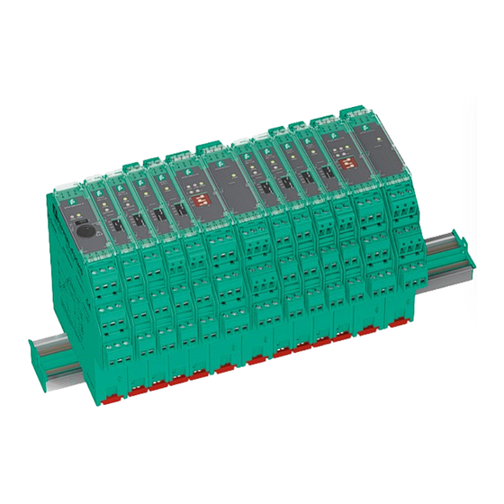
K-system signal conditioners

Advertisement

Quick Links

K-System
Signal Conditioners
System Manual
ISO9001

Advertisement

Table of Contents
loading

Summary of Contents for Pepperl+Fuchs KFD0-TR-1

  • Page 1 K-System Signal Conditioners System Manual ISO9001...
  • Page 2 Phone: +49 621 776 - 0 E-mail: info@de.pepperl-fuchs.com North American Headquarters Pepperl+Fuchs Inc. 1600 Enterprise Parkway Twinsburg, Ohio 44087 Phone: +1 330 425-3555 E-mail: sales@us.pepperl-fuchs.com Asia Headquarters Pepperl+Fuchs Pte. Ltd. P+F Building 18 Ayer Rajah Crescent Singapore 139942 Phone: +65 6779-9091 E-mail: sales@sg.pepperl-fuchs.com https://www.pepperl-fuchs.com...
  • Page 3: Table Of Contents

    K-System – Signal Conditioners Contents Introduction ............5 Content of this Document .
  • Page 4 K-System – Signal Conditioners Contents...
  • Page 5: Introduction

    K-System – Signal Conditioners Introduction Introduction Content of this Document This document contains information that you need in order to use your product throughout the applicable stages of the product life cycle. These can include the following: • Product identification •...
  • Page 6: Target Group, Personnel

    K-System – Signal Conditioners Introduction Target Group, Personnel Responsibility for planning, assembly, commissioning, operation, maintenance, and dismounting lies with the plant operator. Only appropriately trained and qualified personnel may carry out mounting, installation, commissioning, operation, maintenance, and dismounting of the product. The personnel must have read and understood the instruction manual and the further documentation.
  • Page 7: Product Specifications

    K-System – Signal Conditioners Product Specifications Product Specifications Function Signal conditioners are isolators used for the galvanic isolation of non-intrinsically safe applications. Signal conditioners have the necessary current and voltage limitation between field circuit and control. Sensor Control system Actuator Figure 2.1 Function –...
  • Page 8: Housing Styles

    K-System – Signal Conditioners Product Specifications Housing Styles Depending on the functionality and application, K-System devices have 3 different housing widths: • KC devices with 12.5 mm width • KF devices with 20 mm width • KF devices or KH devices with 40 mm width The 3 housing widths versions have the same system characteristics.
  • Page 9 K-System – Signal Conditioners Product Specifications KF Device Housing KFD2-SR2-2.2S OUT CHK PWR Figure 2.4 KF device housing (20 mm) Used for high channel density • Compact 20 mm housing • Packing density from 5 mm per channel KFD2-WAC2- RS232 Figure 2.5 KF device housing (40 mm) Used for applications with high functionality...
  • Page 10: Terminals

    K-System – Signal Conditioners Product Specifications Terminals 2.3.1 Removable Terminal Blocks The removable terminal blocks simplify connection and control cabinet assembly. The terminal blocks offer space for the connection of leads with core cross-sections of up to 2.5 mm (14 AWG). The terminal blocks are coded with red coding pins so misconnection of terminal blocks are eliminated.
  • Page 11 K-System – Signal Conditioners Product Specifications Protection against direct contact The removable terminal blocks have different heights: • Height 15 mm (1), (2), (3): These terminal blocks are used in applications that have rated voltages lower than 50 V AC. The insulation of the removable terminal blocks provides protection against direct contact.
  • Page 12 K-System – Signal Conditioners Product Specifications 2.3.2 Terminal Designation Note See corresponding datasheets for precise terminal designation. 9 10 9 10 Figure 2.8 KC device housing (12.5 mm housing) 1 2 3 4 5 6 7 8 9 10 11 12 13 14 15 Figure 2.9 KF device housing (20 mm housing)
  • Page 13: Color Identification

    K-System – Signal Conditioners Product Specifications 1 2 3 4 5 6 7 8 9 10 11 12 13 14 15 16 17 18 19 20 21 22 23 24 Figure 2.10 KF device housing (40 mm) Color Identification The color identification of the devices has the following meaning: •...
  • Page 14: Status Indicators Of The Isolators

    K-System – Signal Conditioners Product Specifications Status Indicators of the Isolators LEDs are often used on isolators to indicate different statuses (e. g. for power supply, device failure, status messages, binary switching states). Standard LED colors are assigned to the status display according to NAMUR NE44. Display function Display Meaning...
  • Page 15: Operating Elements

    K-System – Signal Conditioners Product Specifications Operating Elements Many devices of the K-System can be adapted to different applications. Depending on the device different operating elements are available for this configuration. These operating elements are: DIP switches Via DIP switches you can configure the basic functions of the device. Figure 2.13 DIP switch Rotary switches...
  • Page 16 K-System – Signal Conditioners Product Specifications Keypad and LC display Via keypad you can configure the settings of the device parameters. Measured values, fault signals and configuration settings are displayed on the LC display. Figure 2.16 LC display Keypad Programming sockets for the connection of a PC with parameterization software PACTware Via parameterization software PACTware you can configure the device easily.
  • Page 17: Label Carrier

    K-System – Signal Conditioners Product Specifications Label Carrier For individual labeling, the signal conditioners are equipped ex works with a label carrier. Labels can be inserted into the label carrier. It is also possible to attach an adhesive label to the transparent front flap. Figure 2.18 Devices with transparent front flap Label carrier on KC devices with 22 mm x 9 mm label...
  • Page 18: Power Rail

    K-System – Signal Conditioners Product Specifications Power Rail To reduce wiring and installation costs, Power Rail is the optimum solution. The Power Rail is a DIN mounting rail with plastic insert, that delivers power to the devices (24 V DC) and transfers bus signals and a collective error message.
  • Page 19: Mounting And Installation

    • The device must not be repaired, changed or manipulated. • If there is a defect, always replace the device with an original device from Pepperl+Fuchs. Danger! Danger to life from pollution An excessively polluted surface of the device can become conductive. As a result, the device loses its galvanic isolation.
  • Page 20 K-System – Signal Conditioners Mounting and Installation Mounting in the Non-Hazardous Area Mounting the Signal Conditioner Snap the device onto the DIN mounting rail in a vertical downward movement. See following figure. Mounting in Areas that Require the Equipment Protection Level Gc Danger! Explosion hazard from live wiring of circuits If you connect or disconnect energized circuits in a potentially explosive atmosphere,...
  • Page 21 K-System – Signal Conditioners Mounting and Installation Mounting the Signal Conditioner Snap the device onto the DIN mounting rail in a vertical downward movement. See following figure. CORRECT: Device snapped on vertically. INCORRECT: Device snapped on from the side. Can damage the contacts and cause the device to fail. Figure 3.1...
  • Page 22 K-System – Signal Conditioners Mounting and Installation Vertical and horizontal mounting Low heat dissipation allows vertical or horizontal mounting without spacing. Operation is guaranteed over the full temperature range of the system in any mounting direction and without restriction. Figure 3.2 Vertical mounting without separation distance (group mounting) 14 15 14 15...
  • Page 23 K-System – Signal Conditioners Mounting and Installation Mounting Conditions for Operating the Device at Higher Ambient Temperature Certain devices with a maximum allowable ambient temperature of 60 °C (140 °F) can be operated at ambient temperatures up to 70 °C (158 °F) if mounted horizontally. These devices have a corresponding reference to this manual in the datasheet.
  • Page 24 K-System – Signal Conditioners Mounting and Installation ≥10 ≥10 Figure 3.5 Horizontal mounting of KF devices with 20 mm housing width (single device mounting) ≥15 ≥15 Figure 3.6 Horizontal mounting of KF devices with 40 mm housing width (single device mounting)
  • Page 25: Connection

    K-System – Signal Conditioners Mounting and Installation Mounting the Terminal Blocks Danger! Danger to life from electric shock Working on live parts at voltages higher than 50 V AC or 120 V DC can result in electric shock. 1. De-energize the device. 2.
  • Page 26 K-System – Signal Conditioners Mounting and Installation 3.2.1 Field Side Connection Connecting the Field Side Connect the field devices via the screw terminals or spring terminals. 3.2.2 Control Side Connection Connection of Devices with Relay Output Danger! Danger to life from electric shock Working on live parts at voltages higher than 50 V AC or 120 V DC can result in electric shock.
  • Page 27 K-System – Signal Conditioners Mounting and Installation 3.2.3 Power Supply Connection The devices are available with different supply voltages. • 24 V DC power supply • 115 V AC or 230 V AC power supply for applications where direct current is not available •...
  • Page 28 K-System – Signal Conditioners Mounting and Installation Connecting the Power Supply Connect the power supply via the screw terminals or spring terminals. 14 15 14 15 14 15 14 15 24 V DC Figure 3.7 Conventional installation DIN mounting rail 3.2.3.2 Power Supply with Power Rail For devices with a 24 V DC supply voltage, use of the Power Rail reduces wiring and...
  • Page 29 K-System – Signal Conditioners Mounting and Installation Supply with Power Feed Module Danger! Danger to life from electric shock Absent or insufficient insulation can result in electric shock. Only connect supplies that provide protection against electric shock to power feed modules (e.
  • Page 30 K-System – Signal Conditioners Mounting and Installation Redundant Supply Two power supplies or a redundant power supply with two power feed modules offer a high degree of availability. If a power supply or the fuse in a power feed module fails, the redundant supply continues to energize the isolators through their Power Rail connection.
  • Page 31 K-System – Signal Conditioners Mounting and Installation Direct Supply with Power Supplies A complete power solution for a K-System installation is possible by using the following power supplies: • KFA6-STR-1.24.4 from 115/230 V AC to 24 V DC/4 A or •...
  • Page 32 K-System – Signal Conditioners Mounting and Installation 3.2.4 Establishing the Communication via Software Danger! Explosion hazard from sparking when plugging or pulling the adapter Plugging or pulling the adapter in a potentially explosive atmosphere can cause sparks that can ignite the surrounding atmosphere. Only plug or pull the adapter in the absence of a potentially explosive atmosphere.
  • Page 33: Configuration

    K-System – Signal Conditioners Configuration Configuration Danger! Explosion hazard from sparking when using operating elements Using operating elements in a potentially explosive atmosphere can cause sparks that can ignite the surrounding atmosphere. Only use operating elements (e. g., switch, slider, button, etc.) in the absence of a potentially explosive atmosphere.
  • Page 34: Operation

    K-System – Signal Conditioners Operation Operation Danger! Explosion hazard from live wiring of circuits If you connect or disconnect energized circuits in a potentially explosive atmosphere, sparks can ignite the surrounding atmosphere. Only connect or disconnect energized circuits in the absence of a potentially explosive atmosphere.
  • Page 35: Fault Output

    K-System – Signal Conditioners Operation Fault Output Depending on the configuration of the devices, these faults are transmitted to the outputs at the control side and in separate fault indication outputs as additional information. • Red fault indication LEDs on the isolator •...
  • Page 36 K-System – Signal Conditioners Operation Collective Error Message on Power Rail The fault can also be output via the Power Rail as a collective error message (FAULT). 24 V DC FAULT 24 V DC Power Rail Figure 5.3 The collective error message enables line fault detection of many isolators without requiring additional wiring.
  • Page 37: Current And Voltage Standard Signals

    K-System – Signal Conditioners Operation Current and Voltage Standard Signals The following signals have established themselves as the standard: • the 0/4 mA to 20 mA current signal • the 0/2 V to 10 V voltage signal • the 0/1 V to 5 V voltage signal Analog sensor signals and digital frequency signals are converted into one of the two standard signals for processing in a wide variety of measurement, regulatory and control tasks.
  • Page 38: Dismounting, Maintenance, And Repair

    • The device must not be repaired, changed or manipulated. • If there is a defect, always replace the device with an original device from Pepperl+Fuchs. Danger! Danger to life from electric shock Working on live parts at voltages higher than 50 V AC or 120 V DC can result in electric shock.
  • Page 39: Dismounting The Signal Conditioner

    K-System – Signal Conditioners Dismounting, Maintenance, and Repair Dismounting the Signal Conditioner Dismounting the Signal Conditioner Use for dismounting of the device a slotted screwdriver Insert the screwdriver (4) into the groove of the red mounting slider (3). Turn the screwdriver (4) in the groove until the red mounting slider (3) springs back. Repeat these steps on the other side of the device.
  • Page 40: Technical Specifications

    K-System – Signal Conditioners Technical Specifications Technical Specifications Technical Data Electrical Data Control Circuit Signals • 0/4 mA to 20 mA signal level according to NE 43 • 0/2 V to 10 V signal level according to NE 43 • 0/1 V to 5 V signal level according to NE 43 •...
  • Page 41 K-System – Signal Conditioners Technical Specifications • LEDs according to NAMUR NE 44 • Software according to NAMUR NE 53 • Switch-on pulse suppression • K*D0 devices: • Supply voltage 24 V DC, loop powered • K*D2 devices: • Supply voltage 20 V DC to 30 V DC via Power Rail or supply terminals •...
  • Page 42 K-System – Signal Conditioners Technical Specifications Mechanical Specifications Mounting • Snap-on 35 mm DIN mounting rail according to EN 60715. Can be mounted horizontally or vertically, side by side. • Panel mount: The lugs on the base of the isolator must be extended and used for mounting purposes with 3 mm screws.
  • Page 43: Model Number Description

    K-System – Signal Conditioners Technical Specifications Model Number Description - Ex 9 Special function, if available 8 Number of channels 7 Isolated Barriers, not applicable to Signal Conditioners 6 Device generation (2 to X) 5 Device function 4 Level of power supply 3 Type of power supply 2 Construction type 1 System...
  • Page 44 K-System – Signal Conditioners Technical Specifications Position 5 Temperature converter with trip value HART Loop Converter HART Multiplexer Master HART Multiplexer Slave Place holder isolator Potentiometer converter Converter for resistors Solenoid driver Relay module Thermometer resistance repeater Relay module in fail-safe technology SMART current driver SMART current driver/repeater Solenoid driver, loop powered...
  • Page 45: Dimensions

    K-System – Signal Conditioners Technical Specifications Dimensions 7.3.1 Housing Types for K-System Signal Conditioners Housing Type A2 12.5 mm 114 mm Figure 7.1 Dimensions (W x H x D) • Device with screw terminals: 12.5 x 119 x 114 mm (0.71 x 4.7 x 4.5 inch) •...
  • Page 46 K-System – Signal Conditioners Technical Specifications Housing Type B2 20 mm 115 mm Figure 7.3 Dimensions (W x H x D) • Device with screw terminals: 20 x 119 x 115 mm (0.8 x 4.7 x 4.5 inch) • Device with screw terminals and test sockets: 20 x 124 x 115 mm (0.8 x 4.9 x 4.5 inch) •...
  • Page 47 K-System – Signal Conditioners Technical Specifications Housing Power Supply 4 A 99 mm 88 mm 140 mm Primary Secondary PE L1 N Figure 7.5 Dimensions (W x H x D): 140 x 99 x 103,5 mm (5.5 x 3.9 x 4.1 inch)
  • Page 48 Pepperl+Fuchs Quality Download our latest policy here: www.pepperl-fuchs.com/quality www.pepperl-fuchs.com © Pepperl+Fuchs · Subject to modifications DOCT-1704M...

Table of Contents