
Related Manuals for Pepperl+Fuchs H-System


Summary of Contents for Pepperl+Fuchs H-System
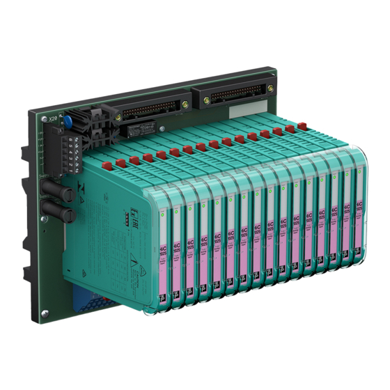
- Page 1 PROCESS AUTOMATION MANUAL H-System Isolated Barriers and Termination Boards for HIMA ISO9001...
- Page 2 H-System – Isolated Barriers and Termination Boards for HIMA With regard to the supply of products, the current issue of the following document is applicable: The General Terms of Delivery for Products and Services of the Electrical Industry, published by the Central Association of the Electrical Industry (Zentralverband Elektrotechnik und Elektroindustrie (ZVEI) e.V.) in its most recent...
-
Page 3: Table Of Contents
H-System – Isolated Barriers and Termination Boards for HIMA Content 1 Introduction........4 1.1 Contents . -
Page 4: Introduction
H-System – Isolated Barriers and Termination Boards for HIMA Introduction Introduction Contents This document contains information that you need in order to use your product throughout the applicable stages of the product life cycle. These can include the following: • Product identification •... -
Page 5: Target Group, Personnel
H-System – Isolated Barriers and Termination Boards for HIMA Introduction Target Group, Personnel Responsibility for planning, assembly, commissioning, operation, maintenance, and dismounting lies with the plant operator. Only appropriately trained and qualified personnel may carry out mounting, installation, commissioning, operation, maintenance, and dismounting of the product. - Page 6 H-System – Isolated Barriers and Termination Boards for HIMA Introduction Informative Symbols Note! This symbol brings important information to your attention. Action This symbol indicates a paragraph with instructions. You are prompted to perform an action or a sequence of actions.
-
Page 7: Product Specifications
The H-System isolated barriers are mounted on termination boards. Pre-wiring is possible on termination boards. To close the signal circuit, the isolated barriers are simply plugged in. -
Page 8: System Components
• HiC devices with a width of 12.5 mm • HiD devices with a width of 18 mm Both versions cover all functions and the interoperability of the H-System. The pin assignment and terminal designations are consistent for all termination boards. - Page 9 H-System – Isolated Barriers and Termination Boards for HIMA Product Specifications HiD Device Housing STATUS FAULT CH 2 CH 1 2872 Figure 2.3 HiD device housing (18 mm) Used for high channel density • Compact 18 mm housing • Highest channel density on the market •...
- Page 10 H-System – Isolated Barriers and Termination Boards for HIMA Product Specifications 2.2.2 Termination Boards Termination boards form the wiring level for field and control signals. The isolated barriers are mounted on termination boards. The isolated barriers are connected with the field and control side via the termination boards. Once the isolated barrier is mounted, the signal circuit between the field and control side is closed.
- Page 11 H-System – Isolated Barriers and Termination Boards for HIMA Product Specifications 2.2.3 Accessories Label carriers for Termination Boards The termination boards can be fitted with a label carrier for individual identification. Figure 2.5 Label carrier for termination boards Label carrier HiALC-HiCT*-SET-*** for HiC termination boards...
- Page 12 H-System – Isolated Barriers and Termination Boards for HIMA Product Specifications Application example The following diagram shows a typical example of an application with a Fault Indication Board and HART Communication Board. HART1 HART2 PWR1 PWR2 FAULT Field Figure 2.7...
-
Page 13: Connection Options
H-System – Isolated Barriers and Termination Boards for HIMA Product Specifications Connection Options A variety of termination boards is available with different methods of connecting to the field and control side. Please refer to the documentation for the respective device for the specific connection layout. - Page 14 H-System – Isolated Barriers and Termination Boards for HIMA Product Specifications Connecting the Control Side The termination board is connected on the control side via the HIMA system connector. Figure 2.10 Connection via HIMA system connector, 96-pin In the case of a signal splitter application, you can connect the termination board via spring terminals.
- Page 15 H-System – Isolated Barriers and Termination Boards for HIMA Product Specifications Connecting the HART Communication Connect the HART communication via HART multiplexer as follows: HART Plugs Figure 2.12 Connection via control-side HART plugs HART Multiplexers Figure 2.13 HART multiplexer connection Note! For more information see the corresponding datasheets.
-
Page 16: Color Coding Of The Isolated Barriers
H-System – Isolated Barriers and Termination Boards for HIMA Product Specifications Color Coding of the Isolated Barriers The color coding of the devices has the following meaning: FAULT STATUS STATUS/ STATUS/ FAULT FAULT FAULT 2821 2841 2873 2025 2081 2031 PROG Figure 2.14... -
Page 17: Status Indicators With Leds
H-System – Isolated Barriers and Termination Boards for HIMA Product Specifications Status Indicators with LEDs LEDs are often used on isolators to indicate different statuses (e. g. for power supply, device failure, status messages, binary switching states). Standard LED colors are assigned to the status display according to NAMUR NE44. -
Page 18: Status Indicators Of Termination Boards
H-System – Isolated Barriers and Termination Boards for HIMA Product Specifications OUT CHK PWR Figure 2.15 Example status indicators Yellow LED "OUT" Switching state of the output Red LED "CHK" Lead breakage and short circuit status indicator Green LED "PWR"... - Page 19 H-System – Isolated Barriers and Termination Boards for HIMA Product Specifications Field FAULT PWR2 PWR1 HART2 HART1 Figure 2.16 Example status indicators Green LED "PWR1" Status indicator power supply I Green LED "PWR2" Status indicator power supply II Red LED "FAULT"...
-
Page 20: Label Carriers
H-System – Isolated Barriers and Termination Boards for HIMA Product Specifications Label Carriers The isolated barriers are fitted with a label carrier ex works for individual identification. Figure 2.17 Label carrier on the front Label carrier on HiC devices for 35 mm x 10.5 mm labels... -
Page 21: Installation
H-System – Isolated Barriers and Termination Boards for HIMA Installation Installation DIN Mounting Rail The devices are mounted on a 35 mm DIN mounting rail according to EN 60715. Figure 3.1 Example: DIN mounting rail UPR-MR (35 mm x 15 mm) Mounting 3.2.1... - Page 22 H-System – Isolated Barriers and Termination Boards for HIMA Installation Mounting the Termination Boards The termination boards are mounted on the 35 mm DIN mounting rail. The DIN mounting rail runs centrally below the termination board. 1. Clip the termination board (2) onto the DIN mounting rail (1).
- Page 23 H-System – Isolated Barriers and Termination Boards for HIMA Installation Vertical and Horizontal Mounting Both mounting options are possible. Unrestricted operation is possible across the entire temperature range of the system in each mounting direction. Vertical mounting Horizontal mounting Figure 3.4...
- Page 24 H-System – Isolated Barriers and Termination Boards for HIMA Installation 3.2.2 Isolated Barriers Mounting Mounting the Isolated Barriers on the Termination Board 1. Push the Quick Lok bar (1) into the upper position. 2. Center the pins (2) above the contact elements of the termination board. Note the connection direction of the device.
-
Page 25: Connection
H-System – Isolated Barriers and Termination Boards for HIMA Installation Connection Danger! Danger to life from electric shock Absent or insufficient insulation can result in electric shock. Only connect supplies that provide protection against electric shock (e. g. SELV or PELV). -
Page 26: Device Parameterization
H-System – Isolated Barriers and Termination Boards for HIMA Installation Connecting Circuits 1. Connect the field circuit. 2. Connect the control circuit. 3. Connect the power supply. Note! For more information see the corresponding datasheets. Device Parameterization The devices are parameterized using DIP switches. -
Page 27: Operation
Fault Output Several H-System isolators monitor the field leads for lead breakage and short circuits. This means that faults are immediately identified in the system, and that lead faults are not interpreted as a signal. - Page 28 H-System – Isolated Barriers and Termination Boards for HIMA Operation Line Fault Transparency (LFT) If the device has a signal output with line fault transparency, the fault message can be transmitted on the signal lead. This saves additional wiring and delivers channel-selective fault messages.
-
Page 29: Current And Voltage Standard Signals
H-System – Isolated Barriers and Termination Boards for HIMA Operation Current and Voltage Standard Signals The following signals have established themselves as the standard: • the 0/4 mA to 20 mA current signal • the 0/2 V to 10 V voltage signal The 0/1 V to 5 V voltage signal is also occasionally encountered in addition to the 0/2 V to 10 V voltage signal. -
Page 30: Dismounting, Maintenance, And Repair
H-System – Isolated Barriers and Termination Boards for HIMA Dismounting, Maintenance, and Repair Dismounting, Maintenance, and Repair Danger! Danger to life from using damaged or repaired devices. Using a defective or repaired device can compromise its function and its electrical safety. -
Page 31: Termination Board Dismounting
H-System – Isolated Barriers and Termination Boards for HIMA Dismounting, Maintenance, and Repair Termination Board Dismounting Warning! Risk of short circuit Working on live parts can cause injuries and can compromise the function and the electrical safety of the device. -
Page 32: Technical Specifications
H-System – Isolated Barriers and Termination Boards for HIMA Technical Specifications Technical Specifications Technical Data 6.1.1 Electrical Data Power Supply to the Isolated Barriers • HiC devices: 19.6 V DC to 30 V DC • HiD devices: 20.4 V DC to 30 V DC The voltage drop on the termination board via the decoupling diodes must be considered. - Page 33 H-System – Isolated Barriers and Termination Boards for HIMA Technical Specifications 6.1.2 Conformity General • Isolated barriers with explosion protection, preferably Ex ia IIC/Class I, Div. 1, international approvals • EMV according to • EN 61326-1 • EN 61326-3-2, only for devices with SIL rating, where the data sheet mentions this standard.
- Page 34 H-System – Isolated Barriers and Termination Boards for HIMA Technical Specifications 6.1.3 Ambient Conditions Ambient Temperature • -20 °C to 60 °C (-4 °F to 140 °F), exceptions see data sheets Storage Temperature • -40 °C to 85 °C (-40 °F to 185 °F), exceptions see data sheets Reference Conditions for Adjustment •...
- Page 35 H-System – Isolated Barriers and Termination Boards for HIMA Technical Specifications Connection to Termination Board • Field side: • Spring terminals: 0.25 ... 1.5 mm (24 ... 16 AWG) • Power supply and fault indication output: • Spring terminals: 0.25 ... 1.5 mm (24 ...
-
Page 36: Model Number Description
H-System – Isolated Barriers and Termination Boards for HIMA Technical Specifications Model Number Description Model Number Description Isolated Barriers Special functions, if available ES Version with increased safety HC Versions for long field wiring Version with DCS specific line fault transparency (LFT) -
Page 37: Pin Assignment And Device Coding
H-System – Isolated Barriers and Termination Boards for HIMA Technical Specifications Pin Assignment and Device Coding The isolated barriers are coded in accordance with their function. Warning! Possible Device Failure Changes in the pin configuration may lead to device failure. To polarize the device in accordance with its safety parameters, the pins are shortened at the factory. - Page 38 H-System – Isolated Barriers and Termination Boards for HIMA Technical Specifications Termination board Isolated barrier Type Top view Bottom view Safe area Hazardous Hazardous Safe area area area HiC2027, HiC2877 HiC2031HC – – HiC2081 HiC2077 HiC2065, HiC2068 Empty position + + +...
- Page 39 H-System – Isolated Barriers and Termination Boards for HIMA Technical Specifications Device Coding of HiD Devices and HiD Termination Boards Termination board Isolated barrier Type Top view Bottom view Safe area Hazardous Hazardous Safe area area area HiD2000 all non-intrinsically safe devices –...
- Page 40 H-System – Isolated Barriers and Termination Boards for HIMA Technical Specifications Termination board Isolated barrier Type Top view Bottom view Safe area Hazardous Hazardous Safe area area area HiD2012 HiD2891 – – HiD2862 Empty position Insert polarizing pin Pin to be trimmed...
-
Page 41: Dimensions
H-System – Isolated Barriers and Termination Boards for HIMA Technical Specifications Dimensions 6.4.1 Housing Designs for H-System Isolated Barriers HiC Device Housings 128 mm (5.04") 12,5 mm (0.5") Figure 6.1 HiD Device Housings 128 mm (5.04") 18 mm (0.71") Figure 6.2... - Page 42 H-System – Isolated Barriers and Termination Boards for HIMA Technical Specifications 6.4.2 Housing Types Termination Boards HiC Termination Boards for 16 Modules 253 mm (9.96 inch) 266 mm (10.47 inch) 163 mm (6.42 inch) Figure 6.3 HiC Termination Boards for 32 Modules 253 mm (9.96 inch)
- Page 43 H-System – Isolated Barriers and Termination Boards for HIMA Technical Specifications HiD Termination Board for 16 Modules 253 mm (9.96 inch) 163 mm (6.42 inch) 300 mm (11.81 inch) Figure 6.5 HiD Termination Board for 16 Modules, Housing Version 253 mm (9.96 inch) 350 mm (13.77 inch)
- Page 44 PROCESS AUTOMATION – PROTECTING YOUR PROCESS Worldwide Headquarters Pepperl+Fuchs GmbH 68307 Mannheim · Germany Tel. +49 621 776-0 E-mail: info@de.pepperl-fuchs.com For the Pepperl+Fuchs representative closest to you check www.pepperl-fuchs.com/contact www.pepperl-fuchs.com Subject to modifications Copyright PEPPERL+FUCHS • Printed in Germany DOCT-5301 11/2016...
Need help?
Do you have a question about the H-System and is the answer not in the manual?
Questions and answers