Table of Contents
Advertisement
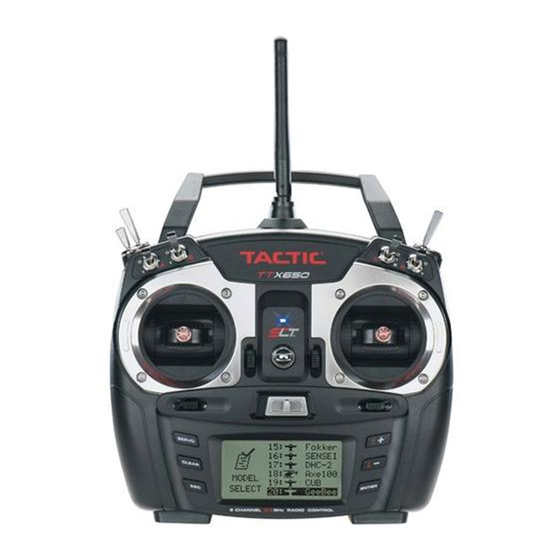
2.4GHz 6-CHANNEL COMPUTER RADIO
INSTRUCTION MANUAL
Tactic's TTX650 computer transmitter uses the advanced 2.4GHz spread spectrum SLT "Secure Link Technology"
protocol for solid, interference-free control of R/C models. Ball-bearing gimbals, a wireless trainer system, 20
model memories, and advanced programming options are just a few of the benefits which can be used on models
of all sizes. Tactic 2.4GHz transmitters are compatible only with Tactic brand receivers and those utilizing the SLT
protocol.
For safe operation and best results, it's strongly recommended to read this manual in its entirety
before use! Also read and understand the instructions included with the model. Damage resulting
from misuse or modification will void your warranty.
INDEX
Charge Jack and Rechargeable Batteries
Stick Tension and Throttle Ratchet
Servo Set (reverse, sub-trim, travel limits)
xx
xx
xx
xx
xx
xx
xx
xx
xx
xx
xx
xx
xx
xx
xx
xx
xx
xx
xx
xx
xx
xx
xx
xx
xx
xx
xx
xx
xx
xx
xx
1
Advertisement
Table of Contents

Related Manuals for Tactic TTX650


Summary of Contents for Tactic TTX650
-
Page 1: Table Of Contents
R/C models. Ball-bearing gimbals, a wireless trainer system, 20 model memories, and advanced programming options are just a few of the benefits which can be used on models of all sizes. Tactic 2.4GHz transmitters are compatible only with Tactic brand receivers and those utilizing the SLT protocol. - Page 2 FAILSAFE FUNCTION WIRELESS TRAINER RANGE TEST FIRMWARE UPGRADES WARNING INDICATIONS SYSTEM CHECK AND OPERATION FLYING THE AIRCRAFT IMPORTANT WARNINGS AND PRECAUTIONS TTX650 SPECIFICATIONS TROUBLESHOOTING SAFETY GUIDE ACCESSORIES FCC STATEMENT WARRANTY INFORMATION ** large glamour picture with callouts neck strap eyelet...
-
Page 3: Slt Technology, Tx-R, And Compatible Receivers
INPUT POWER: Four 1.5V "AA" alkaline cells (included) or 1.2V "AA" NiCd or NiMH cells supply power to the TTX650. Do not mix cell types, or old and new cells, etc. Slide open the battery door to find the four "AA" cell battery holder. -
Page 4: Power Led
NiCd or NiMH batteries (charger not included). Do not try to recharge alkaline batteries. Charge adapters for Futaba TTX650 CHARGE JACK brand transmitters are compatible, with the center pin being positive polarity. The Tx power switch must be in the OFF position to recharge batteries. -
Page 5: Digital Stick Trims
WARNING! Failure to follow these instructions for separating and re-assembling the Tx case can result in permanent damage to the transmitter, and void the warranty. Contact Hobby Services if you do not feel comfortable that you can safely and accurately perform these steps. ALWAYS disconnect and remove the batteries from the battery compartment FIRST. -
Page 6: Antenna
MENUS The TTX650 has three types of menus. The SYSTEM SETUP menu allows for setting basic operational functions for the radio itself. Selecting and managing the model memories, configuring the radio for the structure of the airplane or helicopter, etc. -
Page 7: Stick Mode
Pressing ← or → can move the cursor freely. Repeat as necessary for up to 8 characters. Pressing CLEAR will move the cursor back one space and erase the character in that space. Press ESC when finished. STICK MODE: The TTX650 is factory set to Mode 2 configuration, but can be changed to... -
Page 8: Battery Alarm
BATTERY ALARM: An alarm will sound and the display will show "LOW BATTERY" when the Tx battery's voltage drops to the level shown in this setting. Do NOT set this value too low, as the radio could lose power very rapidly as the battery nears full discharge and cause a loss of control of the model. -
Page 9: Wing Type
Reset: To change the parameters of any single memory except model type and model name use this reset function. Enter this screen, move the cursor over the memory to reset and press ENTER. Select "NO" to cancel or "YES" to proceed with the reset, and press ENTER. The display will then return to the home screen. Erase: Use the erase function to completely clear all settings (including model type and name) in any single memory to factory default settings. -
Page 10: Channel Assignments
plug positions at the Rx for the delta wing mix. If the delta wing option is selected, and the "FLAP" option below is set to 2AI1FL, the elevator channel will mix 100% to the aileron channel. AIRPLANE DELTA WING 2AIL 2AIL/1FLAP ELEVON1 ELEVON1... -
Page 11: Warnings
TRAINER: The process of binding transmitters for training purposes is explained on page xx. When in training mode with the TTX650 being used by the teacher, this radio can allow the teacher to transfer control of all or only certain channels to the student if desired. -
Page 12: Ch5 And Ch6 Set
Sub-trim: Finely adjusts a channel's center position. Be aware that extreme adjustments of sub-trim could possibly result in servo binding if the servo's output arm moves too far in the model. This is available for all channels. Travel limits: Sets the maximum travel limits for each channel. Limits can be set for each side of center. If two channels are mixed, adjusting the travel limits of each individual channel may be necessary to adjust the travel limits for the entire mix. -
Page 13: Throttle Curve
The display will show a graphic representing the switch, and the different control positions of the switch as shown here (0, 1, and 2). The default position for "0" will always be in the down direction. The control positions of the switch can be assigned to fit personal preference. -
Page 14: Throttle Cut
Pressing ↑+ or ↓- will adjust the vertical position of curve at this exact point. Adjust as desired. Repeat these steps to set points 2, 3, and 4 on the graph as desired. A point for "H" is not marked on the graph, but is the right-most end of the curve line. -
Page 15: Aileron Mixer
of one aileron is at a lower or higher rate than the opposite aileron. Certain applications may require a reduction in the aileron differential rate when an airbrake is applied. This feature is useful for glider and/or sailplane applications which use other settings to achieve "butterfly" or "crow" functionality. Enter the DIFFERENTIAL function. -
Page 16: Flap Mixer
The method for making adjustments in this screen is the same as described above. In the WING TYPE menu, if the FLAP selection is set to 2AI1FL and the TAIL selection is set to Delta, the elevator-to-aileron mixture will automatically be fixed to 100%. If the 1AI1FL wing type is selected the elevator can be mixed to the flaps. -
Page 17: Programmable Mixer
When the 2AIL1FL wing type is selected the brake can be mixed with each the elevator, aileron, or flaps. Adjust each mix percentage as needed. Select a switch to turn the mix on/off.. PROGRAMMABLE MIXER: Up to four programmable mixes can be set, with one channel being mixed to any one or more channels. -
Page 18: Model Setup Menu - Helicopters
The "START/STOP" screen should show. Moving the stick up or down will show changes to the "THROTTLE" position value. The "START/STOP" value shows the trip point where starting and stopping the timer will occur. Move the stick to the position where the timer's trip point and press ENTER. The position value for START/STOP should now match that for THROTTLE. -
Page 19: Throttle Cut
Setting of the SERVO SET, DUAL-RATES, EXPONENTIAL, RF OUTPUT, and TIMER functions is the same as described for airplanes on pages xx - xx. However, if using a helicopter which has CCPM mixing, read the SWASH TYPE section on the previous page before adjusting the reversing and travel limits settings. THROTTLE CUT: Allows the throttle channel's output to be quickly moved to a user-defined position by flipping a switch. -
Page 20: Pitch Curve
The idle-up function is used to optimize the throttle position for all flight envelopes including aerobatic flight. By default the TTX650 assigns switch E as the idle-up control switch. This switch incorporates one "normal" and two "up" functions within the three positions of the switch. -
Page 21: Gyro Mixing
GYRO MIXING: This function is for setting and switching the sensitivity of an optional gyro. Enter this screen. To make the gyro mixing active at all times do NOT assign a switch at the CTRL line. Press ENTER to highlight the normal mixing rate, and press ↑+ or ↓- to find the desired value. -
Page 22: Programmable Mixer
1–6 above. FAILSAFE FUNCTION The failsafe function is not controlled by the TTX650 transmitter itself, but rather by the Tactic receiver. Tactic's stand-alone 2.4GHz receivers have a failsafe feature which engages in the event that the signal from the Tx somehow becomes interrupted. -
Page 23: Wireless Trainer
Two Tactic brand transmitters with trainer capabilities can communicate with each other by wireless means for teaching a student how to fly (no trainer jack - no cable required!). The TTX650 can be configured for wireless trainer function with any other Tactic brand transmitter, but is not compatible with wireless trainer systems in other brand transmitters. -
Page 24: Range Test
RANGE TEST: Before each flight make sure to check the operating range of the Tx / Rx set. The TTX650 includes a function that automatically reduces its output power to prevent having to walk a long distance to check the... -
Page 25: Warning Indications
Pressing ENTER any time during countdown will stop the timer. FIRMWARE UPDATES A 3-pin socket above the charge jack on the left side of the radio is used for updating the TTX650's operating firmware. An optional Tactic TTX650 USB Firmware Interface (part number TACJ2651) is required. The software and suitable driver required for the download are free and found at http://tacticrc.com/tacj2650.html. -
Page 26: System Check And Operation
transmitter's Rf section is turned ON, the Tx will automatically shut down 120 seconds after this message shows. If the Rf section is turned OFF, the Tx will shut down 60 seconds after this message shows. SYSTEM CHECK AND OPERATION WARNING! Always make sure that power is applied to the transmitter BEFORE applying power to the receiver and servos, and the Tx throttle stick is at minimum (idle) position. -
Page 27: Important Warnings And Precautions
CA glue, etc. could permanently damage plastic parts of the radio system. * If rechargeable batteries were installed in the transmitter, remove the batteries before placing the radio in long- term storage. TTX650 SPECIFICATIONS Model types: airplane and helicopter... -
Page 28: Troubleshooting
Tx to Rx in the transmitter's programming. Contact Hobby Services for further details. WIRELESS TRAINING FUNCTION NOT BINDING: Check to see that another Tactic 2.4GHz system is not on in your area. The teacher's and student's transmitters were not powered in the proper sequence or are positioned too far from each other. -
Page 29: Accessories
1-YEAR LIMITED WARRANTY - *U.S.A. and Canada Only Tactic warrants this product to be free from defects in materials and workmanship for a period of one (1) year from the date of purchase. During that period, Tactic will, at its option, repair or replace without service charge any product deemed defective due to those causes. - Page 30 This warranty gives you specific rights. You may have other rights, which vary from state to state. For service on your Tactic product, send it postpaid and insured to: HOBBY SERVICES 3002 N.
Need help?
Do you have a question about the TTX650 and is the answer not in the manual?
Questions and answers