Advertisement
Quick Links
INSTALLATION AND MAINTENANCE INSTRUCTIONS
CR-6 Six Relay Control Module
SPECIFICATIONS
Normal Operating Voltage:
Stand-By Current:
Alarm Current:
Temperature Range:
Humidity:
Dimensions:
Accessories:
Wire Gauge:
Relay Current:
RELAY CONTACT RATINGS:
CURRENT RATING
2 A
3 A
2 A
0.46 A
0.7 A
0.9 A
0.5 A
0.3 A
All relay switch contacts are shipped in the standby state (open) state, but may have transferred to the activated (closed) state during shipping. To ensure that
the switch contacts are in their correct state, modules must be made to communicate with the panel before connecting circuits controlled by the module.
BEFORE INSTALLING
This information is included as a quick reference installation guide. If the
modules will be installed in an existing operational system, inform the op-
erator and local authority that the system will be temporarily out of service.
Disconnect the power to the control panel before installing the modules. This
system contains static sensitive components. Always ground yourself with a
proper wrist strap before handling any circuits so that static charges are re-
moved from the body. The housing cabinet should be metallic and suitably
grounded.
NOTICE: This manual should be left with the owner/user of this equipment.
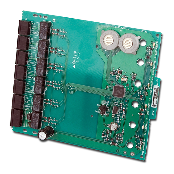
GENERAL DESCRIPTION
The CR-6 Six Relay Control Module is intended for use in an intelligent alarm
system. Each module is intended for Form-C switching applications, which do
not require wiring supervision for the load circuit. A single isolated set of dry
relay contacts is provided for each module, which is capable of being wired
for either normally open or normally closed for each operation. Each module
has its own address. A pair of rotary code switches is used to set the address
of the first module from 01 to 94. The remaining modules are automatically as-
signed to the next five higher addresses. Provisions are included for disabling
a maximum of three unused modules to release the addresses to be used else-
where. Each CR-6 module also has panel controlled green LED indicators. The
panel can cause the LEDs to blink, latch on, or latch off.
15-32 VDC
1.90 mA @ 24V
32 mA (assumes all six relays have been switched once and all six LEDs solid on)
32°F to 120°F (0°C to 49°C)
10 to 93% Non-condensing
6.8˝H × 5.8˝W × 1.0˝D
BB-2 Cabinet; BB-6 Cabinet; CH-6 Chassis
12-18 AWG
30 mA/Relay Pulse (15.6 mS pulse duration) pulse under panel control
MAXIMUM VOLTAGE
25 VAC
30 VDC
30 VDC
30 VDC
70.7 VAC
125 VDC
125 VAC
125 VAC
WARNING
LOAD DESCRIPTION
PF = 0.35
Resistive
Resistive
(L/R = 20ms)
PF = 0.35
Resistive
PF = 0.75
PF = 0.35
CONTENTS INCLUDE:
(6) 1 x 3 Terminal Blocks
(1) 1 x 4 Terminal Blocks
(2) 1¼ ˝ (32mm) Stand offs
(4) Machine Screws
(1) Shunt (NOTE: For the disable position, not more than one shunt shall be
installed at the same time)
(2) Nuts
COMPATIBILITY REQUIREMENTS
To ensure proper operation, this module shall be connected to a compatible
control panel only.
COMPONENTS
Following are descriptions of the CR-6 mounting frameworks. There are two
mounting options for CR-6 modules:
• Up to six CR-6 modules can be installed on a CH-6 in a BB-6 cabinet
• One or two CR-6 modules can be installed in a BB-2 cabinet
Chassis
The CH-6 chassis is used to mount CR-6 modules in a BB-6 cabinet. It accom-
modates up to six CR-6 modules in a single cabinet row three modules wide
and two modules deep.
1
3825 Ohio Avenue, St. Charles, Illinois 60174
1-800-SENSOR2, FAX: 630-377-6495
www.systemsensor.com
APPLICATION
Non-coded
Non-coded
Coded
Non-coded
Non-coded
Non-coded
Non-coded
Non-coded
I56-1798-012
03-11
Advertisement

Related Manuals for System Sensor CR-6


Summary of Contents for System Sensor CR-6
- Page 1 • Up to six CR-6 modules can be installed on a CH-6 in a BB-6 cabinet for either normally open or normally closed for each operation. Each module •...
- Page 2 Cabinets A BB-6 cabinet will house the CH-6 chassis with up to six CR-6 modules in- stalled on it. The BB-2 cabinet houses one or two CR-6 modules on the internal chassis that is part of the cabinet.
- Page 3 Disable is placed on “two” and the base address switch is set to 28, the modules will be assigned to 28, 29, 30 and 31. Step 1: Insert the bottom edge of the CR-6 module down into a rear slot of the chassis.
- Page 4 C205-01 6.8" NOTES: • The relay contacts on the CR-6 may be connected to either a power- limited or non power-limited source, this wiring must remain separated by at least 1/4˝ (6.35 mm) from all power-limited wiring. • Power-limited circuits must employ type FPL, FPLR, or FPLP cable as required by Article 760 of the NEC.
Need help?
Do you have a question about the CR-6 and is the answer not in the manual?
Questions and answers