Table of Contents
Advertisement
Quick Links
INSTALLATION AND MAINTENANCE INSTRUCTIONS
M500M Monitor Module
SpECIfICATIONS
Normal Operating Voltage:
Maximum Current Draw:
Average Operating Current:
EOL Resistance:
Maximum IDC wiring resistance:
Maximum IDC Voltage:
Maximum IDC Current:
Temperature Range:
Humidity:
Dimensions:
Accessories:
BEfORE INSTALLINg
This information is included as a quick reference installation guide. Refer to
the control panel installation manual for detailed system information. If the
modules will be installed in an existing operational system, inform the opera-
tor and local authority that the system will be temporarily out of service. Dis-
connect power to the control panel before installing the modules.
NOTICE: This manual should be left with the owner/user of this equipment.
gENERAL DESCRIpTION
The M500M Monitor Module is intended for use in intelligent, two-wire sys-
tems, where the individual address of each module is selected using the built-
in rotary decade switches. It provides either a 2-wire or 4-wire fault tolerant
initiating circuit for normally open contact fire alarm, supervisory, or security
devices. The module has a panel controlled LED indicator.
COMpATIBILITy REqUIREMENTS
To ensure proper operation, these modules shall be connected to listed com-
patible system control panels only.
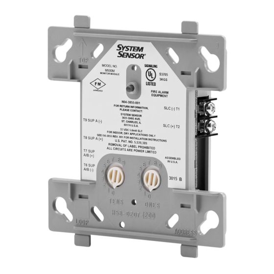
fIgURE 1. CONTROLS AND INDICATORS:
SS-460-004
15 to 32 VDC
5.0mA (LED on)
350 μA, 1 communication every 5 seconds, 47k EOL
47K Ohms
40 Ohms
11 Volts
400μA
32˚F to 120˚F (0˚C to 49˚C)
10% to 93% Non-condensing
4
1
/
˝ H x 4˝ W x 1
1
/
˝ D (Mounts to a 4˝ square by 2
2
4
SMB500 Electrical Box
C0917-01
firealarmresources.com
1
/
˝ deep box.)
8
MOUNTINg
The M500M mounts directly to 4-inch square electrical boxes (see Figure 2).
The box must have a minimum depth of 2
cal boxes (SMB500) are available from System Sensor.
fIgURE 2. MODULE MOUNTINg:
WIRINg
NOTE: All wiring must conform to applicable local codes, ordinances, and
regulations. This module is intended for power limited wiring only.
1.
Install module wiring in accordance with the job drawings and appropri-
ate wiring diagrams.
2.
Set the address on the module per job drawings.
3.
Secure module to electrical box (supplied by installer), as shown in
Figure 2.
1
3825 Ohio Avenue, St. Charles, Illinois 60174
1-800-SENSOR2, FAX: 630-377-6495
www.systemsensor.com
1
/
inches. Surface mounted electri-
8
ISOLATED
QUADRANT
I56-3855-001
C1044-00
Advertisement
Table of Contents

Related Manuals for System Sensor M500M


Summary of Contents for System Sensor M500M
- Page 1 SMB500 Electrical Box MOUNTINg BEfORE INSTALLINg The M500M mounts directly to 4-inch square electrical boxes (see Figure 2). This information is included as a quick reference installation guide. Refer to the control panel installation manual for detailed system information. If the The box must have a minimum depth of 2 inches.
- Page 2 C0919-03 ThREE-yEAR LIMITED WARRANTy System Sensor warrants its enclosed product to be free from defects in materials and #__________, 3825 Ohio Avenue, St. Charles, IL 60174. Please include a note describing workmanship under normal use and service for a period of three years from date of the malfunction and suspected cause of failure.
Need help?
Do you have a question about the M500M and is the answer not in the manual?
Questions and answers