Table of Contents
Advertisement
Quick Links
INSTALLATION
AND
Series
CRRS-MODA Reversing Relay/Synchronization Module
Specifications
Operating Voltage Range:
Maximum Operating Current:
Relay Contacts:
Operating Temperature Range:
Operating Humidity Range:
Dimensions:
Wire connections:
General Description
The CRRS-MODA polarity reversing relay/synchronization
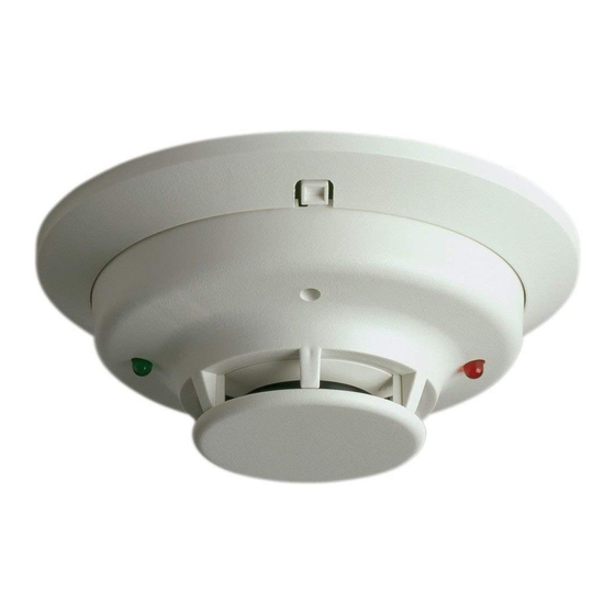
module is intended for use with 2-wire and 4-wire i 3
series detectors equipped with a built-in sounder, models
C2WTA-BA, C4WTA-BA, C4WTAR-BA, and C4WITAR-
BA. It is designed to allow all the detectors in the same
loop to sound when one of the detectors goes into alarm,
and to synchronize their audible output. The CRRS-MODA
also allows the silencing of the detector sounders from the
alarm control panel.
The CRRS-MODA may be used with an alarm zone that
provides coded output for fire and continuous output for
burglary. By default the CRRS-MODA's switch is set to
"off". Therefore, the CRRS-MODA will only trigger when
the alarm output is coded. In this manner, smoke detec-
tors will only sound from the result of a fire, and not from
a burglary alarm. In this mode, the detectors will provide a
synchronized, coded output.
The CRRS-MODA can also be set to only trigger on con-
tinuous alarm zone signals by selecting the switch to "on".
In this mode, the detectors will provide a synchronized,
coded output.
NOTICE: This manual shall be left with the owner/user of
this equipment.
NOTE: If your panel configuration does not match any
of the provided wiring diagrams, please contact System
Sensor technical services at 1-800-SENSOR2 for assis-
tance.
Installation
Mount module in a 4" square electrical box adjacent to the
control panel.
D500-44-00
MAINTENANCE
INSTRUCTIONS
8.5 to 35 VDC
25mA
2A at 35 VDC
32° to 131° F (0° to 55° C)
5% to 85% non-condensing
2
⁄
" x 2
⁄
1
1
2
2
18 AWG stranded, tinned, 16" long
6581 Kitimat Rd. Unit #6 Mississauga, Ontario L5N 3T5
NOTE: In an alarm condition, a wiring-fault
trouble state may also register at the panel
when the CRRS-MODA is used.
" x 1"
When calculating total current draw of the control panel,
remember to add current consumption (25mA) for the
polarity reversal relay module (CRRS-MODA).
IMPORTANT: If the fire alarm output signal is coded, set
the switch on the CRRS-MODA to "OFF". If the fire alarm
output signal is continuous, set the switch to "ON".
Wiring
IMPORTANT: All polarities must be observed!
1. Connect the CRRS-MODA module trigger wire to the
fire alarm output terminals.
A. Alarm/Bell output: (Figures 1 and 2)
Connect the purple wire to the Alarm or Bell output.
B. Alarm relay, normally open contact: (Figures 3 and 4)
1. Connect one end of the alarm relay contact output
to positive auxiliary or detector power fire alarm
output.
2. Connect the purple wire to the other end of the
alarm relay contact output.
2. Connect the red and black wires to the panel auxiliary
or detector power (red to positive, black to negative).
3. 2-wire models
Connect the yellow and orange wires to the panel initiat-
ing circuit (yellow to positive, orange to negative).
4-wire models
Connect the yellow and orange wires to the panel detec-
tor power circuit (yellow to positive, orange to negative).
4. 2-wire models
Connect the brown and white wires to the smoke detec-
tor power supply input (brown to positive, white to nega-
tive).
4-wire models
Connect the brown and white wires to the smoke detec-
tor power circuit (brown to positive, white to negative).
1
1-800-SENSOR2, FAX: 905-812-0772
www.systemsensor.ca
WARNING
I56-2373-000
Advertisement
Table of Contents

Subscribe to Our Youtube Channel
Related Manuals for System Sensor i3 Series


Summary of Contents for System Sensor i3 Series
- Page 1 INSTALLATION MAINTENANCE INSTRUCTIONS 6581 Kitimat Rd. Unit #6 Mississauga, Ontario L5N 3T5 Series 1-800-SENSOR2, FAX: 905-812-0772 www.systemsensor.ca CRRS-MODA Reversing Relay/Synchronization Module Specifications NOTE: In an alarm condition, a wiring-fault Operating Voltage Range: 8.5 to 35 VDC trouble state may also register at the panel Maximum Operating Current: 25mA when the CRRS-MODA is used.
- Page 2 NOTE: If your panel configuration does not match any of the following wiring diagrams, please contact System Sensor technical services at 1-800-SENSOR2 for assistance. Figure 1. 2-Wire system triggered from alarm/bell output: ULC LISTED ALARM CONTROL PANEL PURPLE BROWN 1 + IN...
- Page 3 Figure 3. 2-Wire system triggered from alarm relay contact: ULC LISTED ALARM CONTROL PANEL ALARM PURPLE RELAY (NO Contact) BROWN 1 + IN 1 + IN OUT+ YELLOW 2–WIRE 2 + OUT 2 + OUT INITIATING DEVICE 3 - IN/OUT 3 - IN/OUT ORANGE –...
- Page 4 Three-Year Limited Warranty System Sensor warrants its enclosed relay module to be free from defects in mate- Mississauga ON, L5N 3T5. Please include a note describing the malfunction and rials and workmanship under normal use and service for a period of three years suspected cause of failure.
Need help?
Do you have a question about the i3 Series and is the answer not in the manual?
Questions and answers