Advertisement
INSTALLATION AND MAINTENANCE INSTRUCTIONS
M501MAP Monitor Module
SPECIFICATIONS
Nominal Operating Voltage:
Maximum Alarm Current:
Average Operating Current:
EOL Resistance:
Maximum IDC Wiring Resistance:
Maximum IDC Voltage:
Maximum IDC Current:
Temperature Range:
Humidity:
Dimensions:
Wire length:
UL864 listed
BEFORE INSTALLING
This information is included as a quick reference installation guide. Refer to
the control panel installation manual for detailed system information. If the
modules will be installed in an existing operational system, inform the opera-
tor and local authority that the system will be temporarily out of service. Dis-
connect power to the control panel before installing the modules.
NOTICE: This manual should be left with the owner/user of this equipment.
GENERAL DESCRIPTION
The M501MAP monitor module can be installed in a single gang junction box
directly behind the monitored unit. Its small size and light weight allow it to
be installed without rigid mounting (see Figure 1). The M501MAP is intended
for use in intelligent, two-wire systems where the individual address of each
module is selected using rotary decade switches. It provides a two-wire initiat-
ing circuit for normally open contact fire alarm and security devices.
COMPATIBILITY REQUIREMENTS
To ensure proper operation, these modules shall be connected to listed com-
patible system control panels only.
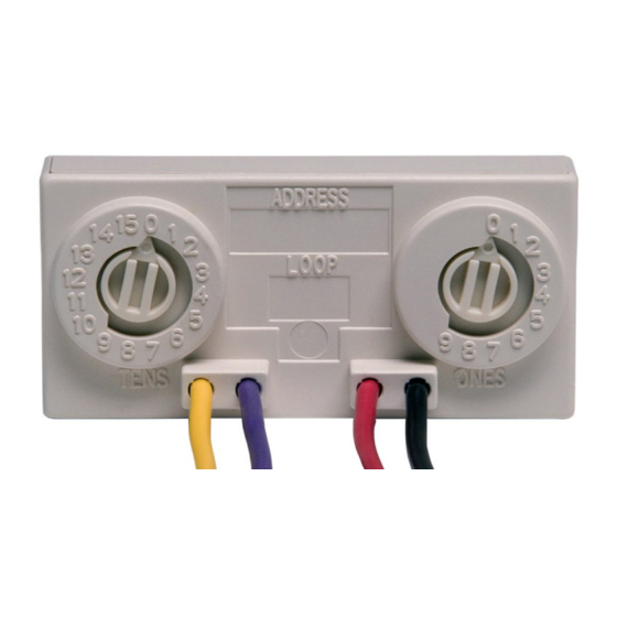
FIGURE 1. CONTROLS AND INDICATORS
15-32 VDC
600 uA
400 µA, 1 communication every 5 seconds, 47k EOL
47K Ohms
40 Ohms
11 Volts
400µA
32°F to 120°F (0°C to 49°C)
10% to 93% Non-condensing
1.3" H x 2.75" W x 0.65" D (3.33.02 mm H x 69.85 mm W x 16.51 mm D)
6" minimum (15.24 cm)
C0613-05
MOUNTING AND WIRING
NOTE: This module is intended to be wired and mounted without rigid con-
nections inside a standard electrical box. All wiring must conform to appli-
cable local codes, ordinances, and regulations.
1.
Connect the red (+) and black ( – ) wires to the positive and negative
loop power leads of the signaling line circuit.
2.
Connect the violet (+) and yellow ( – ) wires to a two-wire, normally
open initiating loop.
3.
Install the specified EOL resistor value to terminate the initiating loop.
4.
Set the address on the module per job drawings.
5.
Install the module in the desired mounting location.
FIGURE 2. TYPICAL 2-WIRE STYLE B INITIATING
CIRCUIT CONFIGURATION
UL LISTED
COMPATIBLE
CONTROL
SIGNAL LINE CIRCUIT (SLC)
PANEL
(+)
(–)
ALL WIRING
SHOWN IS
SUPERVISED AND
POWER LIMITED
1
3825 Ohio Avenue, St. Charles, Illinois 60174
1-800-SENSOR2, FAX: 630-377-6495
www.systemsensor.com
(–)
(+)
7 8
6 7 8 9
6
9 10
)
( +
)
( –
5
5
4
11
4
12
3
3
13
2
2
14
1
1
0
0
15
VIOLET
YELLOW
47k EOL
INCLUDED
(ELR-47k)
I56-6786-000
TO
NEXT
DEVICE
C0614-04
8/19/2020
Advertisement
Table of Contents

Related Manuals for System Sensor M501MAP


Summary of Contents for System Sensor M501MAP
- Page 1 GENERAL DESCRIPTION Set the address on the module per job drawings. The M501MAP monitor module can be installed in a single gang junction box directly behind the monitored unit. Its small size and light weight allow it to Install the module in the desired mounting location.
- Page 2 THREE-YEAR LIMITED WARRANTY System Sensor warrants its enclosed product to be free from defects in materials and TX 79936 USA. Please include a note describing the malfunction and suspected cause of workmanship under normal use and service for a period of three years from date of failure.
Need help?
Do you have a question about the M501MAP and is the answer not in the manual?
Questions and answers