Advertisement
Quick Links
INSTALLATION AND MAINTENANCE INSTRUCTIONS
MDL Module
For use with the following series models:
H12/24, HC12/24, MA12/24D, PA400, S12XX, S24XX, SC24XX, P12XX,
P24XX, PC24XX, SP2C24XX, SP2R24XX, SP2W24XX, DS2475XXX
Add suffix "W" for white models.
Refer to System Sensor product installation manuals
for model specifications.
Specifications
Voltage Range:
Maximum Load on Loop:
Current:
Operating Temperature:
Listings:
General Description
The MDL Module is designed to work with the SpectrAlert
series of horns, strobes, and horn/strobes to provide a
means of synchronizing the Temporal-coded horns, syn-
chronizing the one-second flash timing of the strobe, and
silencing the horns of the horn/strobe combination over a
two-wire circuit while leaving the strobes active.
NOTICE: This manual shall be left with the owner/user of
this equipment.
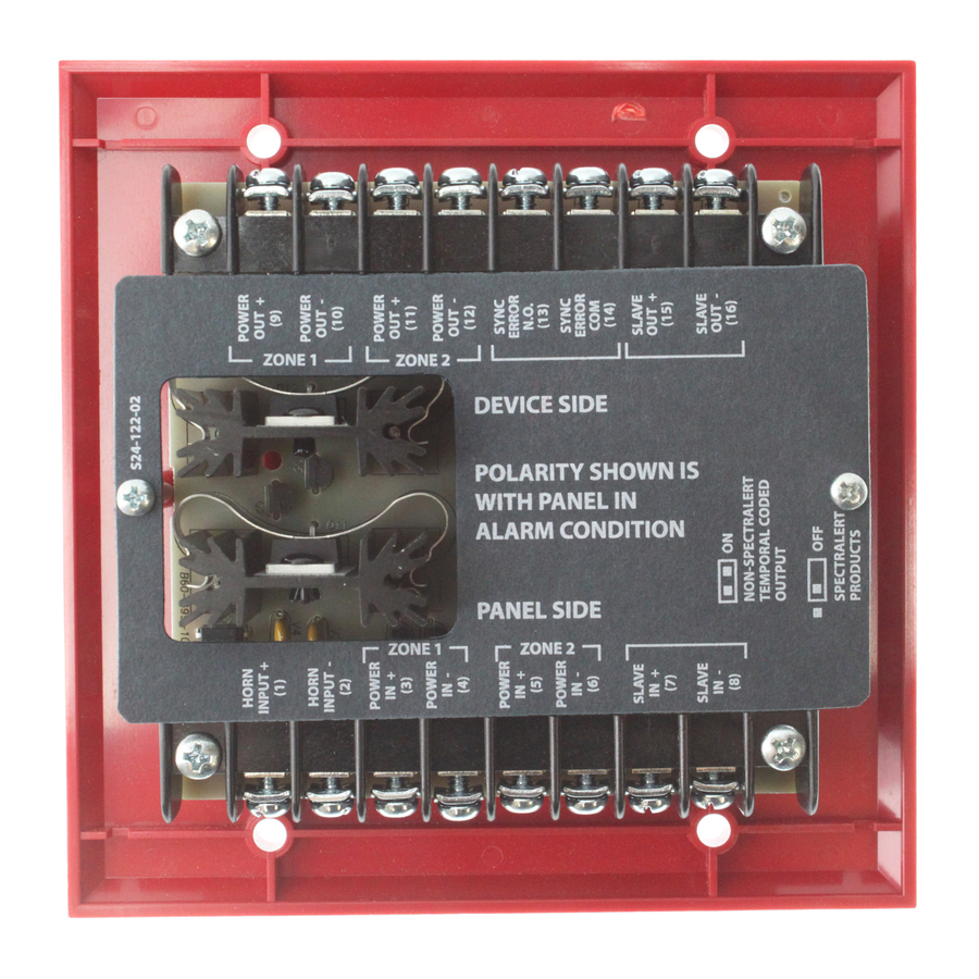
Module Configuration
Each MDL module has the capability of connecting two
Style Y (Class B) circuits or one Style Z (Class A) circuit.
The zone output(s) from the panel are connected to the
zone inputs of the MDL module and the zone output(s)
from the MDL module are connected to the notification
loop(s). Supervision is accomplished in the module by a di-
rect connection between the zone input and the zone out-
put of each of the two zone circuits connected to the
normal end-of-line device. The FACP "sees" the EOL device
through the MDL module. When either or both outputs
from the module are wired to the SpectrAlert products, the
horns and strobes in both zones will be synchronized.
D900-14-00
DC or Full Wave Rectified
11 to 30 Volts
(Note: Supply voltage range at 12 volts – 11 to 17 VDC; at 24 volts – 21 to 30 VDC)
3 A
Average
Voltage
DC
FWR
12 V
10mA 12mA 30mA 31mA 87mA 122mA
24 V
11mA 15mA
0˚ C to 49˚ C (32˚ F to 120˚ F)
UL S4011, S5512
1
3825 Ohio Avenue, St. Charles, Illinois 60174
Peak
In-rush
DC
FWR
DC
FWR
35mA 37mA
198mA 262mA
The MDL module can be configured so that more than two
zones can be synchronized by the interconnection of the
slave input and output (see Figures 1 and 2).
Zone 1 Input:
This input powers the MDL module. This input
must have voltage present from the FACP be-
fore anything will work. This also supplies volt-
age to Zone 1 output.
Zone 2 Input:
This input only supplies voltage to Zone 2 out-
put. Note: If Zone 1 input is not powered, the
notification devices attached to the Zone 2 out-
put will not be powered.
Horn Control:
This input enables the horns on the SpectrAlert
notification appliances. Voltage present means
horns are enabled. No voltage present means
horns are disabled.
Slave In:
Connects to Master MDL Module slave out.
Slave Out:
Connects to Slave MDL slave in.
A Division of Pittway
1-800-SENSOR2, FAX: 630-377-6495
I56-0983-008
Advertisement

Related Manuals for System Sensor MDl Series


Summary of Contents for System Sensor MDl Series
- Page 1 1-800-SENSOR2, FAX: 630-377-6495 H12/24, HC12/24, MA12/24D, PA400, S12XX, S24XX, SC24XX, P12XX, P24XX, PC24XX, SP2C24XX, SP2R24XX, SP2W24XX, DS2475XXX Add suffix “W” for white models. Refer to System Sensor product installation manuals for model specifications. Specifications Voltage Range: DC or Full Wave Rectified 11 to 30 Volts (Note: Supply voltage range at 12 volts –...
- Page 2 Synchronize SpectrAlert Horns and Strobes Figure 1: • Each module can power two 3-amp circuits wired in NOTE: If zone 1 output of module is connected to strobes class B or one 3-amp circuit powered as Class A. or horn/strobes, zone 1 input supply power must •...
- Page 3 NOTE: The MDL Module is factory set with the sync error Figure 5: Wiring for Coded Supplies contacts in the open state. These contacts may close during shipping. Approximately two seconds SPECTRALERT ANY SPECTRALERT HORN STROBE HORN ONLY after power-up, these contacts will open. MULTI CODE SOURCE TO NEXT...
- Page 4 The strobe must have an unin- terrupted source of dc power in order to operate correctly. System Sensor The signal strobe may not be seen. The electronic visual warning signal recommends that the sounder and signal strobe always be used in combi- uses an extremely reliable xenon flash tube.
Need help?
Do you have a question about the MDl Series and is the answer not in the manual?
Questions and answers