System Sensor SC-6 Installation And Maintenance Instructions Manual
Six supervised control module
Hide thumbs
Also See for SC-6:
Advertisement
Quick Links
INSTALLATION AND MAINTENANCE INSTRUCTIONS
SC-6 Six Supervised Control Module
SPECIFICATIONS
Normal Operating Voltage:
Stand-By Current:
Alarm Current:
Temperature Range:
Humidity:
Dimensions:
Accessories:
Wire Gauge:
Maximum NAC Circuit Line Loss:
Power Rating Per Circuit (Speakers):
MaxNAC Current Ratings:
RELAY CONTACT RATINGS:
CURRENT RATING
2 A
3 A
2 A
0.46 A
0.7 A
0.9 A
0.5 A
0.3 A
TABLE 1: SHORT CIRCUIT PROTECTION - UL 864 9TH EDITION REQUIREMENTS
NOTICE TO USERS, INSTALLERS, AUTHORITIES HAVING JURISDICTION, AND OTHER INVOLVED PARTIES
This product incorporates field-programmable software. In order for the product to comply with requirements in the Standard for Control Units and
Accessories for Fire Alarm Systems, UL 864, certain programming features or options must be limited to specific values or not used at all as indicated below.
PROGRAM FEATURE OR OPTION
Disabling short circuit protection
when a single power supply is shared
by multiple NACs
BEFORE INSTALLING
This information is included as a quick reference installation guide. Refer to
the appropriate control panel installation manual for detailed system infor-
mation. If the modules will be installed in an existing operational system,
inform the operator and local authority that the system will be temporarily
out of service. Disconnect the power to the control panel before installing the
modules. This system contains static sensitive components. Always ground
yourself with a proper wrist strap before handling any circuits so that static
charges are removed from the body. The housing cabinet should be metallic
and suitably grounded.
NOTICE: This manual should be left with the owner/user of this equipment.
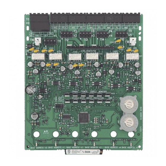
GENERAL DESCRIPTION
The SC-6 Six Supervised Control Module is intended for use in an intelligent
alarm system. Each module is intended for switching applications involving
AC, DC, or audio, which require wiring supervision. A common SLC input is
used for all modules. Each module has its own address. A pair of rotary code
switches is used to set the address of the first module from 01 to 94. The re-
maining modules are automatically assigned to the next five higher addresses.
15-32VDC
2.65 mA @ 24V
35 mA (assumes all six relays have been switched once and all six LEDs solid on)
32°F to 120°F (0°C to 49°C); -10°C to 55°C (For EN54 application only)
10 to 93% Non-condensing
6.8˝H x 5.8˝W x 1.25˝D
CH-6 Chassis; BB-2 Cabinet; BB-6 Cabinet
12-18 AWG
4 VDC
50W @ 70.7VAC 50W @ 25VAC
For class B wiring system, 3A
For class A wiring system, 2A
MAXIMUM VOLTAGE
25 VAC
30 VDC
30 VDC
30 VDC
70.7 VAC
125 VDC
125 VAC
125 VAC
PERMITTED IN
POSSIBLE SETTINGS
UL 864 (Y/N)
No
Enable or Disable short
circuit protection
LOAD DESCRIPTION
PF = 0.35
Resistive
Resistive
(L/R = 20ms)
PF = 0.35
Resistive
PF = 0.75
PF = 0.35
SETTINGS PERMITTED IN UL 864
Enable short circuit protection when a single power supply is
shared by multiple NACs. Short circuit protection can be disabled
only when a power supply is not shared by multiple NACs.
Provisions are included for disabling a maximum of three unused modules
to release the addresses to be used elsewhere. Each module also has panel
controlled green LED indicators. The panel can cause the LEDs to blink, latch
on, or latch off.
In order to synchronize strobes, horn/strobes, and speaker/strobes, a SYNC-1
accessory card (sold separately) must be used with the SC-6. See the SYNC-1
installation manual for details on how to install.
Each module has terminals for connection to an external supply circuit for
powering devices on its NAC.
Each supply must be power limited and its voltage/current limits must be at
or below those specified.
There is a short circuit protection monitor for each module. This is provided to
protect the external power supply against short circuit conditions on the NAC.
1
3825 Ohio Avenue, St. Charles, Illinois 60174
800/736-7672, FAX: 630/377-6495
www.systemsensor.com
APPLICATION
Non-coded
Non-coded
Coded
Non-coded
Non-coded
Non-coded
Non-coded
Non-coded
C0202-01
I56-1802-015
03-11
Advertisement

Related Manuals for System Sensor SC-6


Summary of Contents for System Sensor SC-6
- Page 1 In order to synchronize strobes, horn/strobes, and speaker/strobes, a SYNC-1 out of service. Disconnect the power to the control panel before installing the accessory card (sold separately) must be used with the SC-6. See the SYNC-1 modules. This system contains static sensitive components. Always ground installation manual for details on how to install.
- Page 2 COMPONENTS Following are descriptions of the SC-6 mounting frameworks. There are two mounting options for SC-6 modules: • Up to six SC-6 modules can be installed on a CH-6 in a BB-6 cabinet. BACKBOX MOUNTING • One or two SC-6 modules can be installed in a BB-2 cabinet.
- Page 3 FIGURE 5: INSTALLATION OF REAR MODULE ONLY, METHOD ONE C0226-00 Step 1: Insert the bottom edge of the SC-6 module down into a front slot of the chassis. Step 2: Carefully swing the upper edge of the board towards the back of the chassis until it touches the 11/4˝...
- Page 4 NACs per table 2. The A/B select shunt must be removed prior to connecting the EOL relay coil would normally be connected, should be connected to the the SC-6 to the SLC. The EOL resistors should not be used. The SC-6 is capable amplifier supervision EOL device (figures 12 and 13 are typical).
- Page 5 FIGURE 8: EXAMPLE OF CLASS B, STYLE Y NAC CONFIGURATION WITH A SINGLE SUPPLY DEDICATED TO A SINGLE NAC. EXTERNAL POWER – SUPPLY EOLR-1 BASE ADDRESS – 6 7 8 9 – (–) (–) A2143-10 A/B SELECT DISABLE 1 DISABLE 2 DISABLE 3 POWER-LIMITED TOP OF T0...
- Page 6 FIGURE 10: EXAMPLE OF CLASS A, STYLE Z NAC CONFIGURATION WITH A SINGLE SUPPLY DEDICATED TO A SINGLE NAC. EXTERNAL POWER – SUPPLY EOLR-1 (TYP) (–) (–) BASE ADDRESS – 6 7 8 9 – – A/B SELECT DISABLE 1 DISABLE 2 DISABLE 3 POWER-LIMITED...
- Page 7 FIGURE 12: EXAMPLE OF CLASS B, STYLE Y AUDIO NAC CONFIGURATION. *NOTE 1 – AUDIO AMPLIFIER – (–) (–) BASE ADDRESS – 6 7 8 9 – A2143-10 A/B SELECT DISABLE 1 DISABLE 2 DISABLE 3 POWER-LIMITED TOP OF T0 AND SUPERVISED STATUS SLC +...
-
Page 8: Fcc Statement
12220 Rojas Drive, Suite 700, El Paso TX 79936 USA. Please include a note describing System Sensor warrants its enclosed air duct smoke detector to be free from defects in materials and workmanship under normal use and service for a period of three years the malfunction and suspected cause of failure.
Need help?
Do you have a question about the SC-6 and is the answer not in the manual?
Questions and answers