
Related Manuals for Sunny Health & Fitness SF-RW5624


Summary of Contents for Sunny Health & Fitness SF-RW5624
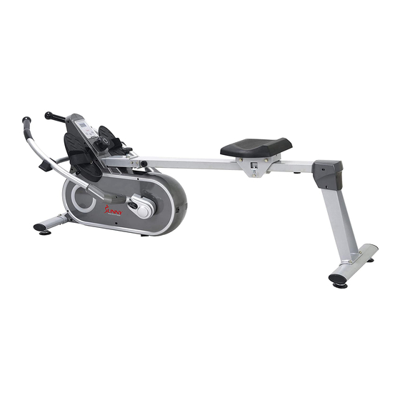
- Page 1 FULL MOTION MAGNETIC ROWING MACHINE SF-RW5624 USER MANUAL IMPORTANT: Read all instructions carefully before using this product. Retain owner’s manual future reference. customer service, please contact: support@sunnyhealthfitness.com...
-
Page 2: Important Safety Information
IMPORTANT SAFETY INFORMATION We thank you for choosing our product. To ensure your safety and health, please use this equipment correctly. It is important to read this entire manual before assembling and using the equipment. Safe and effective use can only be assured if the equipment is assembled, maintained, and used properly. - Page 3 EXPLODED DRAWING...
- Page 4 PARTS LIST Description Description Pedal Adjusting support t4*49.5*20 Bolt M12 *Φ12.5*160*23*S19 Foot leveler Washer d12*Φ24*2 Front stabilizer Screw ST4.2*19*Φ8 Trunk wire Nut M8*H5.5*S14 Sensor wire Foot pad Φ38*10*M8*30 Screw M6*16*Φ12 Washer d6*Φ12*1.2 Below cover for handlebar Limit mat Φ33*Φ8*13 Upper cover for handlebar Limit axle Φ12*80*M6 Handlebar Grommet Φ16...
- Page 5 PARTS LIST Description Description Big chain wheel t2.5*Φ286.8-z140 Adjusting U shape board Chain 1/4”*1/8”*170 Tension control knob Axle for big chain wheel Washer d5 Nut M8*H7.5*S13 Screw M5*12*Φ10.5 Screw M8*12*Φ10*5*S12 Computer SpringΦ2*Φ12*54*N15 Left cover for computer Washer d12*Φ17*0.5 Right cover for computer Idler wheel connect shaft 2 Fixing plate t1.5*56*76 Bearing seat Φ72*11...
- Page 6 HARDWARE PACKAGE...
-
Page 7: Assembly Instructions
ASSEMBLY INSTRUCTIONS STEP 1: Attach the Front Stabilizer (No. 43) to the Main Frame (No. 23) using 2 Screws (No. 36) and 2 Washers (No. 33). Tighten and secure with Allen Wrench (No. B). - Page 8 STEP 2: Attach the Fixing Tube For Left Handlebar (No. 31) and Fixing Tube For Right Handlebar (No. 32) to the Main Frame (No. 23) using 4 Bolts (No. 30), 4 Washers (No. 33) and 4 Nuts (No. 35). Tighten and secure with Spanner (No. A).
-
Page 9: Pedal (
#D S17-19 STEP 3: Fix the 2 Bolts (No. 2) into the bottom hole of Main Frame (No. 23) with Spanner (No. D). Insert the 2 Bolts (No. 2) through the Pedals (No. 1) into the upper hole of the Main Frame (No. -
Page 10: Handlebar 2
10 4PCS STEP 4: Remove 2 Bolts (No. 14) and 2 Nuts (No. 21) from Shaft Sleeves (No. 18) with Spanner (No. D); attach Handlebars (No. 9) into Shaft Sleeves (No. 18) using 2 Bolts (No. 14) and 2 Nuts (No. - Page 11 33* 8*13 1PC 12*1.2 1PC 12 1PC STEP 5: Insert the Saddle (No. 58) into the Sliding Rail (No. 51). Attach the 1 Limit Mat (No. 48) onto the Sliding Rail (No. 51) using 1 Screw (No. 46) and 1 Washer (No.
- Page 12 STEP 6: Attach the Rear Support (No. 56) to the Sliding Rail (No. 51) using 4 Bolts (No. 55), 4 Spring Washers (No. 34) and 4 Washers (No. 33), then tighten with Spanner (No. A). Attach the Left and Right Rear Cover (No. 52 and No. 53) to the Sliding Rail (No. 51) using 4 Screws (No.
- Page 13 STEP 7: Attach the Rear Stabilizer (No. 57) to the Rear Support (No. 56) using 2 Screws (No. 36) and 2 Washers (No. 33). Tighten and secure with Allen Wrench (No. B).
-
Page 14: Main Frame (
STEP 8: Connect Trunk Wire (No. 44) with the Sensor Wire (No. 45). Attach the Sliding Rail (No. 51) to the Main Frame (No. 23) using 1 Bolt (No. 24), 1 Screw (No. 25), then tighten with Allen Wrench (No. B) and Allen Wrench (No. C). Insert Pull Pin (No. - Page 15 ADJUSTMENT GUIDE PEDAL ADJUSTMENT The pedal strap is adjustable and can be personalized to fit the user’s foot size. To adjust the pedal strap, remove the Velcro end of the strap from the mesh side by pulling it upward then to the left. Once removed, you may increase the opening of the pedal strap by pulling the mesh end up and to the right.
-
Page 16: Front Stabilizer
ADJUSTMENT GUIDE MOVE THE MACHINE To move the machine, lift up the rear stabilizer until transportation wheels on the front stabilizer touch the ground. With the wheels on the ground, you can transport the rowing machine to the desired location with ease. ... - Page 17 ADJUSTMENT GUIDE RESISTANCE ADJUSTMENT You can also change the resistance of your workout by changing your hand position on the handlebar. Resistance will feel stronger when your hands are at Position A. Resistance will decrease when your hands are lower on the handlebar, such as at Position C.
-
Page 18: Sliding Rail
ADJUSTMENT GUIDE FOLDING THE MACHINE Figure A When not in use, you can save space by folding the Sliding Rail (No. 51). 1. Disassemble Knob (No. 27) and Washer (No. 3) and pull out the Pull Pin (No. 26). Fold the sliding rail to vertical angle (Figure A). -
Page 19: Computer
MAINTENANCE GUIDE When the battery of computer is used up, please remove the computer from Main Frame (No. 23), and disconnect the Trunk Wire (No. 44) and the link wire of computer; then replace it with new battery. After the replacement, connect Trunk Wire (No. 44) with the link wire of computer and attach the computer into the Main Frame (No. -
Page 20: Specifications
EXERCISE METER Our computerized display console on the Sunny Air Magnetic Rower allows you to tailor a personalized workout by monitoring your progress. During a workout, the display console will alternately and repeatedly display your Time, Count, Calories Burned, Total Count, and Scan (all of the above).
Need help?
Do you have a question about the SF-RW5624 and is the answer not in the manual?
Questions and answers