Sunny Health & Fitness SF-RB4708 User Manual
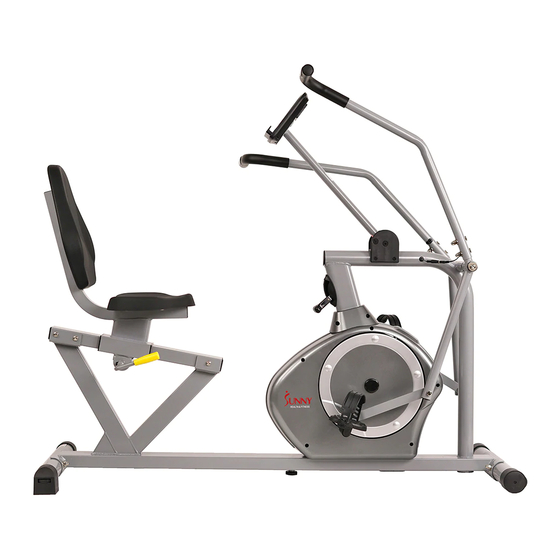
Cross training magnetic recumbent bike
Hide thumbs
Also See for SF-RB4708:
- User manual (17 pages) ,
- User manual (41 pages) ,
- User manual (45 pages)
Advertisement
Quick Links
Download this manual
See also:
User Manual
Advertisement

Related Manuals for Sunny Health & Fitness SF-RB4708


Summary of Contents for Sunny Health & Fitness SF-RB4708
- Page 1 CROSS TRAINING MAGNETIC RECUMBENT BIKE SF-RB4708 USER MANUAL IMPORTANT! Read all instructions carefully before using this product. Retain owner’s manual for future reference. For customer service, please contact: support@sunnyhealthfitness.com...
-
Page 2: Important Safety Notice
IMPORTANT SAFETY NOTICE Note the following precaution before assembling and operating the machine. 1. Assemble the machine exactly as described in the instruction manual. 2. Check all the bolts, nuts and other connections before using the machine for the first time to ensure the machine is in the safe condition. -
Page 3: Exploded Diagram
EXPLODED DIAGRAM... - Page 4 HARDWARE DRAWING & TOOLS Most of the listed assembly hardware have been packaged separately, but some hardware parts have been preassembled. In these instances, simply remove and reinstall the hardware as required.
-
Page 5: Parts List
PARTS LIST DESCRIPTION DESCRIPTION Main frame Back rest Seat tube Cross pan head screw 3L/R Swing tube 1.pr Flat washer D13*2*Ф 26 Slide rail 40L/R Crank 1.pr 5L/R Handlebar 1.pr Cap S14 Front stabilizer Cap S13 Rear stabilizer Sensor wire Adjustment Handle Hex bolt M8*50 Square neck bolt... -
Page 6: Assembly Instruction
ASSEMBLY INSTRUCTION STEP 1 1. Attach the Front Stabilizer (6) and the Rear Stabilizer (7) to the Main Frame (1) with the Square Neck Bolts (9), Arc Washers (12) and Ball Cap Nuts (11). 2. Attach the Adjustable Pad (28) to the Main Frame (1). STEP 2 1. - Page 7 STEP 3 1. Attach the Seat Rest (37) to the Seat Tube (2) with Hex Pan Head Screws (14) and Washers (15). 2. Attach the Seat (36) to the Seat Tube (2) with Hex Pan Head Screws (14) and Washers (15). STEP 4 1.
- Page 8 STEP 5 1. Attach the Handlebar (5L/R) to the Swing Tube (3L/R) with Square Bolts (58), Arc Washers (59) and Ball Cap Nuts (11). Connect the Pulse Wire (60) with Extension Wire (49). 2. Lift up the Computer Tube (13), and lock the Hex Screw (64) to the Fixed bracket (63) by the bottom holes of the Computer Tube (13).
- Page 9 Adjusting the Saddle Position To move the saddle forward or backward, while seated on the bike, pull the Adjustment Handle (8) towards you. Move the saddle. Push the Adjustment Handle (8) forward to secure. Adjusting the Level If the bike is not level, adjust the End Caps (26).
- Page 10 Moving the Bike Lift the bike by the Rear Stabilizer (7) until the wheels on the Front Stabilizer (6) touch the floor. Now you can move the bike.
- Page 11 EXERCISE COMPUTER INSTRUCTIONS BUTTONS 1. MODE Press this button to change display or choose the window needs to be set. In monitor status, hold this button for 3 seconds to reset all value to zero. 2. SET iii. To set value of Time, Distance, Calorie and Pulse when not in scan mode 3.
- Page 12 SPECIFICATIONS Auto Scan Every 6seconds Running Time 00:00~ 99:00(Minute: Second) The max pick-up signal is Current Speed 999.9 MILE/H FUNCTION Trip Distance 0.0 ~ 999.9 MILE Calories 0 ~ 999.9 Kcal Total Distance 0 ~ 9999 MILE Pulse Rate 40-240BPM Battery Type 2 pcs of SIZE-AAAand UM-4 0℃...
Need help?
Do you have a question about the SF-RB4708 and is the answer not in the manual?
Questions and answers
Need Parts List
The parts list for the Sunny Health & Fitness SF-RB4708 includes:
1. Main Frame – 1
2. Seat Tube – 1
3L/R. Swing Tube – 1 pair
4. Slide Rail – 1
5L/R. Handlebar – 1 pair
6. Front Stabilizer – 1
7. Rear Stabilizer – 1
8. Adjustment Handle – 1
9. Square Neck Bolt M8xL73 – 4
10. Cross Pan Head Screw ST4.2x18 – 4
11. Ball Cap Nut M8 – 8
30. Spacer Φ36*Φ21*11.8 – 2
37. Back Rest – 1
38. Cross Pan Head Screw – 4
39. Flat Washer D13x2xΦ26 – 2
40L/R. Crank – 1 pair
41. Cap S14 – 2
42. Cap S13 – 2
43. Sensor Wire – 1
44. Hex Bolt M8x50 – 2
45. Square Plug 60x30x1.5 – 1
46. Connecting Board – 2
47. Alloy Bushing – 1
58. Hex Bolt M8x40 – 4
59. Plastic Flat Washer Φ20xD8.5xR12.5 – 4
64. Hex Bolt M8x70 – 1
71. Washer Φ12x47 – 1
88. Hex Bolt M8xL60x120 – 1
89. Nylon Nut M8 – 1
90. Flange Nut M10x1 – 2
91. Conical Thin Nut M10x1xH5 – 2
94. Flywheel – 1
95. Flywheel Axle – 1
96. Middle Axle – 1
97. Flange Nut M10x1.25 – 2
98. Spring Stop Collar – 2
99. Bearing 6003RZ – 2
101. Nylon Nut M6 – 4
102. Spring Washer D6 – 4
103. Spanner S13-14-15 – 1
104. Spanner S13-14 – 1
105. Allen Wrench S5 – 1
106. Allen Wrench S6 –
This answer is automatically generated