Hypertherm powermax45 Operator's Manual
Plasma arc cutting system
Hide thumbs
Also See for powermax45:
- Operator's manual (174 pages) ,
- Service manual (149 pages) ,
- Field service bulletin (30 pages)
Table of Contents
Advertisement
Quick Links
Advertisement
Table of Contents

Related Manuals for Hypertherm powermax45


Summary of Contents for Hypertherm powermax45
- Page 1 Plasma arc cutting system Operator Manual – 805780 Revision 1...
- Page 2 Register your new Hypertherm system Register your product on-line at www.hypertherm.com/registration for easier technical and warranty support. You can also receive updates on new Hypertherm products and a free gift as a token of our appreciation. For your records Serial number:...
- Page 3 Revision 1 – October 2010 Hypertherm, Inc. Hanover, NH USA www.hypertherm.com email: info@hypertherm.com © Copyright 2010 Hypertherm, Inc. All Rights Reserved Hypertherm and Powermax are trademarks of Hypertherm, Inc. and may be registered in the United States and/or other countries.
-
Page 4: Electromagnetic Compatibility
COMPAtIbIlItY (eMC) Introduction electromagnet i c problems in the sur r ound i ng area. The following shall be taken into a ccount: Hypertherm’s CE-marked equipment is built a. O ther supply cables, control cables, in compliance with standard EN60974-10. signalling and telephone ca b les; above, The equipment should be in s talled and used below and adjacent to the cutting equipment. in accordance with the information be l ow to achieve elec t ro m ag n et i c com p at i b il i t y. - Page 5 eleCtROMAGNetIC COMPAtIbIlItY (eMC) earthing of workpiece be necessary to take addi t ional precautions such as fil t er i ng of the mains supply. Where the workpiece is not bonded to earth Consideration should be given to shield i ng the for electrical safety, nor connected to earth supply cable of per m a n ent l y installed cutting because of its size and position, for ex- equip m ent, in metallic conduit or equiv a l ent. ample, ship’s hull or building steel w ork, a Shielding should be elec t ri c al l y continuous con ...
-
Page 6: Warranty
WARRANtY Attention This warranty shall not apply to any Powermax brand power supplies that have been used with Genuine Hypertherm parts are the factory- phase converters. In addition, Hypertherm does recommended r eplacement parts for your not warranty systems that have been damaged Hypertherm system. Any damage or injury as a result of poor power quality, whether from caused by the use of other than genuine phase converters or incoming line power. This Hypertherm parts may not be covered by the warranty shall not apply to any Product which Hypertherm warranty, and will constitute misuse has been incorrectly installed, modified, or of the Hypertherm Product. otherwise damaged. You are solely responsible for the safe use of Hypertherm provides repair, replacement or the Product. Hypertherm does not and cannot adjustment of the Product as the sole and make any guarantee or warranty regarding the exclusive remedy, if and only if the warranty safe use of the product in your e nvironment. set forth herein properly is invoked and applies. Hypertherm, at its sole option, shall General repair, replace, or adjust, free of charge, any defective Products covered by this warranty Hypertherm, Inc. warrants that its Products which shall be returned with Hypertherm’s prior shall be free from defects in materials and authorization (which shall not be unreasonably workmanship for the specific periods of time withheld), properly packed, to Hypertherm’s ... - Page 7 WARRANtY WARRANtY limitation of liability Distributors/OEMs may offer different or additional warranties, but Distributors/OEMs In no event shall Hypertherm be liable to are not authorized to give any additional any person or entity for any incidental, warranty protection to you or make any consequential direct, indirect, punitive representation to you purporting to be binding or exemplary damages (including but upon Hypertherm. not limited to lost profits) regardless of whether such liability is based on breach Distributors/OEMs may offer different or ...
- Page 8 WARRANtY transfer of rights You may transfer any remaining rights you may have hereunder only in connection with the sale of all or substantially all of your assets or capital stock to a successor in interest who agrees to be bound by all of the terms and conditions of this Warranty. Within thirty (30) days before any such transfer occurs, you agree to notify in writing Hypertherm, which reserves the right of approval. Should you fail timely to notify Hypertherm and seek its approval as set forth herein, the Warranty set forth herein shall be null and void and you will have no further recourse against Hypertherm under the Warranty or otherwise. Compliance Information 9/10...
-
Page 9: Safety Information
Safety information Before operating any Hypertherm equipment, read the separate Safety and Compliance Manual (80669C) included with your product for important safety information. -
Page 10: Table Of Contents
T45v torch dimensions ............................ 1-5 T45m torch dimensions ............................ 1-5 T45v and T45m torch specifications ......................1-6 Symbols and markings ............................1-7 IEC symbols .............................. 1-8 Section 2 POWeR SUPPlY SetUP Unpack the Powermax45 ..........................2-2 Claims ................................ 2-2 Contents ..............................2-2 Position the power supply..........................2-3 Prepare the electrical power ........................... 2-3 Voltage configurations ..........................2-3 Install a line-disconnect switch ...................... - Page 11 Connect the remote-start pendant ....................3-26 Connect a machine interface cable ....................3-27 Connect the torch lead ...........................3-30 Section 4 OPeRAtION Controls and indicators ............................ 4-2 Front controls and LEDs ........................4-2 Rear controls ............................4-3 Operate the Powermax45 ..........................4-4 Connect the electrical power and gas supply .................. 4-4 Turn ON the system ..........................4-4 Set the mode switch ..........................4-5 Adjust the gas pressure ......................... 4-5 Check the indicator LEDs ........................4-6 Attach the work clamp ........................... 4-7 Understand duty-cycle limitations ...
- Page 12 OF CONteNtS Remove and replace the cover and Mylar® barrier ................. 5-8 Replace the work lead (CSA and CE) .....................5-10 Replace the gas filter element ......................5-11 Section 6 PARtS Power supply parts ............................6-2 T45v hand torch parts............................6-5 T45v hand torch consumables ......................6-6 T30v (Powermax30) 30 A consumables ................... 6-6 T45m machine torch parts ..........................6-7 T45m machine torch consumables ..................... 6-8 Accessory parts..............................6-8 Powermax45 labels ............................6-8 powermax Operator Manual ...
- Page 13 tAble OF CONteNtS powermax Operator Manual...
-
Page 14: Where To Find Information 1
Section 1 SPeCIFICAtIONS In this section: System description ............................1-2 Where to find information ..........................1-2 Power supply dimensions and weights ......................1-3 Dimensions ............................... 1-3 Weights ..............................1-3 Power supply ratings ............................1-4 T45v torch dimensions ............................ 1-5 T45m torch dimensions ............................ 1-5 T45v and T45m torch specifications ......................1-6 Symbols and markings ............................1-7 IEC symbols .............................. 1-8 powermax ... -
Page 15: System Description
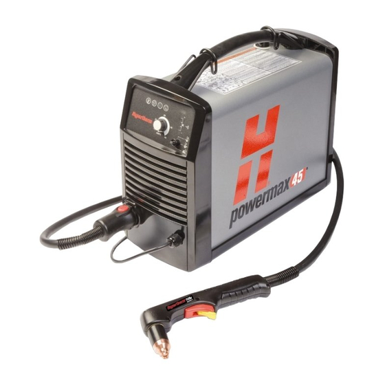
SPeCIFICAtIONS System description The Powermax45 is a highly portable, 45-amp, handheld and mechanized plasma cutting system appropriate for a wide range of applications. The Powermax45 uses air or nitrogen to cut electrically conductive metals, such as mild or stainless steel or aluminum. With it, you can cut thicknesses up to 1 inch (25.4 mm) and pierce thicknesses up to 3/8 inch (9.5 mm). The standard Powermax45 system includes a complete set of the consumables needed for cutting (shield, retaining cap, swirl ring, nozzle, electrode), 2 spare electrodes, 2 spare nozzles, gouging consumables (handheld configurations only), a quick-disconnect air fitting (1/4 NPT on CSA units and 1/4 NPT x G-1/4 BSPP on CE units), a consumables box, a shoulder strap, an Operator Manual, a Quick Setup Card, and a Setup DVD. Mechanized configurations include a remote-start pendant as well. You can order additional consumables and accessories – such as the plasma cutting guide – from any Hypertherm distributor. See Section 6, Parts, for a list of spare and optional parts. The power cords on the CSA power supplies are shipped with a 50 A, 250 V plug (NEMA 6-50P) on the power cord. The CE units are shipped without a plug on the power cord. See Prepare the electrical power in Section 2 for more information. Where to find information System specifications such as size, weight, detailed electrical specifications, and cut speeds can be found in this section. For information on: • S afety information — see the Safety and Compliance Manual for detailed safety information. • S etup requirements, including power requirements, grounding, power cord configurations, extension cord requirements, and generator recommendations — see Section 2, Power supply setup. • H andheld and machine torch consumables, cut charts, and torch setup information — see ... -
Page 16: Power Supply Dimensions And Weights
SPeCIFICAtIONS Power supply dimensions and weights Dimensions 13.7 in (34.8 cm) 12.19 in (31 cm) 16.75 in 6.75 in (42.6 cm) (17.2 cm) Weights Power supply weights given below include the hand torch with 20 ft (6.1 m) lead, a 20 ft (6.1 m) work lead, and a 10 ft (3 m) power cord. • C SA power supply: 37 lbs (16.8 kg) • C E 230 V power supply: 36.5 lbs (16.6 kg) • CE 400 V power supply: 35 lbs (15.9 kg) powermax Operator Manual... -
Page 17: Power Supply Ratings
SPeCIFICAtIONS Power supply ratings Rated open-circuit voltage (U CSA/CE, single-phase 275 VDC CE, 3-phase Rated output current (I 20 A to 45 A Rated output voltage (U 132 VDC Duty cycle at 40° C 50 % (I =45 A, U =132 V) (See data plate on power supply for 60 % (I =41 A, U =132 V) more information on duty cycle.) 100 % (I =32 A, U =132 V) Operating temperature 14° to 104° F (-10° to 40° C) Storage temperature -13° to 131° F (-25° to 55° C) Power factor 200–240 V CSA, 230 V CE, 1-phase 0.99 400 V, 3-phase CE 0.94 Input voltage (U )/ Input current (I ) at 200–240 VAC / 34–28 A (CSA) rated output (U , I 2 MAX 2 MAX... -
Page 18: T45V Torch Dimensions
SPeCIFICAtIONS t45v torch dimensions 8.72 in ( 22.1 cm) 8.5 in (21.6 cm) 3.28 in (8.3 cm) 75° angle 1.58 in 1.91 in (4.9 cm) (4.0 cm) 1 in (2.5 cm) t45m torch dimensions 14.36 in (36.5 cm) 1 in 1.43 in (3.6 cm) outer 12 in (2.5 cm) dimension, 1.3 in (30.5 cm) (3.3 cm) flat sides 13 in (33.0 cm) powermax Operator Manual... -
Page 19: T45V And T45M Torch Specifications
SPeCIFICAtIONS t45v and t45m torch specifications Handheld cut capacity (material thickness) Recommended cut capacity (hand 1/2 in (12.7 mm) cutting) Maximum cut capacity (hand cutting 3/4 in (19.1 mm) or mechanized edge start) Severance capacity (hand cutting or 1 in ( 25.4 mm) mechanized edge start) Mechanized pierce capacity (material thickness) Pierce capacity (for edge starts, the capacities are 3/8 in (9.5 mm) the same as the handheld capacities) Recommended cut speed (on mild steel) 1/4 in (6.35 mm) 60 ipm (1524 mm/min) 3/8 in (9.53 mm) 32 ipm (813 mm/min) 1/2 in (12 mm) 20 ipm (508 mm/min) 3/4 in (18 mm) 8 ipm (203 mm/min) -
Page 20: Symbols And Markings
CSA mark Hypertherm products with a CSA mark meet the United States and Canadian regulations for product safety. The products were evaluated, tested, and certified by CSA-International. Alternatively the product may have a mark by one of the other Nationally Recognized Testing Laboratories (NRTL) accredited in both the United States and Canada, such as Underwriters Laboratories, Incorporated (UL) or TÜV. Ce marking T he CE marking signifies the manufacturer’s declaration of conformity to applicable European directives and standards. Only those versions of Hypertherm products with a CE marking located on or near the data plate have been tested for compliance with the European Low Voltage Directive and the European Electromagnetic Compatibility (EMC) Directive. EMC filters needed to comply with the European EMC Directive are incorporated within versions of the product with a CE marking. GOSt-R mark CE versions of Hypertherm products that include a GOST-R mark of conformity meet the product safety and EMC requirements for export to the Russian Federation. c-tick mark C E versions of Hypertherm products with a c-Tick mark comply with the EMC regulations required for sale in Australia and New Zealand. CCC mark The China Compulsory Certification (CCC) mark indicates that the product has been tested and found compliant with product safety regulations required for sale in China. powermax Operator Manual... -
Page 21: Iec Symbols
SPeCIFICAtIONS IeC symbols The following symbols may appear on the power supply data plate, control labels, switches, and LEDs: Power is ON Direct current (DC) Alternating current Power is OFF (AC) An inverter-based power source, either 1-phase or Plasma torch cutting 3-phase Plate metal cutting Volt/amp curve, “drooping” characteristic Expanded metal cutting Power is ON (LED) Gouging System fault (LED) AC input power Inlet gas pressure (LED) connection The terminal for the Missing or loose external protective consumables (LED) (earth) conductor Power supply is out of Gas test mode temperature range (LED) powermax Operator Manual... -
Page 22: Unpack The Powermax45 2
Section 2 POWeR SUPPlY SetUP In this section: Unpack the Powermax45 ..........................2-2 Claims ................................ 2-2 Contents ..............................2-2 Position the power supply..........................2-3 Prepare the electrical power ........................... 2-3 Voltage configurations ..........................2-3 Install a line-disconnect switch ......................2-4 Requirements for grounding ......................... 2-4 Power cord considerations ..........................2-5 Extension cord recommendations ....................... 2-5 Generator recommendations ........................ 2-7 Prepare the gas supply ... -
Page 23: Unpack The Powermax45
POWeR SUPPlY SetUP Unpack the Powermax45 1. V erify that all items on your order have been received in good condition. Contact your distributor if any parts are damaged or missing. 2. I nspect the power supply for damage that may have occurred during shipping. If there is evidence of damage, refer to Claims, below. All communications regarding this equipment must include the model number and the serial number located on the bottom of the power supply. 3. B efore you set up and operate this Hypertherm system, read the Safety and Compliance Manual. Claims • C laims for damage during shipment – If your unit was damaged during shipment, you must file a claim with the carrier. Hypertherm will furnish you with a copy of the bill of lading upon request. If you need additional assistance, call the nearest Hypertherm office listed in the front of this manual. • C laims for defective or missing merchandise – If any component is missing or ... -
Page 24: Position The Power Supply
POWeR SUPPlY SetUP Position the power supply Locate the Powermax45 near an appropriate 200–240 volt power receptacle for CSA or CE 1-phase power supplies, or a 400 volt receptacle for 3-phase CE power supplies. The Powermax45 has a 10-foot (3 m) power cord. Allow at least 10 inches (0.25 m) of space around the power supply for proper ventilation. Prepare the electrical power The maximum output voltage will vary based on your input voltage and the circuit’s amperage. Because the current draw varies during startup, slow-blow fuses are recommended as shown in the chart below. Slow-blow fuses can withstand currents up to 10 times the rated value for short periods of time. Voltage configurations The following chart shows the maximum rated output for typical combinations of input voltage and amperage. Acceptable input voltages can be ±10% of the values given below. Caution: Protect the circuit with appropriately sized time-delay (slow-blow) fuses and a line-disconnect switch. Input Input Recommended... -
Page 25: Install A Line-Disconnect Switch
• H ave one OFF and one ON position that are clearly marked with O (OFF) and I (ON). • H ave an external operating handle that can be locked in the OFF position. • C ontain a power-operated mechanism that serves as an emergency stop. • H ave slow-blow fuses installed as recommended in the table on the previous page. Requirements for grounding To ensure personal safety, proper operation, and to reduce electromagnetic interference (EMI), the Powermax45 must be properly grounded: • T he power supply must be grounded through the power cord according to national and local electrical codes. • S ingle-phase service must be of the 3-wire type with a green or green/yellow wire for the protective earth ground and must comply with national and local requirements. Do not use a 2-wire service. • T hree-phase service (CE only) must be of the 4-wire type with a green or green/yellow wire ... -
Page 26: Power Cord Considerations
POWeR SUPPlY SetUP Power cord considerations Powermax45 power supplies are shipped with CSA and CE power cord configurations. The power cords on the CSA power supplies are shipped with a 50 A, 250 V plug (NEMA 6-50P) on the power cord. The CE power supplies are shipped without a plug on the power cord. Obtain the correct plug for your unit (either 230 V or 400 V) and location have it installed by a licensed electrician. extension cord recommendations Any extension cord must have an appropriate wire size for the cord length and system voltage. Use a cord that meets national and local codes. The tables on the next page provides the recommended gauge size for various lengths and input voltages. The lengths in the tables are the length of the extension cord only; they do not include the power supply’s power cord. powermax Operator Manual ... - Page 27 POWeR SUPPlY SetUP extension cord recommendations english Input voltage Phase < 10 ft 10–25 ft 25–50 ft 50–100 ft 100–150 ft 208 VAC 8 AWG 8 AWG 8 AWG 6 AWG 4 AWG 220 VAC 8 AWG 8 AWG 8 AWG 6 AWG 4 AWG 200–240 VAC 8 AWG 8 AWG 8 AWG 6 AWG 4 AWG 380 VAC 12 AWG 12 AWG 12 AWG...
-
Page 28: Generator Recommendations
POWeR SUPPlY SetUP Generator recommendations When using a generator with the Powermax45, it should produce 240 VAC nominal current. engine engine drive Performance drive rating output current 8 KW 33 A Good arc stretch at 45 A cutting current Limited arc stretch at 45 A cutting current 6 KW 25 A Good arc stretch at 30 A cutting current Notes: B ased on the generator rating, age, and condition, adjust the cutting current as needed. I f a fault occurs while using a generator, turning the power switch quickly to OFF and then to ON again (sometimes called a “quick reset”) may not clear the fault. Instead, turn OFF the power supply and wait 30 to 45 seconds before turning to ON again. Prepare the gas supply The gas supply for the Powermax45 can be shop-compressed or cylinder-compressed. A high- pressure regulator must be used on either type of supply and must be capable of delivering gas to the filter on the power supply at 360 scfh @ 90 psi (170 l/min @ 6.2 bar). WARNING Do not allow the gas supply pressure to exceed 135 psi (9.3 bar). -
Page 29: Connect The Gas Supply
POWeR SUPPlY SetUP Connect the gas supply Connect the gas supply to the power supply using an inert-gas hose with a 3/8 inch (9.5 mm) internal diameter and a 1/4 NPT quick-disconnect coupler, or a 1/4 NPT x G-1/4 BSPP (CE units) quick-disconnect coupler. 80 – 100 psi (5.5 – 6.9 bar) gas supply (maximum 135 psi or 9.3 bar) with a flow rate of at least 350 scfh (165.2 l/min). The recommended flow rate and pressure is 360 scfh @ 90 psi (170 l/min @ 6.2 bar). Additional gas filtration When site conditions introduce moisture, oil, or other contaminants into the gas line, use a 3-stage coalescing filtration system, such as the Eliminizer filter kit (part number 128647) available from Hypertherm distributors. A 3-stage filtering system works as shown below to clean contaminants from the gas supply. Oil filter Oil vapor filter Water and particle filter Gas supply Powermax45 The filtering system should be installed between the quick-disconnect coupler and the power supply. powermax Operator Manual... -
Page 30: Introduction 3
Section 3 torch setup In this section: Introduction ................................. 3-2 Consumable life ..............................3-2 Hand torch setup ............................... 3-3 Choose the consumables ........................3-3 Install the consumables .......................... 3-5 Machine torch setup............................3-6 Mount the torch ............................3-6 Choose the consumables (cut charts) ....................3-8 Align the torch ............................3-26 Connect the remote-start pendant ....................3-26 Connect a machine interface cable ....................3-27 Connect the torch lead ...........................3-30 powermax ... -
Page 31: Introduction
SetUP Introduction Both T45v handheld torch and the T45m machine torch, are available for the Powermax45. The torch quick disconnect makes it easy to remove the torch for transport or to switch from one torch to the other if your applications require the use of both torches. This section explains how to set up your torch and choose the appropriate consumables for the job. Consumable life How often you will need to change the consumables on your Powermax45 will depend on a number of factors: • T he thickness of the metal being cut. • T he length of the average cut. • W hether you are doing machine or hand cutting. • T he air quality (presence of oil, moisture, or other contaminants). • W hether you are piercing the metal or starting cuts from the edge. • P roper torch-to-work distance when gouging or cutting with unshielded consumables. • P roper pierce height. -
Page 32: Hand Torch Setup
SetUP Hand torch setup Consumables Safety trigger Choose the consumables The Powermax45 with the T45v handheld torch comes with a full set of consumables for cutting installed on the torch, spare electrodes and nozzles in the consumables box, and consumables for gouging in the consumables box. In non-CE-regulated countries, you can also purchase unshielded consumables that are useful for certain applications. With shielded consumables, you drag the torch tip along the metal to cut. With unshielded consumables, you must keep the torch a small distance, about .08 inch (2 mm), away from the metal. Unshielded consumables generally have a shorter life than shielded consumables; however, you may find that visibility and accessibility are better for some applications. Consumables for hand cutting are shown on the next page. Notice that the retaining cap, swirl ring, and electrode are the same for shielded, unshielded, and gouging applications. Only the shield (deflector for unshielded consumables) and the nozzle are different. For the best cut quality on thin stainless steel, you may prefer to reduce the amperage setting to 30 amps and use the T30v (Powermax30) 30 A consumables available from Hypertherm. powermax Operator Manual ... - Page 33 tORCH SetUP t45v shielded consumables 220674 220713 220671 220670 220669 Shield Retaining cap Nozzle Swirl ring Electrode t45v gouging consumables 220675 220713 220672 220670 220669 Shield Retaining cap Nozzle Swirl ring Electrode t45v unshielded consumables* 220717 220713 220670 220669 220718 Deflector Retaining cap Swirl ring Electrode Nozzle * ...
-
Page 34: Install The Consumables
tORCH SetUP Install the consumables WARNING INStANt-ON tORCHeS PlASMA ARC CAN CAUSe INJURY AND bURNS the plasma arc comes on im me di ate ly when the torch is activated. Make sure the power is OFF before changing the consumables. To operate the T45v torch, it must have a complete set of consumable parts installed: a shield or ... -
Page 35: Machine Torch Setup
tORCH SetUP Machine torch setup Consumables Positioning sleeve Gear rack Brass strain Strain relief relief Before using the T45m, you must: • M ount the torch on your cutting table or other equipment. • Choose and install the consumables. • A lign the torch. • A ttach the torch lead to the power supply. • S et up the power supply for remote starting with either the remote-start pendant or a machine interface cable. Mount the torch Depending on the type of cutting table you have, you may or may not need to disassemble the torch to route it through the track and mount it. If your cutting table’s track is large enough for you to thread the torch through it without removing the torch body from the lead, do so and then attach the torch to the lifter per the manufacturer’s instructions. Note: T he T45m can be mounted on a wide variety of X-Y tables, track burners, pipe bevelers, and other equipment. Install the torch per the manufacturer’s instructions and ... - Page 36 tORCH SetUP 3. D isconnect the wires for the cap-sensor switch at the connector in the middle. Gas supply line connection Wire connector for Screw to connect the the cap-sensor switch power cable to the plunger 4. U se a #2 Phillips screwdriver and a 1/4-inch nut driver (or adjustable wrench) to remove the screw and nut that secure the torch’s power cable to the plunger. (Turn the plunger if necessary to gain access to the screw.) 5. U se 5/16-inch (8 mm) and 3/8-inch (or adjustable) wrenches to loosen the nut that secures the gas supply line to the torch lead. Set the torch body aside. Note: C over the end of the gas line on the torch lead with tape to keep dirt and other contaminants from getting in the gas line when you route the lead through the track. 6. R oute the torch lead through the cutting table’s track. 7. R eattach the torch’s power cable to the torch plunger using the screw and nut. Rotate the plunger so that the screw does not interfere with the cap-sensor switch.
-
Page 37: Choose The Consumables (Cut Charts)
tORCH SetUP Choose the consumables (cut charts) WARNING INStANt-ON tORCHeS PlASMA ARC CAN CAUSe INJURY AND bURNS the plasma arc comes on im me di ate ly when the torch is activated. Make sure the power is OFF before changing the consumables. A complete set of shielded consumables is shipped with the T45m machine torch. In addition, an ... - Page 38 tORCH SetUP t45m shielded consumables Air flowrate (lpm) Mild steel Metric Cold 165.2 Recommended Maximum torch- Material Pierce to-work Initial pierce Voltage Voltage current thickness time delay Speed Speed distance height (amps) (mm) (sec) (mm/min) (mm/min) (mm) 9150 10160* 8650 10160* 30 ...
- Page 39 tORCH SetUP t45m shielded consumables Air flowrate (scfh) Mild Steel english Cold Recommended Maximum torch- Pierce time Material Initial pierce Voltage Voltage current to-work delay Speed Speed thickness height (amps) distance (sec) (ipm) (ipm) 0.018 in 400* (26 Ga) 0.030 in 400* (22 Ga) 30 ...
- Page 40 tORCH SetUP t45m shielded consumables Air flowrate (lpm) Stainless steel Metric Cold 165.2 Recommended Maximum torch- Material Pierce to-work Initial pierce Voltage Voltage current thickness time delay Speed Speed distance height (amps) (mm) (sec) (mm/min) (mm/min) (mm) 9150 10160* 8650 10160* 30 ...
- Page 41 tORCH SetUP t45m shielded consumables Air flowrate (scfh) Stainless steel english Cold Recommended Maximum torch- Pierce time Material to-work Initial pierce Voltage Voltage current delay Speed Speed thickness distance height (amps) (sec) (ipm) (ipm) (in) 0.018 in 400* (26 Ga) 0.030 in 400* (22 Ga) 30 ...
- Page 42 tORCH SetUP t45m shielded consumables Air flowrate (lpm) Aluminum Metric Cold 165.2 Recommended Maximum torch- Material Pierce to-work Initial pierce Voltage Voltage current thickness time delay Speed Speed distance height (amps) (mm) (sec) (mm/min) (mm/min) (mm) 9150 10160* 3.8 mm 250% 8650 10160* 5450...
- Page 43 tORCH SetUP t45m shielded consumables Air flowrate (scfh) Aluminum english Cold Recommended Maximum torch- Pierce time Material to-work Initial pierce Voltage Voltage current delay Speed Speed thickness distance height (amps) (sec) (ipm) (ipm) (in) 0.018 in 400* (26 Ga) 0.060 in 30 0.06 0.15 in 250% 400* (16 Ga)
- Page 44 tORCH SetUP t45m unshielded consumables 220717 220713 220670 220669 220718 Deflector Retaining cap Swirl ring Electrode Nozzle Air flowrate (lpm) Mild steel Metric Cold 165.2 Recommended Maximum torch- Material Pierce to-work Initial pierce Voltage Voltage current thickness time delay Speed Speed distance height (amps) (mm)
- Page 45 tORCH SetUP t45m unshielded consumables Air flowrate (scfh) Mild Steel english Cold Recommended Maximum torch- Pierce time Material to-work Initial pierce Voltage Voltage current delay Speed Speed thickness distance height (amps) (sec) (ipm) (ipm) (in) 0.018 in 400* (26 Ga) 0.030 in 400* (22 Ga) 30 ...
- Page 46 tORCH SetUP t45m unshielded consumables Air flowrate (lpm) Stainless steel Metric Cold 165.2 Recommended Maximum torch- Material Pierce to-work Initial pierce Voltage Voltage current thickness time delay Speed Speed distance height (amps) (mm) (sec) (mm/min) (mm/min) (mm) 9144 10160* 8128 10160* 30 ...
- Page 47 tORCH SetUP t45m unshielded consumables Air flowrate (scfh) Stainless steel english Cold Recommended Maximum torch- Pierce Material to-work Initial pierce Voltage Voltage current time delay Speed Speed thickness distance height (amps) (sec) (ipm) (ipm) (in) 0.018 in 400* (26 Ga) 0.030 in 400* (22 Ga) 30 ...
- Page 48 tORCH SetUP t45m unshielded consumables Air flowrate (lpm) Aluminum Metric Cold 165.2 Recommended Maximum torch- Material Pierce to-work Initial pierce Voltage Voltage current thickness time delay Speed Speed distance height (amps) (mm) (sec) (mm/min) (mm/min) (mm) 8900 10160* 5.0 mm 250% 8100 10160* 5700...
- Page 49 tORCH SetUP t45m unshielded consumables Air flowrate (scfh) Aluminum english Cold Recommended Maximum torch- Pierce time Material to-work Initial pierce Voltage Voltage current delay Speed Speed thickness distance height (amps) (sec) (ipm) (ipm) (in) 0.018 in 400* (26 Ga) 0.060 in 30 0.08 0.20 in 250% 400* (16 Ga)
- Page 50 tORCH SetUP t30v (Powermax30) 30 A consumables 220483 220479 220478 220569 220480 Retaining cap Swirl ring Electrode Optional Nozzle deflector Mild steel Air flowrate (lpm) Metric 131.2 Cold 146.3 Recommended Maximum torch- Material Pierce to-work Initial pierce Voltage Voltage current thickness time delay Speed Speed distance...
- Page 51 tORCH SetUP t30v (Powermax30) 30 A consumables Air flowrate (scfh) Mild steel english Cold Recommended Maximum torch- Material Pierce to-work Initial pierce Voltage Voltage current thickness time delay Speed Speed distance height (amps) (in) (sec) (ipm) (ipm) (in) 0.018 400* (26 Ga) 0.030 ...
- Page 52 tORCH SetUP t30v (Powermax30) 30 A consumables Air flowrate (lpm) Stainless steel 131.2 Metric Cold 146.3 Recommended Maximum torch- Material Pierce to-work Initial pierce Voltage Voltage current thickness time delay Speed Speed distance height (amps) (mm) (sec) (mm/min) (mm/min) (mm) 8900 10160* 8100...
- Page 53 tORCH SetUP t30v (Powermax30) 30 A consumables Air flowrate (scfh) Stainless steel english Cold Recommended Maximum torch- Material Pierce to-work Initial pierce Voltage Voltage current thickness time delay Speed Speed distance height (amps) (in) (sec) (ipm) (ipm) (in) 0.018 400* (26 Ga) 0.030 ...
- Page 54 tORCH SetUP t30v (Powermax30) 30 A consumables Air flowrate (lpm) Aluminum 131.2 Metric Cold 146.3 Recommended Maximum torch- Material Pierce to-work Initial pierce Voltage Voltage current thickness time delay Speed Speed distance height (amps) (mm) (sec) (mm/min) (mm/min) (mm) 8100 10160* 6100 7650...
-
Page 55: Align The Torch
SetUP Align the torch Mount the machine torch perpendicular to the workpiece in order to get a vertical cut. Use a square to align the torch at 0° and 90°. Torch 0° 90° Connect the remote-start pendant Configurations of a Powermax45 with a T45m also can include a 25-foot (7.62 m), 50-foot (15.24 m), or 75-foot (22.86 m) remote-start pendant. To use the Hypertherm remote-start pendant, plug it into the receptacle on the rear of the power supply. Note: T he remote-start pendant is for use only with a machine torch. It will not operate if a handheld torch is installed. Receptacle for the remote-start pendant or a machine interface cable. powermax 3-26 Operator Manual... -
Page 56: Connect A Machine Interface Cable
SetUP Connect a machine interface cable The Powermax45 is equipped with a factory-installed voltage divider that is designed to be safely connected without tools. The built-in voltage divider provides a 50:1 arc voltage. A receptacle on the rear of the power supply provides access to the 50:1 arc voltage and signals for arc transfer and plasma start. Caution: the factory-installed internal voltage divider provides a maximum of 7 V under open circuit conditions. this is an impedance-protected functional extra low voltage (elV) output to prevent shock, energy, and fire under normal conditions at the machine interface receptacle and under single fault conditions with the machine interface wiring. - Page 57 SetUP Installation of the machine interface cable must be performed by a qualified service technician. To install a machine interface cable: 1. T urn OFF the power and disconnect the power cord. 2. R emove the machine interface receptacle’s cover from the rear of the power supply. 3. C onnect the Hypertherm machine interface cable to the power supply. 4. I f you are using a cable with a D-sub connector on the other end, plug it into the appropriate pin connector on the torch height controller or CNC. Secure it with the screws on the D-sub connector. If you are using a cable with wires and spade connectors on the other end, terminate the machine interface cable inside the electrical enclosure of listed and certified torch height controllers or CNC controllers to prevent operator access to the connections after installation. Verify that the connections are correct and that all live parts are enclosed and protected before operating the equipment. Note: T he integration of Hypertherm equipment and customer-supplied equipment including interconnecting cords and cables, if not listed and certified as a system, is subject to inspection by local authorities at the final installation site. The connector sockets for each type of signal available through the machine interface cable are shown below. The table on the next page provides details about each signal type. powermax 3-28 Operator Manual...
- Page 58 SetUP Refer to the following table when connecting the Powermax45 to a torch height controller or CNC controller with a machine interface cable. Connector Signal type Notes Cable wires sockets Normally open. Start 18 VDC open circuit voltage at (start Input 3, 4 Green, black START terminals. Requires dry plasma) contact closure to activate. Normally open. Dry contact closure Transfer when the arc transfers. (start Output 120 VAC/1 A maximum at the 12, 14 Red, black machine machine interface relay or switching motion) device (supplied by the customer). Ground Ground Divided arc signal of 20:1, 21.1:1, Voltage Output 30:1, 40:1, 50:1 (provides a 5, 6 Black, white...
-
Page 59: Connect The Torch Lead
SetUP Connect the torch lead The Powermax45 is equipped with FastConnect , a quick-disconnect system for connecting and disconnecting the handheld and machine torches. When connecting or disconnecting a torch, first turn OFF the system. To connect either torch, push the connector into the receptacle on the front of the power supply. To remove the torch, press the red button on the connector and pull the connector out of the receptacle. Red button powermax 3-30 Operator Manual... -
Page 60: Controls And Indicators 4
Section 4 Operation In this section: Controls and indicators ............................ 4-2 Front controls and LEDs ........................4-2 Rear controls ............................4-3 Operate the Powermax45 ..........................4-4 Connect the electrical power and gas supply .................. 4-4 Turn ON the system ..........................4-4 Set the mode switch ..........................4-5 Adjust the gas pressure ......................... 4-5 Check the indicator LEDs ........................4-6 Attach the work clamp ........................... 4-7 Understand duty-cycle limitations ........................4-7 How to use the hand torch .......................... -
Page 61: Controls And Indicators
OPeRAtION Controls and indicators The Powermax45 has an ON/OFF switch, an amperage adjustment knob, a pressure regulator knob, a mode switch, 4 indicator LEDs, and a gas pressure LED, which are described below. Front controls and leDs Pressure regulator knob Gas pressure LEDs Indicator LEDs and pressure bar Amperage Mode switch AMPS adjustment knob temperature leD (yellow) When illuminated, this LED indicates that the power supply’s temperature is outside the acceptable range. torch cap sensor leD (yellow) When illuminated, this LED indicates that the consumables are loose, improperly installed, or missing. For information on the possible fault conditions, see Basic troubleshooting in Section 5. If this LED illuminates, the power must be turned OFF, the consumables installed properly, and the system turned ON again to reset the LED. Fault leD (yellow) When illuminated, this LED indicates that there is a fault with the power supply. Some fault conditions will cause one or more of the LEDs to blink. For information on what these fault conditions are and how to correct them, see Basic troubleshooting in ... -
Page 62: Rear Controls
OPeRAtION Gas pressure leD and pressure bar (green or yellow) When the LED indicator in the pressure bar illuminates green and is centered in the vertical bar, the gas pressure is set correctly for the mode of cutting selected with the mode switch. If the pressure is too high for the selected mode, the indicator in the pressure bar will be above the mid-point of the bar. If it is too low, the indicator will be below the mid-point. At the highest and lowest points on the bar, the indicator will illuminate yellow. If the indicator is at the lowest part of the bar and flashes, then the gas pressure is less than the minimum required pressure. A mperage adjustment knob Set this knob to the gas-test position (fully counter-clockwise) before adjusting the gas pressure with the pressure regulator knob on the top of the power supply. Once the gas pressure is set, turn the knob clockwise to set the output amperage. The torch will not fire when the knob is in the gas-test position. Mode switch and leDs The mode switch can be set in one of three positions: • Continuous pilot arc to cut expanded metal or grate (top). • N on-continuous pilot arc to cut metal plate (middle). • Gouging (bottom). After you change the mode switch, verify that the gas pressure is still set correctly. ... -
Page 63: Operate The Powermax45
OPeRAtION Operate the Powermax45 Follow the steps below to begin cutting or gouging with the Powermax45. Connect the electrical power and gas supply Plug in the power cord and connect the gas supply line. For more information about the electrical requirements and the gas supply requirements of the Powermax45, see Section 2, Power supply setup. turn ON the system S et the ON/OFF switch to the ON (I) position. CSA/230 V Ce 400 V Ce powermax Operator Manual... -
Page 64: Set The Mode Switch
OPeRAtION Set the mode switch Use the mode switch to select the type of work you will be doing: T o cut expanded metal or grate cutting (top position). Use this setting to cut metal with holes in it or for any job that requires a continuous pilot arc. Leaving the mode switch on this setting to cut standard metal plate will reduce consumable life. T o cut metal plate (middle position). Use this setting to cut metal up to 1-inch (25.4 mm) thick or pierce metal up to 1/2-inch (12.7 mm) thick. Gouging (bottom position). Use this setting to gouge metal. Leaving the mode switch on this setting while cutting results in poor cut quality. Adjust the gas pressure Look at the gas pressure LED. If it illuminates green in the center of the pressure bar, the incoming gas pressure is correct for the mode you have selected. If the LED illuminates yellow, either above or below the center, the gas pressure needs to be adjusted. To adjust the pressure: 1. T urn the amperage knob counter-clockwise to the gas-test position as show below. AMPS powermax Operator Manual ... -
Page 65: Check The Indicator Leds
OPeRAtION 2. W ith the amperage knob in the gas test position, pull up on the pressure regulator knob on top of the system to unlock it. Pressure regulator knob AMPS 3. T urn the pressure regulator knob until the gas pressure LED illuminates a green in the center of the pressure bar. 4. P ress down on the pressure regulator knob to lock it in position. 5. T urn the amperage knob to the cutting current appropriate for your application. If you are using T30v (Powermax30) 30 A consumables, do not set the amperage knob above 30 A. Check the indicator leDs Verify that the green power ON LED on the front of the power supply is illuminated, that the gas pressure LED shows a green bar in the center of the gauge, and that none of the other LEDs are illuminated or blinking. If the temperature, torch cap sensor, or fault LEDs are illuminated or blinking, or if the power ON LED blinks, correct the fault condition before continuing. See Basic troubleshooting, in Section 5, for more information. powermax Operator Manual... -
Page 66: Attach The Work Clamp
OPeRAtION Attach the work clamp The work clamp must be attached to the workpiece while you are cutting. Note: I f you are using the Powermax45 with a cutting table, you can ground it through the table instead of using the work clamp. See your table manufacturer’s instructions for more information. • E nsure that the work clamp and the workpiece make good metal-to-metal contact. • F or the best cut quality, attach the work clamp as close as possible to the area being cut. • D o not attach the work clamp to the portion of the workpiece to be cut away. Work clamp When the power ON LED is illuminated, none of the other LEDs are illuminated or blinking, the gas ... -
Page 67: How To Use The Hand Torch
OPeRAtION How to use the hand torch WARNING INStANt-ON tORCHeS PlASMA ARC CAN CAUSe INJURY AND bURNS Plasma arc comes on im me di ate ly when the torch trigger is activated. the plasma arc will cut quickly through gloves and skin. •... -
Page 68: Hand Torch Cutting Hints
• W hile cutting, make sure that sparks exit from the bottom of the workpiece. The sparks should lag slightly behind the torch as you cut (15° — 30° angle from vertical). • I f sparks spray up from the workpiece, move the torch more slowly, or set the output current higher. • H old the torch nozzle perpendicular to the workpiece so that the nozzle is at a 90° angle to the cutting surface and watch the arc as it cuts along the line. • I f you fire the torch unnecessarily, you will shorten the life of the nozzle and electrode. • P ulling, or dragging, the torch along the cut is easier than pushing it. • F or straight-line cuts, use a straight edge as a guide. To cut circles, use a template or a radius cutter attachment (a circle cutting guide). See Section 6, Parts, for part numbers for the Hypertherm plasma cutting guides for cutting circles and making bevel cuts. powermax Operator Manual ... -
Page 69: Start A Cut From The Edge Of The Workpiece
OPeRAtION Start a cut from the edge of the workpiece 1. W ith the work clamp attached to the workpiece, hold the torch nozzle perpendicular (90°) to the edge of the workpiece. If you are using the shielded consumables, no torch-to-workpiece standoff is needed. With unshielded consumables, maintain an approximate .08-inch (2 mm) standoff. 2. P ress the torch’s trigger to start the arc. Pause at the edge until the arc has cut completely through the workpiece. 3. D rag the nozzle lightly across the workpiece to proceed with the cut. Maintain a steady, even pace. powermax 4-10 Operator Manual... -
Page 70: Pierce A Workpiece
OPeRAtION Pierce a workpiece WARNING SPARKS AND HOt MetAl CAN INJURe eYeS AND bURN SKIN. When firing the torch at an angle, sparks and hot metal will spray out from the nozzle. Point the torch away from yourself and others. 1. ... -
Page 71: Gouge A Workpiece
OPeRAtION Gouge a workpiece WARNING SPARKS AND HOt MetAl CAN INJURe eYeS AND bURN SKIN. When firing the torch at an angle, sparks and hot metal will spray out from the nozzle. Point the torch away from yourself and others. 1. ... - Page 72 OPeRAtION You can vary the depth of the gouge by varying the angle of the torch to the workpiece. The following tables show the gouging profile at 45° and 60° on mild steel and stainless steel. Mild steel gouging profile torch angle Speed Width Depth 10 ipm (254 mm/min) 0.3051 in (7.75 mm) 0.0415 in (1.05 mm) 20 ipm (508 mm/min) 0.2550 in (6.50 mm) 0.1158 in (2.94 mm) 45° 30 ipm (762 mm/min) 0.2267 in (5.76 mm) 0.0735 in (1.87 mm) 40 ipm (1016 mm/min) 0.2087 in (5.30 mm) 0.0517 in (1.31 mm) 50 ipm (1270 mm/min) 0.1863 in (4.73 mm) 0.0406 in (1.03 mm) 10 ipm (254 mm/min) 0.3173 in (8.06 mm) 0.1645 in (4.18 mm) 20 ipm (508 mm/min) 0.2423 in (6.15 mm) 0.0941 in (2.39 mm) 60° 30 ipm (762 mm/min) 0.2351 in (6.00 mm) 0.0546 in (1.39 mm) 40 ipm (1016 mm/min) 0.2281 in (5.80 mm) 0.0476 in (1.21 mm) 50 ipm (1270 mm/min) 0.1816 in (4.61 mm)
-
Page 73: Common Hand-Cutting Faults
OPeRAtION Common hand-cutting faults The torch sputters and hisses, but does not produce an arc. The cause can be: • T he consumables are too tight. Loosen the consumables about 1/8th of a turn and try again. The consumables should be just finger-tight. The torch does not cut completely through the workpiece. The causes can be: • T he cut speed is too fast. • The consumables are worn. • The metal being cut is too thick. • Gouging consumables are installed instead of cutting consumables. • The work clamp is not attached properly to the workpiece. • T he gas pressure or gas flow rate is too low. Cut quality is poor. The causes can be: • T he metal being cut is too thick. • T he wrong consumables are being used (gouging consumables are installed instead of cutting consumables, for example). • Y ou are moving the torch too quickly or too slowly. The arc sputters and consumables life is shorter than expected. The cause can be: • ... -
Page 74: How To Use The Machine Torch
OPeRAtION How to use the machine torch Since the Powermax45 and the T45m can be used with a wide variety of cutting tables, track burners, pipe bevelers, and so on, you will need to refer to the manufacturer’s instructions for specifics on operating the machine torch in your configuration. However, the information in the following sections will help you optimize cut quality and maximize consumable life. ensure the torch and table are set up correctly • U se a square to align the torch at right angles to the workpiece. • T he torch may travel more smoothly if you clean, check and “tune” the cutting table’s rails and drive system. Unsteady machine motion can cause a regular, wavy pattern on the cut surface. • E nsure that the torch does not touch the workpiece during cutting. Contact with the workpiece can damage the shield and nozzle and affect the cut surface. Understand and optimize cut quality There are several factors to consider in cut quality: • ... - Page 75 OPeRAtION Problem Cause Solution The torch is too low. Raise the torch; or if you are using a Negative cut angle torch height control, increase the arc voltage. Square cut Positive cut angle The torch is too high. Lower the torch; or if you are using a torch height control, decrease arc voltage. Notes: T he squarest cut angle will be on the right side with respect to the forward motion of the torch. The left side will always have some degree of bevel. To determine whether a cut-angle problem is being caused by the plasma system or the drive system, make a test cut and measure the angle of each side. Next, rotate the torch 90° in its holder and repeat the process. If the angles are the same in both tests, the problem is in the drive system. If a cut-angle problem persists after “mechanical causes” have been eliminated (see the previous page, Ensure the torch and table are set up correctly), check the torch-to-work distance, especially if the cut angles are all positive or all negative. Also consider the material being cut: if the metal is magnetized or hardened, you are more likely to experience cut angle problems. Dross Some amount of dross will always be present when cutting with air plasma. However, you can minimize the amount and type of dross by adjusting your system correctly for your application. Dross appears on the top edge of both pieces of the plate when the the torch is too low (or voltage ...
-
Page 76: To Pierce A Workpiece Using The Machine Torch
Straightness of the cut surface A typical plasma cut surface is slightly concave. T he cut surface may become more concave, or convex. Correct torch height is required to keep the cut surface acceptably close to straight. Worn consumables also affect the straightness of the cut. A strongly concave cut surface occurs when the torch-to-work distance is too low. Increase the torch-to-work distance to straighten the cut surface. A convex cut surface occurs when the torch-to-work distance is too great or the cutting current is too high. First, try lowering the torch, then reduce the cutting current. to pierce a workpiece using the machine torch As with the hand torch, you can start a cut with the machine torch at the edge of the workpiece or by piercing the workpiece. Piercing will result in a shorter consumable life than with edge starts. The cut charts include a column for the recommended torch height when starting a pierce. For the Powermax45, the pierce height is generally 2.5 times the cutting height. Refer to the cut charts for specifics. The pierce delay must be sufficiently long that the arc can pierce the material before the torch moves, but not so long that the arc “wanders” while trying to find the edge of a large hole. When piercing maximum thicknesses, the ring of dross that forms during the pierce may become high enough to contact the torch when the torch begins to move after the pierce is complete. powermax Operator Manual 4-17... -
Page 77: Common Machine-Cutting Faults
OPeRAtION Common machine-cutting faults The torch’s pilot arc will initiate, but will not transfer. Causes can be: • T he work cable’s connection on the cutting table is not making good contact or the table is not properly grounded. • T he torch-to-work distance is too large. The workpiece is not totally penetrated, and there is excessive sparking on the top of the workpiece. Causes can be: • T he work cable’s connection on the cutting table is not making good contact or the table is not properly grounded. • T he amperage is set too low. See the cut charts in Section 3 for more information. • T he cut speed is too high. See the cut charts in Section 3 for more information. • The consumables are worn and need to be replaced. • T he metal being cut exceeds the maximum capacity. See T45v and T45m specifications in Section 1. Dross forms on the bottom of the cut. Causes can be: • ... - Page 78 OPeRAtION The consumables’ life is shortened. Causes can be: • T he arc current, arc voltage, travel speed, and other variables are not set as specified in the cut charts. • F iring the arc in the air (beginning or ending the cut off of the plate surface). Starting at the edge is acceptable as long as the arc makes contact with the workpiece when started. • S tarting a pierce with an incorrect torch height. For the Powermax45, the pierce height is generally 2.5 times the cutting height. Refer to the cut charts for specifics. powermax Operator Manual 4-19...
- Page 79 OPeRAtION powermax 4-20 Operator Manual...
-
Page 80: Perform Routine Maintenance 5
Section 5 MAINteNANCe AND RePAIR In this section: Perform routine maintenance .......................... 5-2 Inspect the consumables ..........................5-3 Basic troubleshooting ............................5-4 Repairs ................................. 5-8 Remove and replace the cover and Mylar® barrier ................. 5-8 Replace the work lead (CSA and CE) .....................5-10 Replace the gas filter element ......................5-11 powermax Operator Manual ... -
Page 81: Perform Routine Maintenance
MAINteNANCe AND RePAIR Perform routine maintenance DANGeR eleCtRIC SHOCK CAN KIll Disconnect the electrical power before you perform any maintenance. All work that requires removal of the power supply cover must be performed by a qualified technician. every use: Inspect the consumables for proper installation and wear. Check the indicator lights and ... -
Page 82: Inspect The Consumables
MAINteNANCe AND RePAIR Inspect the consumables Part Inspect Action Replace the shield if the The center hole for hole is no longer round. roundness. Shield or Remove the shield and deflector The gap between the clean any material away. shield and the nozzle for accumulated debris. The center hole for Replace if the center hole roundness. is not round. Replace the nozzle and the electrode Nozzle together. Good Worn The center surface for wear Replace if the surface is and verify the pit depth. worn or the pit depth is greater than 1/16 inch (1.6 mm) deep. Replace Electrode the nozzle and the electrode together. Max. 1.6 mm The internal surface for Replace if the surface is ... -
Page 83: Basic Troubleshooting
MAINteNANCe AND RePAIR basic troubleshooting The following table provides an overview of the most common problems that may arise when using the Powermax45 and explains how to solve them. If you are unable to fix the problem by following this basic troubleshooting guide or if you need further assistance: 1. Call your Hypertherm distributor or authorized Hypertherm repair facility. 2. Call the nearest Hypertherm office listed in the front of this manual. Problem Solutions The ON/OFF power switch is set to • V erify that the power cord is plugged into the ON (I), but the power ON LED is not receptacle. illuminated. • V erify that the power is ON at the main power panel or at the line-disconnect switch box. * V erify that the line voltage is not too low (more than 15% below the rated voltage). The power ON LED is illuminated and • T urn the amperage knob to the gas test position, the gas pressure LED is illuminated then unlock the pressure regulator by pulling up on ... -
Page 84: Repairs 5
• T urn OFF the power supply. Verify that there the torch cap LED is illuminated. are consumables installed. See Install the consumables in Section 3. • I f you have just installed the consumables, verify that the consumables are only finger-tight. Loosen them 1/8th of a turn and then restart the power supply. • I f the consumables appear to be installed correctly, the torch may be damaged. Contact your Hypertherm distributor or authorized repair facility. The power ON LED is illuminated and This indicates either a “torch stuck open” or a “torch the torch cap LED blinks. stuck closed” situation. • I f the consumables became loose or were removed while the power supply is ON, turn OFF the power supply, correct the problem and then turn ON the power supply to clear this fault. See Install the consumables in Section 3. • I f the consumables appear to be installed ... - Page 85 MAINteNANCe AND RePAIR Problem Solutions The gas pressure bar’s LED and the This situation indicates that the power supply is temperature LED alternately blink when receiving a start signal. It is sometimes referred to the system is turned on. as a “stuck start.” • I f the power supply is turned on while the torch trigger is pressed, the system will be disabled. Release the trigger and restart the power supply. The gas pressure bar’s LED illuminates • I nlet gas supply pressure is lower than the minimum acceptable level. The LED continues yellow at the bottom of the gauge, and to blink for 10 seconds after the gas pressure is blinks. restored to the acceptable range. The arc does not transfer to the • C lean the area where the work clamp contacts the workpiece, to ensure a good metal-to-metal workpiece. connection. • I nspect the work clamp for damage, and repair it if necessary.
- Page 86 MAINteNANCe AND RePAIR Problem Solutions The arc sputters and hisses. • T he gas filter element is contaminated. Replace the element – See Replace the gas filter element in this section. • I nspect the gas line for moisture. If necessary, install or repair the gas filtration to the power supply. See Prepare the gas supply in Section 2. The cut quality is poor. • V erify that the torch is being used correctly. See Section 4, Operation. • I nspect the consumables for wear and replace as necessary. See Inspect the consumables in this section.
-
Page 87: Repairs
SHOCK CAN KIll Disconnect electrical power before performing any maintenance. All work requiring removal of the power supply cover must be performed by a qualified technician. Remove and replace the cover and Mylar® barrier The first step in most maintenance and repair procedures for the Powermax45 is removing the cover and the Mylar barrier. To protect your power supply, it is important to replace both items properly when the maintenance is complete. Removal 1. Turn OFF the power, disconnect the power cord, and disconnect the gas supply. - Page 88 MAINteNANCe AND RePAIR Replacement 1. H old the Mylar barrier so that the edge with the 3 notches is on the left and the Three Four edge with 4 notches is on the right. notches notches 2. T here is a perforation across the top, about 1.75 inches (4.45 cm) down from the top edge. If you are replacing the Mylar barrier with a new one, you will need to fold it along this perforation so that the top edge bends away from you. 3. P osition the barrier so that the folded section will cover the top of the power board. Slide the barrier into place with the bottom edge between the ribs on the base and the power board. The notches on each side of the barrier should align with the ribs on the inside of the endcaps. 4. B eing careful not to pinch any of the wires, slide the cover back onto the power supply. Make sure that the bottom edges are in the tracks and that the slot Cover slot in the top of the cover is aligned with ...
-
Page 89: Replace The Work Lead (Csa And Ce)
MAINteNANCe AND RePAIR Replace the work lead (CSA and Ce) 1. Turn OFF the power, disconnect the power cord, and disconnect the gas supply. 2. R emove the cover from the power supply and remove the Mylar barrier from in front of the power board. 3. R emove the screw from J21 (also labeled “work lead”) on the power board that attaches the lead to the board. Set the screw aside. Front panel Work lead TP 19 TP 18 TP 17 192 VDC 192 VDC Strain relief Work lead connection to power board (J21) 4. G ently tilt the front panel away from the power supply. From the inside of the panel, unscrew the nut that secures the strain relief to the endcap. -
Page 90: Replace The Gas Filter Element
MAINteNANCe AND RePAIR 9. R eplace the Mylar barrier and slide the cover back onto the power supply. Position the handle over the holes in the top of the cover, then secure the cover with the 2 screws. 10. R econnect the electrical power and the gas supply. Replace the gas filter element 1. Turn OFF the power, disconnect the power cord, and disconnect the gas supply. 2. R emove the cover from the power supply. 3. R emove the drain hose from the drain in the bottom of the power supply’s base. 4. C ompress the hose fitting’s collar on the gas supply hose and pull the gas hose from the fitting. 5. U nscrew the nut that holds the filter in the bracket. Tip the bottom of the filter away from the power supply. - Page 91 MAINteNANCe AND RePAIR 9. R eattach the filter bowl. 10. R eposition the filter assembly in the bracket and replace its retainer nut. 11. R econnect the gas supply hose and press the drain hose onto the drain in the bottom of the power supply. 12. R econnect the gas supply and check for leaks. 13. S lide the cover back onto the power supply. Position the handle over the holes in the top of the cover, then use the 2 screws to secure the cover. 14. R econnect the electrical power and the gas supply. powermax 5-12 Operator Manual...
-
Page 92: Power Supply Parts 6
Section 6 PARtS In this section: Power supply parts ............................6-2 T45v hand torch parts............................6-5 T45v hand torch consumables ......................6-6 T30v (Powermax30) 30 A consumables ................... 6-6 T45m machine torch parts ..........................6-7 T45m machine torch consumables ..................... 6-8 Accessory parts..............................6-8 Powermax45 labels ............................6-8 powermax Operator Manual ... -
Page 93: Power Supply Parts
PARtS Power supply parts Handle Rear panel Amperage adjustment knob Front panel Power supply cover Work lead Part number Description 228269 Kit: Powermax45 front panel 228268 Kit: Powermax45 rear panel 228270 Kit: Cover screws 228267 Kit: Handle and screws 228281 Kit: Power supply cover, CSA 228283 Kit: Power supply cover, CE 228300 Kit: Work lead with clamp, 20 ft (6.1 m) 228307 Kit: Work lead with clamp, 50 ft (15.24 m) 228561 Kit: Ground clamp (not shown) 108616 Amperage adjustment knob powermax Operator Manual... - Page 94 PARtS Power cord Receptacle for machine interface cable or remote start pendant Part number Description 228278 Kit: Powermax45 power cord, CSA 200-240 V 228277 Kit: Powermax45 power cord, CE 230 V 228276 Kit: Powermax45 power cord, CE 400 V 128650 Remote start pendant for machine torch, 25 ft (7.63 m) 128651 Remote start pendant for machine torch, 50 ft (15.24 m) 128652 Remote start pendant for machine torch, 75 ft (22.86 m) 023206 M achine interface cable (start plasma, arc transfer, and ground), 25 ft (7.63 m) 023279 M achine interface cable (start plasma, arc transfer, and ground), 50 ft (15.24 m) 123966 P owermax45 machine interface cable (start plasma, arc transfer, 50:1 voltage divider, and ground), 25 ft (7.62 m), spade connectors 123967 P owermax45 machine interface cable (start plasma, arc transfer, 50:1 voltage divider, and ground), 50 ft (15.24 m), spade connectors 123896 ...
- Page 95 PARtS Filter and regulator Fan subassembly Air filter element (inside filter bowl) Part number Description 228286 Kit: Fan subassembly 228287 Kit: Filter and regulator 228302 Kit: Air filter element powermax Operator Manual...
-
Page 96: T45V Hand Torch Parts
PARtS t45v hand torch parts Torch handle Torch lead Cap-sensor switch Torch head Handle screws O-ring Safety trigger and spring The entire hand torch and lead assembly can be replaced, or individual component parts can be replaced. Part numbers starting with 088 indicate complete torch and lead assemblies. Part number Description 088008* T45v hand torch assembly with 20 ft (6.1 m) lead 088009* T45v hand torch assembly with 50 ft (15.24 m) lead 228313 Kit: Handle 075714 Screws, #4 x 1/2 SLTD Torx PAN, S/B 002294 Safety trigger and spring replacement 228346 Kit: Torch head replacement 058503 O-ring: Viton 0.626 x 0.070 228109 Kit: Cap-sensor switch replacement 228315 Kit: Torch lead replacement, 20 ft (6.1 m) 228316 ... -
Page 97: T45V Hand Torch Consumables
PARtS t45v hand torch consumables Part number Description Shielded 220669 Electrode 220670 Swirl ring 220713 Retaining cap 220671 Nozzle 220674 Shield Gouging* 220675 Shield 220672 Nozzle Unshielded* 220717 Deflector 220718 Nozzle * T he swirl ring, retaining cap, and electrode for these applications are the same as those for the shielded application. Unshielded consumables for the hand torch are not available in CE-regulated countries. t30v (Powermax30) 30 A consumables Part number Description 220569 ... -
Page 98: T45M Machine Torch Parts
PARtS t45m machine torch parts Positioning sleeve Torch lead Removable gear rack Rear mounting ring Front mounting ring O-ring Cap-sensor switch Torch head The entire machine torch and lead assembly can be replaced, or individual component parts can be replaced. Part numbers starting with 088 indicate complete torch and lead assemblies. Part number Description 088010* T45m machine torch assembly with 25 ft (7.6 m) lead 088011* T45m machine torch assembly with 35 ft (10.67 m) lead 088012* T45m machine torch assembly with 50 ft (15.24 m) lead 228228 Kit: T45m positioning sleeve 228229 Kit: T45m removable gear rack 228322 Kit: Front mounting ring 228323 Kit: Rear mounting ring 228320 Kit: T45m torch head replacement 228321 Kit: T45m cap-sensor switch replacement 058503 O-ring 228317 T45m torch lead replacement, 25 ft (7.6 m) 228318 ... -
Page 99: T45M Machine Torch Consumables
Nozzle * T he swirl ring, retaining cap, and electrode for the unshielded application are the same as those for the shielded application. The T30v (Powermax30) 30 A consumables can be used on the T45m as well. The part numbers are listed on page 6-6. Accessory parts Part number Description 024548 Leather torch sheathing, 25 ft (7.5 m) 128658 Gouging heat shield 127102 Basic plasma (circle) cutting guide 027668 Deluxe plasma (circle) cutting guide 127219 Powermax45 dust cover 127217 Powermax45 shoulder strap 128647 Kit: Eliminizer air filtration Powermax45 labels Part number Description 228272 Kit: Powermax45 labels, CE 228264 Kit: Powermax45 labels, CSA The label kits include the consumable label, appropriate safety labels, as well as front and side decals. The consumable and safety labels are pictured on the next page. powermax Operator Manual... - Page 100 110647 Rev. B in the work area. Consult manual before operating. Failure (http://www.aws.org) and OSHA Safety and Health www.hypertherm.com/weee Consulter le manuel avant de faire fonctionner. Le non respect to follow all these safety instructions can result in death. Standards, 29 CFR 1910 (http://www.osha.gov).
- Page 101 PARtS powermax 6-10 Operator Manual...
Need help?
Do you have a question about the powermax45 and is the answer not in the manual?
Questions and answers