Sign In
Upload
Manuals
Brands
Testboy Manuals
Test Equipment
TV 450
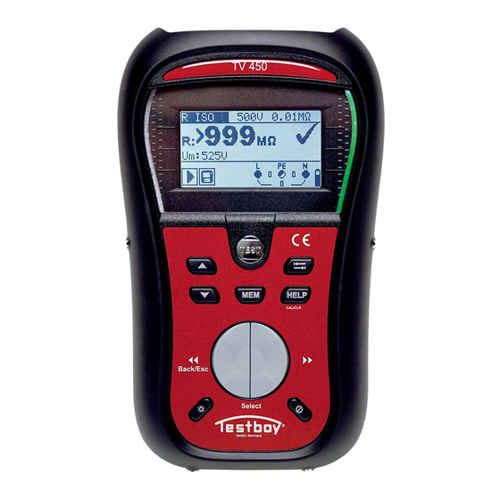
User Manuals: Testboy TV 450 Installation Tester
Manuals and User Guides for Testboy TV 450 Installation Tester. We have
3
Testboy TV 450 Installation Tester manuals available for free PDF download: Instruction Manual
Testboy TV 450 Instruction Manual (617 pages)
Brand:
Testboy
| Category:
Test Equipment
| Size: 14 MB
Table of Contents
Table of Contents
3
Sicherheits- und Betriebshinweise
6
Warnungen und Hinweise
6
Batterie und Aufladen
9
Neue oder Längere Zeit nicht Benutzte Batterien
10
Angewandte Normen
11
Vorderseite
13
Anschlussplatte
15
Rückseite
16
Aufbau des Displays
17
Klemmenspannungsüberwachung
17
Batterieanzeige
17
Feld für Meldungen
17
Ergebnisfeld
18
Akustische Warnungen
18
Hilfebildschirme
18
Einstellungen von Hintergrundbeleuchtung und Kontrast
19
Gerätesatz und Zubehör
20
Standardausstattung TESTBOY TV 450/455
20
Optionales Zubehör
20
Funktionswahl
21
Einstellungen
22
Sprache
22
Ursprüngliche Einstellungen
23
Speicher
24
Datum und Uhrzeit
24
RCD-Norm
25
Isc Factor
26
Faktor)
26
Unterstützung für Commander-Prüfspitze
27
Spannung, Frequenz und Phasenfolge
28
Isolationswiderstand
30
Widerstand der Erdverbindung und der Potentialausgleichsverbindungen
32
R LOWΩ, Widerstandsmessung 200 Ma
32
Kontinuierliche Widerstandsmessung mit Niedrigem Strom
33
Kompensation des Widerstands der Prüfleitungen
34
Prüfen von Rcds (FI-Schalter)
36
Berührungsspannung (RCD-Uc)
37
Auslösezeit (Rcdt)
38
Auslösestrom (RCD I)
39
Automatische RCD-Prüfung
40
Fehlerschleifenimpedanz und Unbeeinflusster Fehlerstrom
43
Leitungsimpedanz und Unbeeinflusster Kurzschlussstrom/Spannungsfall
45
Leitungsimpedanz und Unbeeinflusster Kurzschlussstrom
46
Spannungsfall
47
Erdungswiderstand
50
PE-Prüfklemme
52
Speicherorganisation
54
Datenstruktur
54
Speichern von Prüfergebnissen
56
Abrufen von Prüfergebnissen
56
Löschen Gespeicherter Daten
58
Löschen des Gesamten Speicherinhalts
58
Löschen von Messung(En) an der Ausgewählten Speicherstelle
58
Löschen Einzelner Messungen
59
Umbenennen von Infrastrukturelementen
60
Kommunikation
61
Wartung
63
Austausch der Sicherung
63
Reinigung
63
Regelmäßige Kalibrierung
63
Kundendienst
63
Technische Daten
64
Isolationswiderstand
64
Durchgang
65
Niederohm-Widerstand R LOW
65
Durchgangswiderstand
65
RCD-Prüfung
65
Allgemeine Daten
65
Berührungsspannung RCD-Uc
66
Auslösezeit
66
Auslösestrom
67
Fehlerschleifenimpedanz und Unbeeinflusster Fehlerstrom
67
Keine Trenneinrichtung oder Sicherung Ausgewählt
67
RCD Gewählt
68
Leitungsimpedanz und Unbeeinflusster Kurzschlussstrom/Spannungsfall
68
Erdungswiderstand
70
Spannung, Frequenz und Phasendrehung
70
Phasendrehung
70
Spannung
70
Frequenz
70
Ständige Klemmenspannungsüberwachung
71
Allgemeine Daten
71
Sicherungstabelle - IPSC
72
Sicherungstabelle - Impedanzen (GB)
74
Liste der Länderbezogenen Änderungen
77
Änderungspunkte
77
Österreich- Unterstützung der RCD-Typ G
77
Schweiz- Unterstützung der Rcds I N = 15 Ma
78
Allgemeine Daten
79
Preface
85
Safety and Operational Considerations
86
Warnings and Notes
86
Battery and Charging
89
New Battery Cells or Cells Unused for a Longer Period
90
Standards Applied
91
Instrument Description
92
Front Panel
92
Connector Panel
94
Back Side
95
Display Organization
96
Terminal Voltage Monitor
96
Battery Indication
96
Message Field
96
Result Field
97
Sound Warnings
97
Help Screens
97
Backlight and Contrast Adjustments
98
Instrument Set and Accessories
99
Standard Set TV 450/455
99
Optional Accessories
99
Instrument Operation
100
Function Selection
100
Settings
101
Language
101
Initial Settings
102
Memory
103
Date and Time
103
RCD Standard
104
Isc Factor
105
Commander Support
105
Measurements
107
Voltage, Frequency and Phase Sequence
107
Insulation Resistance
109
Resistance of Earth Connection and Equipotential Bonding
111
R LOWΩ, 200 Ma Resistance Measurement
112
Continuous Resistance Measurement with Low Curren
113
Compensation of Test Leads Resistance
113
Testing Rcds
115
Contact Voltage (RCD Uc)
116
Trip-Out Time (Rcdt)
117
Trip-Out Current (RCD I)
118
RCD Autotest
119
Fault Loop Impedance and Prospective Fault Current
122
Line Impedance and Prospective Short-Circuit Current / Voltage Drop
124
Line Impedance and Prospective Short Circuit Current
125
Voltage Drop
126
Earth Resistance
129
PE Test Terminal
131
Data Handling
133
Memory Organization
133
Data Structure
133
Storing Test Results
135
Recalling Test Results
136
Clearing Stored Data
137
Clearing Complete Memory Content
137
Clearing Measurement(S) in Selected Location
137
Clearing Individual Measurements
138
Renaming Installation Structure Elements
139
Communication
140
Upgrading the Instrument
141
Maintenance
142
Fuse Replacement
142
Cleaning
142
Periodic Calibration
142
Service
142
Technical Specifications
143
Insulation Resistance
143
Continuity
144
Resistance R LOW
144
Resistance CONTINUITY
144
RCD Testing
144
General Data
144
Contact Voltage RCD-Uc
145
Trip-Out Time
145
Trip-Out Current
145
Fault Loop Impedance and Prospective Fault Current
146
No Disconnecting Device or FUSE Selected
146
RCD Selected
147
Line Impedance and Prospective Short-Circuit Current / Voltage Drop
147
Resistance to Earth
149
Voltage, Frequency, and Phase Rotation
149
Phase Rotation
149
Voltage
149
Frequency
149
Online Terminal Voltage Monitor
150
General Data
150
A Appendix A - Fuse Table
151
Fuse Table - IPSC
151
Fuse Table - Impedances (UK)
153
B Appendix B - Accessories for Specific Measurements
155
C Appendix F - Country Notes
156
List of Country Modifications
156
Modification Issues
156
AT Modification - G Type RCD
156
Prefacio
164
Consideraciones Operativas y de Seguridad
165
Advertencias y Notas
165
Batería y Carga
168
Normas Aplicadas
170
Descripción del Instrumento
171
Panel Frontal
171
Panel de Conexiones
173
Parte Trasera
174
Organización de la Pantalla
175
Indicación de Batería
175
Campo de Mensaje
175
Campo de Resultado
176
Avisos Sonoros
176
Pantallas de Ayuda
176
Ajustes de Retroiluminación y Contraste
177
Instrumental y Accesorios
178
Accesorios Opcionales
178
Funcionamiento de Los Instrumentos
179
Selección de Funciones
179
Ajustes
180
Idioma
180
Ajustes Iniciales
181
Memoria
182
Fecha y Hora
182
Factor Isc
184
Medidas
186
Tensión, Frecuencia y Secuencia de Fases
186
Resistencia de Aislamiento
188
Resistencia de la Conexión a Tierra y de la Conexión Equipotencial
190
Compensación de la Resistencia de Los Cables de Prueba
192
Tensión de Contacto (RCD Uc)
195
Tiempo de Desconexión (Rcdt)
196
Corriente de Desconexión (RCD I)
197
Autotest RCD
198
Impedancia del Bucle de Defecto y Corriente de Defecto Prevista
201
Impedancia de Línea y Corriente de Cortocircuito Prevista / Caída de Tensión
203
Impedancia de Línea y Corriente de Cortocircuito Prevista
203
Caída de Tensión
203
Resistencia a Tierra
208
Terminal de Prueba PE
210
Tratamiento de Datos
212
Organización de la Memoria
212
Estructura de Los Datos
212
Almacenamiento de Los Resultados de las Pruebas
214
Recordar Los Resultados de las Pruebas
215
Borrar Datos Almacenados
216
Borrar todo el Contenido de la Memoria
216
Renombrar Elementos de la Estructura de la Instalación
218
Comunicación
219
Actualización del Instrumento
220
Mantenimiento
221
Sustitución de Fusibles
221
Limpieza
221
Calibración Periódica
221
Servicio
221
Especificaciones Técnicas
222
Resistencia de Aislamiento
222
Continuidad
223
Resistencia R
223
Pruebas RCD
223
Datos Generales
223
Tensión de Contacto RCD-Uc
224
Corriente de Desconexión
225
Impedancia del Bucle de Defecto y Corriente de Defecto Prevista
225
Sin Dispositivo de Desconexión O FUSIBLE Seleccionado
225
RCD Seleccionado
226
Impedancia de Línea y Corriente de Cortocircuito Prevista / Caída de Tensión
226
Resistencia a Tierra
227
Tensión, Frecuencia y Rotación de Fases
227
Rotación de Fases
227
Tensión
227
Frecuencia
227
Datos Generales
228
Apéndice A - Tabla de Fusibles
229
Tabla de Fusibles - IPSC
229
Apéndice B - Accesorios para Mediciones Específicas
233
Apéndice F - Notas por Países
235
Lista de Modificaciones por País
235
Manuel D'instruction
238
Préface
242
Sécurité et Considérations Opérationnelles
243
Avertissements et Notes
243
Batterie et Charge
246
Éléments de Batterie Neufs ou Inutilisés pendant une Période Prolongée
247
Normes Appliquées
248
Description de L'instrument
249
Panneau Avant
249
Panneau de Connexion
251
Panneau des Connecteurs
251
Face Arrière
252
Organisation de L'affichage
253
Contrôle de la Tension aux Bornes
253
Indication de la Batterie
253
Champ de Résultat
254
Avertissements Sonores
254
Instrumentation et Accessoires
256
Ensemble Standard TV 450/455
256
Accessoires en Option
256
Fonctionnement de L'instrument
257
Sélection des Fonctions
257
Réglages
258
Langue
258
Mémoire
259
Date et Heure
260
Facteur Isc
262
Mesures
264
Tension, Fréquence et Ordre des Phases
264
Résistance D'isolation
266
Compensation de la Résistance des Fils D'essai
270
Test des DDR
272
Tension de Contact (RCD Uc)
273
Temps de Déclenchement (Rcdt)
274
Courant de Déclenchement (RCD I)
275
Autotest RCD
276
Impédance de Ligne et Courant de Court-Circuit Potentiel / Chute de Tension
281
Impédance de Ligne et Courant de Court-Circuit Potentiel
282
Chute de Tension
283
Résistance à la Terre
286
Borne de Test PE
288
Traitement des Données
290
Organisation de la Mémoire
290
Structure des Données
290
Stockage des Résultats des Tests
292
Rappel des Résultats des Tests
293
Effacer les Données Enregistrées
294
Effacement de Mesure(S) à L'endroit Sélectionné
294
Effacer des Mesures Individuelles
294
Renommer les Éléments de la Structure D'installation
295
Communication
296
Mise à Niveau de L'instrument
296
Entretien
297
Remplacement des Fusibles
297
Nettoyage
297
Étalonnage Périodique
297
Service
297
Spécifications Techniques
298
Résistance D'isolation
298
Continuité
299
Résistance R
299
Résistance CONTINUITÉ
299
Données Générales
299
Tension de Contact RCD-Uc
300
Temps de Déclenchement
300
Courant de Déclenchement
300
Impédance de la Boucle de Défaut et Courant de Défaut Prospectif
301
Pas de Dispositif de Déconnexion ou FUSE Sélectionné
301
RCD Sélectionné
302
Impédance de Ligne et Courant de Court-Circuit Potentiel / Chute de Tension
302
Résistance à la Terre
303
Tension, Fréquence et Rotation des Phases
303
Fréquence
303
Contrôle en Ligne de la Tension aux Bornes
304
Données Générales
304
Annexe A - Tableau des Fusibles
305
Tableau des Fusibles - IPSC
305
Annexe B - Accessoires pour Mesures Spécifiques
309
Annexe F - Notes Par Pays
310
Liste des Modifications Apportées aux Pays
310
Modification at - RCD de Type G
310
Manuale DI Istruzioni
313
Prefazione
318
Considerazioni Sulla Sicurezza E Sull'operatività
319
Avvertenze E Note
319
Batteria E Ricarica
322
Celle Nuove O Inutilizzate Per un Lungo Periodo DI Tempo
323
Standard Applicati
324
Descrizione Dello Strumento
325
Pannello Frontale
325
Pannello Dei Connettori
327
Lato Posteriore
328
Organizzazione del Display
329
Monitoraggio Della Tensione Dei Terminali
329
Indicazione Della Batteria
329
Campo del Messaggio
329
Schermate DI Aiuto
330
Regolazione Della Retroilluminazione E del Contrasto
331
Set DI Strumenti E Accessori
332
Set Standard TV 450/455
332
Accessori Opzionali
332
Funzionamento Dello Strumento
333
Selezione Della Funzione
333
Impostazioni
334
Lingua
334
Impostazioni Iniziali
335
Memoria
336
Data E Ora
336
Standard RCD
337
Fattore Isc
338
Misure
340
Tensione, Frequenza E Sequenza DI Fase
340
Resistenza DI Isolamento
342
Resistenza del Collegamento a Terra E del Collegamento Equipotenziale
344
R LOWΩ, Misura DI Resistenza 200 Ma
345
Compensazione Della Resistenza Dei Puntali
346
Test Degli RCD
348
Tensione DI Contatto (RCD Uc)
349
Tempo DI Intervento (Rcdt)
350
Corrente DI Sgancio (RCD I)
351
Autotest RCD
352
Impedenza Dell'anello DI Guasto E Corrente DI Guasto Prospettica
355
Impedenza DI Linea E Corrente DI Cortocircuito Potenziale / Caduta DI Tensione
357
Impedenza DI Linea E Corrente DI Cortocircuito Potenziale
357
Caduta DI Tensione
357
Resistenza DI Terra
362
Terminale DI Prova PE
364
Gestione Dei Dati
366
Organizzazione Della Memoria
366
Struttura Dei Dati
366
Memorizzazione Dei Risultati Dei Test
368
Richiamo Dei Risultati Dei Test
369
Cancellazione Dei Dati Memorizzati
370
Cancellazione del Contenuto Completo Della Memoria
370
Cancellazione Delle Misure Nella Posizione Selezionata
370
Cancellazione DI Singole Misure
371
Rinominare Gli Elementi Della Struttura DI Installazione
372
Comunicazione
373
Aggiornamento Dello Strumento
373
Manutenzione
374
Sostituzione Dei Fusibili
374
Pulizia
374
Calibrazione Periodica
374
Servizio
374
Specifiche Tecniche
375
Resistenza DI Isolamento
375
Continuità
376
Resistenza R
376
Test RCD
376
Dati Generali
376
Tensione DI Contatto RCD-Uc
377
Corrente DI Sgancio
378
Impedenza Dell'anello DI Guasto E Corrente DI Guasto Prospettica
378
Nessun Dispositivo DI Disconnessione O FUSE Selezionato
378
RCD Selezionato
379
Impedenza DI Linea E Corrente DI Cortocircuito Potenziale / Caduta DI Tensione
379
Resistenza a Terra
380
Tensione, Frequenza E Rotazione DI Fase
380
Rotazione DI Fase
380
Tensione
380
Frequenza
380
Monitoraggio Online Della Tensione Dei Terminali
381
Dati Generali
381
Appendice A - Tabella Dei Fusibili
382
Tabella Dei Fusibili - Impedenze (UK)
384
Appendice B - Accessori Per Misure Specifiche
386
Appendice F - Note Sul Paese
387
Elenco Delle Modifiche Ai Paesi
387
Problemi DI Modifica
387
Inhoudsopgave
393
Voorwoord
394
Veiligheid en Operationele Overwegingen
395
Waarschuwingen en Opmerkingen
395
Batterij en Opladen
398
Nieuwe Batterijcellen of Cellen die Langere Tijd Niet Zijn Gebruikt
399
Toegepaste Normen
400
Beschrijving Instrument
401
Voorpaneel
401
Achterkant
404
Organisatie Van Het Scherm
405
Batterij-Indicatie
405
Berichtenveld
405
Resultaatveld
406
Geluidswaarschuwingen
406
Helpschermen
406
Achtergrondverlichting en Contrast Aanpassen
407
Instrumentenset en Accessoires
408
Optionele Accessoires
408
Werking Van Het Instrument
409
Functieselectie
409
Instellingen
410
Taal
410
Oorspronkelijke Instellingen
412
Geheugen
412
Datum en Tijd
412
Isc-Factor
414
Commandant Ondersteuning
414
Spanning, Frequentie en Fasevolgorde
416
Isolatieweerstand
418
R LOWΩ, Weerstandsmeting 200 Ma
421
Compensatie Van de Weerstand Van Meetsnoeren
422
Contactspanning (RCD Uc)
425
Uitschakeltijd (Rcdt)
426
Uitschakelstroom (RCD I)
427
Automatische RCD-Test
428
Foutlusimpedantie en Verwachte Foutstroom
431
Lijnimpedantie en Verwachte Kortsluitstroom
434
Spanningsverlies
435
Aardweerstand
438
PE-Testaansluiting
440
Gegevensverwerking
442
Geheugenorganisatie
442
Gegevensstructuur
442
Testresultaten Opslaan
444
Testresultaten Oproepen
445
Opgeslagen Gegevens Wissen
446
Metingen Op Geselecteerde Locatie Wissen
446
Individuele Metingen Wissen
447
Installatiestructuurelementen Hernoemen
448
Communicatie
449
Het Instrument Upgraden
449
Onderhoud
450
Zekering Vervangen
450
Schoonmaken
450
Periodieke Kalibratie
450
Service
450
Technische Specificaties
451
Isolatieweerstand
451
Continuïteit
452
Weerstand R
452
Weerstand CONTINUITEIT
452
RCD Testen
452
Algemene Gegevens
452
Aanraakspanning RCD-Uc
453
Uitschakeltijd
453
Uitschakelstroom
454
Foutlusimpedantie en Verwachte Foutstroom
454
RCD Geselecteerd
455
Weerstand Tegen Aarde
456
Spanning, Frequentie en Fasedraaiing
456
Spanning
456
Frequentie
456
Online Klemspanningsbewaking
457
Bijlage A - Tabel Met Zekeringen
458
Tabel Met Zekeringen - IPSC
458
Tabel Met Zekeringen - Impedanties (UK)
460
Przedmowa
470
Bezpieczeństwo I Względy Operacyjne
471
Ostrzeżenia I Uwagi
471
Bateria I Ładowanie
474
Nowe Ogniwa Baterii Lub Ogniwa Nieużywane Przez Dłuższy Czas
475
Zastosowane Standardy
476
Panel Przedni
477
Panel Złączy
479
Tylna Strona
480
Organizacja Wyświetlacza
481
Monitor Napięcia Na Zaciskach
481
Wskazanie Baterii
481
Ostrzeżenia Dźwiękowe
482
Ekrany Pomocy
482
Regulacja Podświetlenia I Kontrastu
483
Zestaw PrzyrząDów I Akcesoriów
484
Akcesoria Opcjonalne
484
Działanie Urządzenia
485
Wybór Funkcji
485
Ustawienia
486
Język
486
Ustawienia Początkowe
487
Pamięć
488
Data I Godzina
488
Standard RCD
489
Współczynnik Isc
490
Pomiary
492
Napięcie, Częstotliwość I Kolejność Faz
492
Rezystancja Izolacji
494
Rezystancja Uziemienia I Wyrównanie Potencjałów
496
R LOWΩ, Pomiar Rezystancji 200 Ma
497
Kompensacja Rezystancji Przewodów Pomiarowych
499
Testowanie Wyłączników RCD
500
Napięcie Styku (RCD Uc)
501
Czas Wyłączenia (Rcdt)
502
PrąD Wyłączenia (RCD I)
503
Autotest Wyłącznika Różnicowoprądowego
504
Impedancja Linii I Spodziewany PrąD Zwarciowy / Spadek Napięcia
509
Impedancja Linii I Spodziewany PrąD Zwarciowy
510
Spadek Napięcia
511
Rezystancja Uziemienia
514
Zacisk Testowy PE
517
Obsługa Danych
519
Organizacja PamięCI
519
Struktura Danych
519
Przechowywanie Wyników Testów
521
Przywoływanie Wyników Testów
522
Czyszczenie Zapisanych Danych
523
Czyszczenie Całej ZawartośCI PamięCI
523
Czyszczenie Pomiarów W Wybranej Lokalizacji
523
Czyszczenie Poszczególnych Pomiarów
524
Zmiana Nazwy Elementów Struktury Instalacji
525
Komunikacja
526
Konserwacja
527
Czyszczenie
527
Okresowa Kalibracja
527
Usługa
527
Specyfikacja Techniczna
528
Rezystancja Izolacji
528
CIągłość
529
Opór R
529
Dane Ogólne
529
Czas Wyłączenia
530
PrąD Wyłączenia
531
Nie Wybrano Urządzenia Odłączającego Lub Bezpiecznika
531
Impedancja Linii I Spodziewany PrąD Zwarciowy / Spadek Napięcia
532
Napięcie, Częstotliwość I Rotacja Faz
533
Napięcie
533
Częstotliwość
533
Monitor Napięcia Terminala Online
534
Dodatek a - Tabela Bezpieczników
535
Tabela Bezpieczników - IPSC
535
Tabela Bezpieczników - Impedancje (UK)
537
Dodatek B - Akcesoria Do Określonych Pomiarów
539
Dodatek F - Informacje O Krajach
540
Lista Modyfikacji Krajowych
540
Kwestie Modyfikacji
540
Modyfikacja at - Wyłącznik Różnicowoprądowy Typu G
540
Innehållsförteckning
546
Förord
547
Säkerhets- Och Driftsöverväganden
548
Varningar Och Anmärkningar
548
Batteri Och Laddning
551
Nya Battericeller Eller Celler Som Inte Använts under en Längre Tid
552
Tillämpade Standarder
553
Beskrivning Av Instrumentet
554
Frontpanel
554
Baksida
557
Övervakning Av Terminalspänning
558
Batteriindikering
558
Meddelandefält
558
Resultatfält
559
Ljudvarningar
559
Hjälpskärmar
559
Justering Av Bakgrundsbelysning Och Kontrast
560
Instrumentuppsättning Och Tillbehör
561
Valfria Tillbehör
561
Instrumentets Funktion
562
Val Av Funktion
562
Inställningar
563
Språk
563
Initiala Inställningar
564
Minne
565
Datum Och Tid
565
RCD-Standard
566
Isc-Faktor
567
Mätningar
568
Spänning, Frekvens Och Fasföljd
568
Isolationsmotstånd
570
Motstånd I Jordanslutning Och Potentialutjämning
572
R LOWΩ, 200 Ma Resistansmätning
573
Kontinuerlig Resistansmätning Med Låg Strömstyrka
574
Kompensation Av Mätsladdarnas Motstånd
575
Test Av Jordfelsbrytare
576
RCD Autotest
580
Autotest Av Jordfelsbrytare
580
Felslingsimpedans Och Prospektiv FelströM
583
Spänningsfall
585
Jordmotstånd
590
PE-Testterminal
592
Organisation Av Minnet
594
Datastruktur
594
Förvaring Av Testresultat
596
Återkallande Av Testresultat
597
Rensning Av Lagrade Data
598
Rensning Av Hela Minnesinnehållet
598
Rensning Av Enskilda Mätningar
599
Byte Av Namn På Element I Installationsstrukturen
600
Kommunikation
601
Uppgradering Av Instrumentet
601
Underhåll
602
Byte Av Säkring
602
Rengöring
602
Periodisk Kalibrering
602
Service
602
Tekniska Specifikationer
603
Isolationsmotstånd
603
Kontinuitet
604
Allmänna Uppgifter
604
Kontaktspänning RCD-Uc
605
Utlösningstid
605
Felslingsimpedans Och Prospektiv FelströM
606
Ingen Frånskiljare Eller FUSE Vald
606
RCD Vald
607
Motstånd Mot Jord
608
Spänning, Frekvens Och Fasrotation
608
Fasrotation
608
Spänning
608
Frekvens
609
Online Övervakning Av Terminalspänning
609
Allmänna Uppgifter
609
Bilaga A - Säkringstabell
610
Säkringstabell - Impedanser (UK)
612
Bilaga B - Tillbehör För Specifika Mätningar
614
Bilaga F - Landsnoteringar
615
Frågor Om Modifiering
615
AT-Ändring - Jordfelsbrytare Typ G
615
Advertisement
Testboy TV 450 Instruction Manual (80 pages)
Brand:
Testboy
| Category:
Test Equipment
| Size: 1 MB
Table of Contents
Table of Contents
3
Preface
6
Safety and Operational Considerations
7
Warnings and Notes
7
Battery and Charging
10
New Battery Cells or Cells Unused for a Longer Period
11
Standards Applied
12
Instrument Description
13
Front Panel
13
Connector Panel
15
Back Side
16
Display Organization
17
Terminal Voltage Monitor
17
Battery Indication
17
Message Field
17
Result Field
18
Sound Warnings
18
Help Screens
18
Backlight and Contrast Adjustments
19
Instrument Set and Accessories
20
Standard Set TV 450/455
20
Optional Accessories
20
Instrument Operation
21
Function Selection
21
Settings
22
Language
22
Initial Settings
23
Memory
24
Date and Time
24
RCD Standard
25
Isc Factor
26
Commander Support
26
Measurements
28
Voltage, Frequency and Phase Sequence
28
Insulation Resistance
30
Resistance of Earth Connection and Equipotential Bonding
32
R LOWΩ, 200 Ma Resistance Measurement
33
Continuous Resistance Measurement with Low Curren
34
Compensation of Test Leads Resistance
34
Testing Rcds
36
Contact Voltage (RCD Uc)
37
Trip-Out Time (Rcdt)
38
Trip-Out Current (RCD I)
39
RCD Autotest
40
Fault Loop Impedance and Prospective Fault Current
43
Line Impedance and Prospective Short-Circuit Current / Voltage Drop
45
Line Impedance and Prospective Short Circuit Current
46
Voltage Drop
47
Earth Resistance
50
PE Test Terminal
52
Data Handling
54
Memory Organization
54
Data Structure
54
Storing Test Results
56
Recalling Test Results
57
Clearing Stored Data
58
Clearing Complete Memory Content
58
Clearing Measurement(S) in Selected Location
58
Clearing Individual Measurements
59
Renaming Installation Structure Elements
60
Communication
61
Upgrading the Instrument
62
Maintenance
63
Fuse Replacement
63
Cleaning
63
Periodic Calibration
63
Service
63
Technical Specifications
64
Insulation Resistance
64
Continuity
65
Resistance R LOWΩ
65
Resistance CONTINUITY
65
RCD Testing
65
General Data
65
Contact Voltage RCD-Uc
66
Trip-Out Time
66
Trip-Out Current
66
Fault Loop Impedance and Prospective Fault Current
67
No Disconnecting Device or FUSE Selected
67
RCD Selected
68
Line Impedance and Prospective Short-Circuit Current / Voltage Drop
68
Resistance to Earth
70
Voltage, Frequency, and Phase Rotation
70
Phase Rotation
70
Voltage
70
Frequency
70
Online Terminal Voltage Monitor
71
General Data
71
A Appendix A - Fuse Table
72
Fuse Table - IPSC
72
Fuse Table - Impedances (UK)
74
B Appendix B - Accessories for Specific Measurements
76
C Appendix F - Country Notes
77
List of Country Modifications
77
Modification Issues
77
AT Modification - G Type RCD
77
Testboy TV 450 Instruction Manual (76 pages)
Brand:
Testboy
| Category:
Test Equipment
| Size: 1 MB
Table of Contents
Instruction Manual
1
Table of Contents
3
1 Preface
6
2 Safety and Operational Considerations
7
Warnings and Notes
7
Battery and Charging
10
New Battery Cells or Cells Unused for a Longer Period
11
Standards Applied
12
3 Instrument Description
13
Front Panel
13
Connector Panel
15
Back Side
16
Display Organization
17
Terminal Voltage Monitor
17
Battery Indication
17
Message Field
17
Result Field
18
Sound Warnings
18
Help Screens
18
Backlight and Contrast Adjustments
19
Instrument Set and Accessories
20
Standard Set TESTBOY TV 450
20
Standard Set TESTBOY TV 450 (TYPE B)
20
Optional Accessories
20
4 Instrument Operation
21
Function Selection
21
Settings
22
Language
22
Initial Settings
23
Memory (Model TESTBOY TV 450 (TYPE B))
24
Date and Time (Model TESTBOY TV 450 (TYPE B))
24
RCD Standard
25
Isc Factor
26
Commander Support
26
5 Measurements
28
Voltage, Frequency and Phase Sequence
28
Insulation Resistance
30
Resistance of Earth Connection and Equipotential Bonding
32
R LOWΩ, 200 Ma Resistance Measurement
33
Continuous Resistance Measurement with Low Current (Model TESTBOY TV 450 (TYPE B))
34
Compensation of Test Leads Resistance
35
Testing Rcds
36
Contact Voltage (RCD Uc)
37
Trip-Out Time (Rcdt)
38
Trip-Out Current (RCD I)
39
RCD Autotest
40
Fault Loop Impedance and Prospective Fault Current
43
Line Impedance and Prospective Short-Circuit Current
45
Earth Resistance (Model TESTBOY TV 450 (TYPE B))
47
PE Test Terminal
49
6 Data Handling (Model TESTBOY TV 450 (TYPE B))
51
Memory Organization
51
Data Structure
51
Storing Test Results
53
Recalling Test Results
54
Clearing Stored Data
55
Clearing Complete Memory Content
55
Clearing Measurement(S) in Selected Location
55
Clearing Individual Measurements
56
Renaming Installation Structure Elements
57
Communication
58
7 Upgrading the Instrument
59
8 Maintenance
60
Fuse Replacement
60
Cleaning
60
Periodic Calibration
60
Service
60
9 Technical Specifications
61
Insulation Resistance
61
Continuity
62
Resistance R LOW Ω
62
Resistance CONTINUITY (Model TESTBOY TV 450 (TYPE B))
62
RCD Testing
62
General Data
62
Contact Voltage RCD-Uc
63
Trip-Out Time
63
Trip-Out Current
63
Fault Loop Impedance and Prospective Fault Current
64
No Disconnecting Device or FUSE Selected
64
RCD Selected
65
Line Impedance and Prospective Short-Circuit Current
65
Resistance to Earth (Model TESTBOY TV 450 (TYPE B))
66
Voltage, Frequency, and Phase Rotation
66
Phase Rotation
66
Voltage
66
Frequency
66
Online Terminal Voltage Monitor
67
General Data
67
A Appendix A - Fuse Table
68
Fuse Table - IPSC
68
Fuse Table - Impedances (UK)
70
B Appendix B - Accessories for Specific Measurements
72
C Appendix F – Country Notes
73
Advertisement
Advertisement
Related Products
Testboy TV 455
Testboy TV 456
Testboy TV 470
Testboy TV 440
Testboy TV 410N
Testboy TV 430 N
Testboy TV 440N
Testboy TV 430
Testboy TV435
Testboy TV 441
Testboy Categories
Test Equipment
Measuring Instruments
Multimeter
Thermometer
Adapter
More Testboy Manuals
Login
Sign In
OR
Sign in with Facebook
Sign in with Google
Upload manual
Upload from disk
Upload from URL