Table of Contents
Advertisement
Quick Links
Advertisement
Table of Contents

Subscribe to Our Youtube Channel
Related Manuals for Minuteman max ride 26


Summary of Contents for Minuteman max ride 26
- Page 1 User Manual Max Ride 26 Rider Scrubber Disc Traction Drive...
-
Page 2: Preface
Preface This manual is furnished with each new MINUTEMAN® Max Ride 26. This provides the necessary operating and preventive maintenance instructions. Operators must read and understand this manual before operating or servicing this machine. This machine was designed to give you excellent performance and effi ciency. For best results and minimal cost, please follow the general guidelines below: ·... -
Page 3: Technical Specifi Cations
Technical Specifi cations Model MR26 Max Ride Model Max Ride 26 ECO Max Ride 26 Sport All Models Beginning with: MR26 Scrub Head Type Disc Disc Scrub Path 26 in (66 cm) 26 in (66 cm) 22 gal (83L) 22 gal (83L) -
Page 4: Table Of Contents
Table of Contents Preface......................2 To Turn on Vacuum Motor (B) ............... 14 Technical Specifi cations ................3 Operator Seat Pressure Switch ............15 Notes......................5 Electromagnetic Brake Bypass Switch ..........16 Safety Instructions ..................6 Extra Pressure Pedal (optional) ............16 Inspection .................... -
Page 5: Notes
Notes This page is intentionally left blank. -
Page 6: Safety Instructions
Operators must read and understand this manual before operating or maintaining this machine. Do not operate this machine in fl ammable or explosive areas. This machine is designed solely for scrubbing dirt and dust in an indoor environment. Minuteman does not recommend using this machine ®... -
Page 7: Inspection
Unpacking Instructions Inspection Carefully unpack and inspect your Max Ride 26 Rider Scrubber for shipping damage. Follow unpacking instructions on shipping pallet. Each unit has been tested and thoroughly inspected before shipment. Any damage is the responsibility of the delivery carrier who should be notifi... -
Page 8: Machine Overview
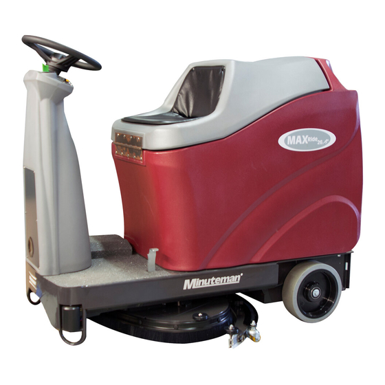
Machine Overview Machine Overview - Front STEERING WHEEL CONTROL CONSOLE ACCELERATOR PEDAL FRONT DRIVE WHEEL ROLLER BUMPER SCRUBDECK SQUEEGEE EXTRA PRESSURE PEDAL (OPTIONAL) REAR WHEEL RECOVERY AND SOLUTION TANK COMBO SOLUTION FILL PORT OPERATOR SEAT... -
Page 9: Machine Overview - Rear
Machine Overview Machine Overview - Rear RECOVERY AND SOLUTION TANK COMBO SOLUTION FILL PORT RECOVERY TANK DRAIN HOSE VACUUM MOTOR MUFFLER CIRCUIT BREAKERS ELECTROMAGNETIC BRAKE BYPASS SWITCH BATTERY COMPARTMENT SOLUTION TANK DRAIN HOSE/ SITE GAUGE REAR WHEEL SQUEEGEE SCRUBDECK ROLLER BUMPER ACCELERATOR PEDAL IGNITION SWITCH AND EMERGENCY SHUT OFF... -
Page 10: Control Panel
Machine Overview Control Panel WATER FLOW CONTROL FOWARD/REVERSE HORN PUSHBUTTON SWITCH BATTERY STATUS INDICATOR SPORT MODE INDICATOR BRUSH PUSHBUTTON VACUUM PUSHBUTTON EMERGENCY SHUTOFF KEYSWITCH... -
Page 11: Control Panel Descriptions
Machine Overview Control Panel Descriptions Solution Flow Control Switch (A) When the switch is pushed all the way forward the water is shut off . When the switch is pushed all the way down, the water is all the way on. The water pressure is variable between these two stages. -
Page 12: Circuit Breakers
Machine Overview Circuit Breakers Battery Compartment The circuit breakers are located at the bottom of the back The battery compartment is located in the rear of the machine under panel of the machine. the recovery tank. he battery compartment contains two 12-volt batteries connected in series. -
Page 13: Machine Operation
This machine was designed with total operator comfort and ease of use in mind. All machine components have been designed as a total system to effi ciently clean dirty fl oors. Please contact your Minuteman® representative for specifi c recommendations for the correct brush type, and chemical applications. -
Page 14: To Turn On Machine
Machine Operation To Turn on Machine Turn key clockwise to turn on. Wait for battery gauge to stop fl ashing. (If fl ashing continues, see troubleshooting guide) To Turn on Brush Motor (A) Lower the scrub deck to the fl oor by pushing the blue button (A) on the control panel. When the button is illuminated “blue”... -
Page 15: Operator Seat Pressure Switch
Machine Operation Operator Seat Pressure Switch The Max Ride will not operate unless the operator is sitting in the operator seat. There is a pressure switch (C) located under the operator seat that must be compressed in order for the machine to operate. There are two contact switches located on the solution/recovery tank, and the lid. -
Page 16: Electromagnetic Brake Bypass Switch
Machine Operation Extra Pressure Pedal (optional) When extra scrubbing pressure is necessary to clean up tough spots, the Max Ride has an extra pressure pedal. The pedal is located on the front of machine on the left side of the fl oorboard. Press the pedal down and forward to lock, this will apply an additional 25-30 lbs of downward pressure. -
Page 17: To Charge Batteries
Machine Operation To Charge Batteries: When the battery / fault gauge reaches the red zone the batteries need to be recharged. Take the machine to a well ventilated area, unwind the battery charger power cord from the electrical box cover and plug into an appropriate power source. After approximately 10 seconds the battery charge status indicator will turn on. -
Page 18: Loading And Unloading Brush
Machine Operation Loading and Unloading Brush Brush Unloading The brush deck must be fully raised to unload the brush, turn the ignition keyswitch to the left and hold it until the brush motor has come up to speed (approximately 4 seconds). There will be an audible sound as this happens. Release the key, and the spring return will return the key to the home position, and the brush should drop off... -
Page 19: Squeegee
Machine Operation Squeegee Cleaning the Squeegee Check the squeegee (A) daily and clean as A Squeegee necessary. B 3-sided knob 1. Pull off the suction hose. C Nut for caster height adjustment 2. loosen the two star-shaped knobs (B). D Outside Blade fastening latcfh 3. -
Page 20: Changing The Squeegee Blades
Machine Operation Changing the Squeegee Blades Check the inner and outer squeegee blades on the squeegee (A) weekly for signs of wear. The squeegee blades can be reused by turning them (can be turned for 4 total uses). It is generally easier to remove the squeegee with the brush deck in the raised position. 1. -
Page 21: Adjusting The Squeegee Blades Height Adjustment
Machine Operation Adjusting the Squeegee Blades Height Adjustment If streaks are present, the clearance between the caster wheels and fl oor must be adjusted by tightening, or loosening the nut above the bracket that holds the caster as shown in Figure A. Figure B shows optimal fl are of the squeegee for best results. -
Page 22: Solution Tank Drain Hose
Machine Operation Solution Tank Drain Hose The solution tank may be drained by removing the Solution Tank Drain Hose (A) from the Hose Clip (B) on the side of the Solution/Recovery Tank and routing the hose to a fl oor drain. Solution Level Indicator The Solution Tank Drain Hose also serves as a water level gauge for the solution tank. -
Page 23: Solution Fill Filter
Machine Operation Solution Fill Filter The Solution Fill Filter should be cleaned regularly. To remove, simply pull the fi lter out of the fi ll port on the side of the Solution/Recovery Tank, and rinse with clean water. -
Page 24: Screened Float
Machine Operation Screened Float Screened Float Removal If the recovery tank is overfi lled or a large amount of foaming is present, the screened fl oat blocks the vacuum intake inside the tank The screened fl oat is positioned inside the recovery tank protecting the vacuum motor and internal electronics from water damage. -
Page 25: Recovery Tank Drain Hose
Machine Operation Recovery Tank Drain Hose Lift cap to drain or clean out large debris In-Line Solution Filter Assembly The solution solenoid, which shuts off solution fl ow is protected from debris by the in-line fi lter assembly. The fi lter assembly is located on the under-carriage of the machine on the left hand side, just under the solution tank. -
Page 26: Care - After Use
Care - After Use After Use 1. When fi nished scrubbing, push the blue button to turn off the brush motor, and lift the scrub deck. 2. Push the orange button to stop the squeegee, and raise it off of the fl oor. Once the button is pushed, the squeegee will continue to run for an additional 8 seconds to pick up the remainder of the water off... -
Page 27: Maintenance
Maintenance Daily Weekly Monthly Yearly Charge Batteries Check Each Lubrication – Check Carbon Battery Cell(s) Grease Fittings Brushes Water Level Check/Clean Tanks Check/Clean brush & Hoses deck skirt Check/Clean the Check/Clean Brush/Pad Solution Filter Check/Clean the Squeegee Check/Clean Vacuum Shut-Off F loat in Recovery T ank Have a qualifi... -
Page 28: Troubleshooting
Recovery hose to squeegee or recovery Reconnect or replace recovery hose tank disconnected or damaged Worn brushes Rotate or replace brushes Wrong brush or cleaning chemical Consult Minuteman Debris caught on scrub brushes Remove debris Moving machine too fast Slow down Poor scrubbing performance... - Page 29 Troubleshooting Problem Possible Cause Remedy Tripped Control Power circuit breaker Reset breaker Batteries have low charge Recharge batteries Machine does not operate Battery charger operating Unplug battery charger when charge is complete Recovery tank full Empty recovery tank Excessive foaming in recovery tank. Empty recovery tank.
-
Page 31: Warranty
Warranty...
Need help?
Do you have a question about the max ride 26 and is the answer not in the manual?
Questions and answers