Table of Contents
Advertisement
Quick Links
Advertisement
Table of Contents

Related Manuals for Minuteman X Ride 28


Summary of Contents for Minuteman X Ride 28
- Page 1 User Manual X Ride 28 Riding Extractor...
-
Page 2: Introduction
If repair or maintenance work is per- common sense. . use of the X Ride 28, or uses beyond or formed on the X Ride 28, Minuteman The user's own safety, as well as the inconsistent with the X Ride’s intended... -
Page 3: Disclaimer
Introduction Disclaimer: event that technical or typographical er- Minuteman disclaims liability for any rors exist in this manual, Minuteman re- Valid as of: June 2009 personal injury, property, or other dam- serves the right to make changes to ages of any nature whatsoever, wheth- subsequent editions of this manual Minuteman International Inc. -
Page 4: Notes On Warranty
Any damage that failure to maintain and service your is the responsibility of the delivery carri- X Ride 28 in accordance with its proper er who should be notified immediately. use may void the warranty. In this re- gard, any maintenance work must be Minuteman International Inc. -
Page 5: Table Of Contents
Maintenance and Care ..32 Disposal Precautions ..12 Minuteman System Troubleshooting..48 Machine Labels ..12 Maintenance. -
Page 6: Safety Information
Safety Information Safety Information Safety and Warning Symbols All paragraphs in this manual referring to your personal safety, the safety of your machine and the environment pro- tection are attributed one of the follow- ing warning symbols: Safety Symbols Description WARNING Indicates a hazardous situation which could result in death or serious injury. -
Page 7: General Provisions
28 unit in their entirety before opera- struction plates be replaced. tion. These materials contain valu- • The X Ride 28 is designed for indoor able information regarding the safe use only. Store machine indoors. operation of the machine. Minute-... -
Page 8: Operational Precautions
Accordingly, or materials are stored or have for later disposal. use of the X Ride 28 where fire been spilled. Use of the X Ride Liquid residue remaining on the or explosion hazards may exist... -
Page 9: Maintenance Precautions
Safety Information Maintenance Precautions • Before commencing operation of the • Maintenance and repairs must be machine, check for obvious signs of performed by qualified personnel loose parts, potential conditions in- only. Maintain adjustments on ma- dicative of malfunctions, etc. Any chine pursuant to specifications not- signs of potential problems must be ed in the service manual. -
Page 10: Battery And Electrical System Precautions
• Observe all operating, use, and safe- System Precautions standards and government regula- ty instructions provided by the appro- The X Ride 28 operates on ei- tions, if any. priate battery manufacturer. ther lead acid or AGM batter- • The electrical system of the machine Used batteries must be han- ies. -
Page 11: Cleaning Solution Use And Disposal Precautions
Safety Information Cleaning Solution Use and Never dispose of the contents Disposal Precautions of the machine's recovery tank • Only cleaning agents / detergents outdoors or into stormwater suitable for automatic machines (low systems or basins! foaming) should be used in the X Ride 28. -
Page 12: Machine Labels
The following safety and information la- bels are legibly attached to the ma- chine. Replace missing or illegible labels immediately. Minuteman nameplate (Fig. 1/1) Machine identification number (Fig. 1/2) Water temp warning (Fig. 1/5) Recovery tank drain hose (Fig. 2/1) - Page 13 Safety Information General information (Fig. 1/4) A = Read and observe the instruction manual B = Maximum incline is 2 % C = Do not clean the machine by means of high-pressure cleaning equipment Fig.1 Fig.2...
-
Page 14: Machine Overview
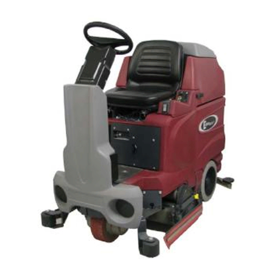
Machine Overview Machine Overview Machine Overview - Front 1 Recovery tank lid 2 Steering wheel 3 Drive wheel 4 Roller bumper 5 Foot step 6 Cylindrical deck 7 Solution level sight gauge 8 Seat adjustment lever 9 Solution tank 10 Solution tank fill port 11 Hourmeter 12 Circuit breakers Fig.3... -
Page 15: Rear
Machine Overview Machine Overview - Rear 13 Recovery tank dump hose 14 Off Aisle Wand 15 Recovery tank 16 Safety latch 17 Accelerator pedal 18 Control panel 19 Rear Wheel 20 Vacuum Shoe Fig.4... -
Page 16: Operating Elements
Operating and Indicating Elements 3 Operating and Indicating Elements Operating Panel 1 Direction selector 2 LED indicator - Forward 3 Battery / Fault gauge 4 Horn - push button 5 Key switch 6 LED indicator - Reverse 7 Interim Clean mode 8 Restorative Cleanmode 9 Off Aisle Wand mode 10 Mode selector... - Page 17 Operating and Indicating Elements Direction selector (Fig. 5/1) Mode selector(Fig. 5/10) Controls the direction in which the X Selects the operating mode of the ma- Ride 28 will move when the accelerator chine. pedal is activated. The arrow pointing Horn (Fig. 5/4) forward the amber LED (Fig.
- Page 18 Operating and Indicating Elements floor as the vacuum motor turns on pull- ing the dirty solution water from the vac- uum shoes into the recovery tank. If the machine stops moving and the direction Off Aisle Wand mode(Fig. 5/9) selector is switched to reverse, the Interim Clean mode(Fig.
-
Page 19: At The Machine
Operating and Indicating Elements At the Machine 1 Seat adjustment lever 2 Solution tank fill port 3 Solution Filter 4 Solution drain hose 5 Solution level sight gauge 6 Recovery drain hose 7 Recovery tank lid 8 Float Shut off Fig.6... - Page 20 Operating and Indicating Elements Seat adjustment lever (Fig. 6/1) Suction filter (Fig. 6/8) Use this lever to adjust the seat forward This filter protects the vacuum motor or backward. from water and debris. Solution tank fill port (Fig. 6/2) The solution tank is filled through this 1 1 1 1 port.
- Page 21 Operating and Indicating Elements Cylindrical brush hub (Fig. 7/1) This hub (both sides) can be removed to access the cylindrical brushes. The cylindrical brushes may be easily re- moved without tools. Fig.7...
- Page 22 Operating and Indicating Elements Off aisle wand tool The X Ride 28 is equipped with a ready- to-use built-in off-aisle wand system for use in hard to reach areas. Switch to the off-aisle wand mode (Fig. 5/9), then connect the wand as shown and it is ready to use.
- Page 23 Operating and Indicating Elements...
-
Page 24: First Operation
First Operation First Operation and tanks must be free from any Start Machine leakage or damage. Proceed with the following to set the Instruction 2. Install brushes - see maintenance machine to operating mode: Only persons trained by qualified Min- chapter. -
Page 25: Operation
First Operation Operation chine forward in a straight line over- diately empty the recovery 1. Switch on the machine. lapping each path by 2 to 3 inches. tank. 2. Select one of the five available modes using the mode selector (Fig. Start moving machine immedi- 7. -
Page 26: Stop Machine
First Operation The battery/ fault gauge (Fig. Stop Machine 6. Clean the machine. 5/3) will flash to signal that the To stop cleaning, select the transport machine is almost out of pow- mode (Fig. 5/13). This will automatically Do not clean the electrical er. -
Page 27: Transporting The Machine
First Operation Transporting the machine To transport the machine, turn the key switch ON, select the transport mode, select forward or reverse, activate the accelerator pedal to start movement. Tie-down points When transporting on a vehicle or trail- er, the machine has to be secured. Tie the machine down firmly by using the front foot steps (Fig. -
Page 28: Operation
Operation Operation Method of Operation General 5.1.1 Brush Deck Brush deck (Fig. 10/1) automatically lowers when traveling with a cleaning mode selected. The brushes rotate and solution supply switches on automati- cally. When the machine stops, brushes and solution supply switch off automati- cally. -
Page 29: Recovery Tank
The battery compartment contains three 12-volt batteries connected in se- ries (Fig. 10/8). The recommended bat- tery is: AGM 234 Ah (Minuteman P/N 956748) 5.1.5 Drive motor The drive motor (Fig. 10/7) features dy- namic braking as well as an electro- magnetic parking brake. -
Page 30: Technical Data
Technical Data Technical Data Cylindrical brush deck Machine length Machine height Working width Surface performance theoretical 9060 ft²/h m²/h Service voltage Nominal power drive motor Nominal power vacuum motor 650x2 W 650x2 W Nominal power brush motor 2x600 W 2x600 W Number of brushes Qty. - Page 31 Technical Data Noise emission The sound pressure level measured under maximum conditions of use (LwA) according to DIN EN 60335-2-72 amounts to: 83dB (A) 83dB The sound pressure level measured (at the ear of the driver) under normal condi- tions of use (LpA) according to DIN EN 60335-2-72 amounts to: 72dB (A) 72dB Measurement inaccuracy (KpA):...
-
Page 32: Maintenance And Care
(every 250 hours of operation) bility of the machine Compliance with the recommended To be performed by qualified personnel The Minuteman System Maintenance is maintenance work will ensure that you of authorized Minuteman Service structured in separate modules and always have a reliable machine... -
Page 33: Maintenance Document
Maintenance and Care Maintenance Document Handing over System Maintenance I System Maintenance II System Maintenance I 125 operating hours 250 operating hours 375 operating hours Upgrade Workshop stamp Workshop stamp Workshop stamp Test drive Handing over to the customer Instruction carried out on: carried out on: carried out on:... -
Page 34: Maintenance Schedule
Maintenance and Care Maintenance Schedule System Maintenance Customer Maintenance intervals must be performed by the customer/operator. Interval To be performed daily weekly Fill solution tank and proceed to chemical agent dosage Charge batteries Check brush deck and clean if required Check vacuum shoe and clean if required Clean tank lid seal of the recovery tank Empty recovery tank. - Page 35 Maintenance and Care System Maintenance I The following maintenance work must be performed by an authorized Minuteman Service workshop. Interval To be performed every 125 hours of operation Check battery charger Check tank lid seal of the recovery tank and replace if required...
- Page 36 Maintenance and Care System Maintenance II The following maintenance work must be performed by an authorized Minuteman Service workshop. Interval To be performed every 250 hours of operation Perform maintenance works according to System Maintenance I Inspect steering damages and bearing slackness and replace if required...
- Page 37 Maintenance and Care System Maintenance S (Safety check) The following maintenance work must be performed by an authorized Minuteman Service workshop at least once a year. Interval To be performed every 500 hours of operation Perform maintenance works according to System Maintenance II...
-
Page 38: Battery Systems
Maintenance and Care Battery Systems 1 Battery gauge 2 Recovery tank 3 Battery connector 4 Batteries 5 Safety latch 6 Support strap 7 Battery layout/connection Handling and changing the batteries may be performed only by maintenance staff. Fig.11... -
Page 39: Charge Batteries
In case it is intended to machine operation and control batteries. change the type of battery the charger hazards (especially on inclined has to be adjusted only by Minuteman 7.4.4 Remove Batteries surfaces) and related personal contract workshops. 1. Park machine on level ground. -
Page 40: Solution Tank
Maintenance and Care Solution tank 1 Solution tank 2 Fill level sight gauge 3 Fill port 4 Solution tank drain hose 5 Pump Box Fig.12... -
Page 41: Fill Solution Tank
Maintenance and Care 7.5.1 Fill solution tank Fill solution tank (Fig. 12/1) before work or as required. Park machine on level ground. Open fill port (Fig. 12/4) and fill tank up to the maximum (1/1 marker) on 7.5.3 Solution Filter the sight gauge (Fig. -
Page 42: Recovery Tank
Maintenance and Care Recovery tank 2. Open tank lid (Fig.13/4) of the 7.6.3 Clean Suction Filter recovery tank. Check suction filter (Fig. 13/3) at daily 3. Take drain hose (Fig. 13/2) from intervals and clean if required. The 1 Recovery tank holder and empty recovery tank suction filter can be easily removed by 2 Drain hose... -
Page 43: Cylindrical Brush Deck
Maintenance and Care Cylindrical Brush Deck 7.7.1 Clean debris tray 7.7.2 Remove brushes 1 Brush deck Clean debris tray (Fig. 14/3) at daily 1. Release brush hub (Fig. 14/5) by 2 Roller bumper intervals or as required. removing the three thumbnuts. 3 Debris Tray Remove dirt hopper by lowering the 2. -
Page 44: Pump Tank In-Line Filter
Maintenance and Care Pump Tank In-line Filter Maintenance The Solution Tank Filter (B) should be cleaned regularly. To remove, turn the Shut-off Valve (C) closed by turning it clockwise. Next, twist the Filter Cap (A) counter-clockwise and pull the filter out to clean. -
Page 45: Vacuum Shoes
Maintenance and Care 7.9 Vacuum Shoes 7.9.1 Removal The dual vacuum shoes are designed 1. With the vacuum shoes in the raised to extract soiled solution from the position, turn key switch “off”. carpet. The plastic vacuum shoe lips 2. Remove vacuum shoe locking minimize damage to carpet and bracket from left side of machine by flooring. - Page 46 Maintenance and Care Notes...
- Page 47 Maintenance and Care Notes...
-
Page 48: Troubleshooting
Worn brushes Rotate or replace brushes Wrong brush or cleaning chemical Consult Minuteman Debris caught on scrub brushes Remove debris Moving machine too fast Slow down Low battery charge Recharge batteries... - Page 49 Troubleshooting Problem Possible Cause Remedy Solution tank empty Fill solution tank Inadequate solution flow or no solution to the floor Solution lines, valves, filter or spray jets Flush lines, and clean solution filter and clogged spray jets. Solution solenoid valve Clean or replace valve Machine does not run Operator seat safety switch...
-
Page 50: Fault Codes
Troubleshooting 9) Fault Codes No. of No. of Fault Fault Description Bars Flashes Code LOW BATTERY ERROR 0x2C00 LOW BATTERY ERROR2 0x2C01 SOFT BATTERY LOCKOUT OCCURRED 0x2C02 SOFT BATTERY LOCKOUT 2 OCCURRED 0x2C03 Traction MOTOR FAULT 1 0x7800 TRACTION OVER CURRENT ERROR 0x7801 SOFT TRACTION MOTOR IN FOLDBACK STATE 0x7802... - Page 51 Troubleshooting No. of No. of Fault Fault Description Bars Flashes Code SOFT BRUSH DECK ACTUATOR OVERCURRENT 0x1311 OCCURRED BRUSH DECK ACTUATOR OVERCURRENT 2 OCCURRED 0x1321 ERROR BRUSH DECK ACTUATOR POSITIVE SHORTED 0x1411 ERROR BRUSH DECK ACTUATOR NEGATIVE SHORTED 0x1412 SOFT SOLENOID 2 OVERCURRENT OCCURRED 0x1312 SOLENOID 2 OVERCURRENT 2 OCCURRED 0x1322...
- Page 52 Troubleshooting No. of No. of Fault Fault Description Bars Flashes Code SPEED POTENTIOMETER FAULT 1 0x0810 SPEED POTENTIOMETER MAX WIPER DIFFERENCE 0x0811 ERROR SPEED POTENTIOMETER MAX PULL DOWN DIFFERENCE 0x0812 ERROR SPEED POTENTIOMETER MAX PULL SAFE DIFFERENCE 0x0813 ERROR SPEED POTENTIOMETER REFERENCE ERROR 0x0814 SPEED POTENTIOMETER LO REFERENCE ERROR 0x0815...
- Page 53 Troubleshooting No. of No. of Fault Fault Description Bars Flashes Code Any faults not covered elsewhere SOLUTION TANK EMPTY 0x1318 SOFT ALARM OVERCURRENT OCCURRED 0x131C SOFT SOLUTION PUMP OVERCURRENT OCCURRED 0x1313 SOFT SOLENOID 1 OVERCURRENT OCCURRED 0x1314 BRAKE FAULT 1 0x1500 BRAKE FAULT 2 0x1501...
-
Page 54: Minuteman International Made Simple Commercial Limited Warranty
Minuteman International, Inc. warrants to the original purchaser/user that the product is free from defects in workmanship and materials under normal use. Minuteman will, at its option, repair or replace without charge, parts that fail under normal use and service when operated and maintained in accordance with the applicable operation and instruction manuals. All warranty claims must be submitted through and approved by factory authorized repair stations. - Page 55 Minuteman International Made Simple Commercial Limited Warranty If a difficulty develops with this machine, you should contact the dealer from whom it was purchased. This warranty gives you specific legal rights, and you may have other rights which vary from state to state. Some states do not allow the exclusion or limitation of special, incidental or consequential damages, or limitations on how long an implied warranty lasts, so the above exclusions and limitations may not apply to you.
- Page 56 Minuteman International Inc. · 14N845 U.S. Route 20 · Pingree Grove, Illinois 60140 · U.S.A. Phone: 630 627-6900 · Fax 630-627-1130 www.minutemanintl.com A Member of the Hako Group...
Need help?
Do you have a question about the X Ride 28 and is the answer not in the manual?
Questions and answers