
Subscribe to Our Youtube Channel
Related Manuals for Minuteman E Ride 26


Summary of Contents for Minuteman E Ride 26
-
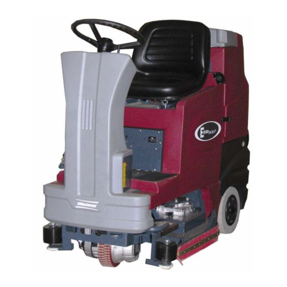
Page 1: Service Manual
Service Manual For the E Ride 26 For: Training Troubleshooting Adjustments Rev. 04/2013... -
Page 2: Table Of Contents
Contents Page 4 1 Cautions ------------------------------------------------------------------------- Page 5 2 S f t I f 2 Safety Information ------------------------------------------------------------ Page 6 3 Technical Data------------------------------------------------------------------ Page 8 4 Maintenance Intervals-------------------------------------------------------- • 4.1 Customer Maintenance K---------------------------------------------- 4.1 Customer Maintenance K Page 10 Page 10 •... - Page 3 Contents Brush Pressure Setting -------------------------------------------- Page 24 Static Chains -------------------------------------------------------- Page 25 10 1 St ti Ch i R 10.1 Static Chain Rear -------------------------------------------- Page 26 11 Service Mode -------------------------------------------------------- Page 27 12 Changing Battery Types ------------------------------------------ Page 28 13 Solution Control ----------------------------------------------------- 13 Solution Control Page 29 Page 29...
-
Page 4: Cautions
1. Cautions • Caution: • Disconnect the A.C. Cord from the outlet and and D.C. Cord from the battery pack before servicing the machine. Except for making voltage and current measurements voltage and current measurements. • After any repair work test the machine for proper operation. •... -
Page 5: F T I F 2 Safety Information
2. Safety Information Page 5... -
Page 6: Technical Data
3. Technical Data Page 6... - Page 7 3. Technical Data Page 7...
-
Page 8: Maintenance Intervals
The operator must be professionally instructed after delivery of the machine by selling dealer. •Minuteman System Maintenance I: (after every 125 hours of operation) To be preformed by an authorized Minuteman Service Center in accordance with the machine-specific system maintenance. •Minuteman System Maintenance II: (after every 250 hours of operation) - Page 9 4.1 Maintenance Intervals Record the maintenance intervals completed in the customers Operation Record the maintenance intervals completed in the customers Operation Manual, located in the battery compartment of the machine. Page 9...
-
Page 10: Customer Maintenance K
4.2 Minuteman System Maintenance K Page 10... - Page 11 4.3 Minuteman System Maintenance I Page 11...
-
Page 12: Maintenance Ii After Every 250 Hours Of Operation
4.4 Minuteman System Maintenance II Page 12... -
Page 13: Maintenance S After Every 500 Hours Of Operation, Minimum Once Per Year
4.5 Minuteman System Maintenance S (Safety Check) Page 13... -
Page 14: Squeegee Lift Mechanism
5. Squeegee Lift Mechanism Side to Side Adjustment The squeegee lift mechanism lifts and lift lift Jam Nuts (B) lowers the squeegee assembly, controls the parallel motion and pitch. Pre-adjust the bars (A) to 151mm, if parts are being replaced. Loosen the jam nuts (B) when adjusting the bar (A). -
Page 15: Squeegee Adjustment
5.1 Squeegee Adjustment Adjusting the Blades Angle Adjustment The angle adjustment is critical for insuring that the squeegee blades lie evenly on the floor. 1. Place the machine in the vacuum mode and park the machine on a level surface. 2. -
Page 16: Squeegee Caster Adjustment
5.2 Squeegee Adjustment The clearance between the support roller and floor with squeegee unfolded (Factory setting) is: 0.1181099 Inches ± 0.01968498 inches (3 mm ±0.5). Note: Some floor surfaces may require adjusting the caster washers for optimum performance. See following page. ±... - Page 17 5.2 Rear Squeegee Adjustment Page 17...
-
Page 18: Disk Side Squeegee Adjustment
7. Side Squeegee Adjustment Step 1: Lower Scrub deck by placing positioning arrow on “Double Scrub” positioning arrow on Double Scrub Double Scrub Side Squeegee is flush with floor surface Page 18... - Page 19 7. Side Squeegee Adjustment (Disk Models) Step 2: Loosen both front and rear plastic knobs. b th f ti k Page 19...
- Page 20 7. Side Squeegee Adjustment (Disk Models) Step 3: Lower Side squeegee so the squeegee squeegee so the squeegee blade flairs at the bottom around the bend and down the straight edge. •See the picture. Step 4: Re-Tighten Plastic Knobs. Page 20...
-
Page 21: Cylindrical Side Squeegee Adjustment
7. Side Squeegee Adjustment (Cyl. Models) Cylindrical Models Side Squeegees Adjustment •Place the machine in the “Double Place the machine in the Double Scrub” mode. •Loosen the two black knobs (B). •The blade should be adjusted so that it flairs on the bottom around that it flairs on the bottom around the corner and along the straight edge. -
Page 22: Cylindrical Brush Replacement
8. Cylindrical Brushes Side Squeegee Pivot •Once the yellow knob has been removed. •The side squeegee pivot (1) will swing open allowing access to the brush access place allowing access to the brush access place. •Remove the three black plastic knobs (2). Cylindrical Brush Hub •The access plate/Idler hub (3) can be removed to access the brushes. -
Page 23: Cylindrical Brush Replacement
8.1 Cylindrical Brush Replacing the Cylindrical Brush •Remove the access plate hub from the old brush. •Discard the old brush. •Stand the new brush on end with the slots on the bottom bottom. •Press the Idler hub into the top end of the new cylindrical brush. -
Page 24: Brush Pressure Setting
9. Brush Pressure Settings •The brush pressure range can be changed when changing the type of deck on the ER26 models ER26 models. •Connect the orange/violet wire into the terminal block with red/black wire group for cylindrical decks and unplug it for the disk or plate decks. -
Page 25: Static Chains
10. Static Chains Static chains on the decks, must touch the floor, when the brush deck is in the down position. They should be tested for continuity to the frame at each service interval Replace if worn or They should be tested for continuity to the frame at each service interval. Replace, if worn or damaged. -
Page 26: 10 1 St Ti Ch I R 10.1 Static Chain Rear
10.1 Static Chain •The Rear Static Chain is located between the two rear wheels. •It should be present and must always drag on the must always drag on the floor. •It should have continuity to the frame. Page 26... -
Page 27: Service Mode
11. Service Mode •The Service mode switch is located on the operators right side behind the metal panel below the seat. •The Service mode switch can be used to lower the deck when used to lower the deck when servicing the brush deck assembly. •Press and hold the lower side of the switch for 15 seconds. -
Page 28: Changing Battery Types
12. Changing Battery Types •When changing from the wet lead acid type to gel or agm batteries. The trio controller will need to be replaced with part number 748270, in order to obtain maximum run time. Gel batteries can discharged to a lower voltage level than wet lead acid batteries. -
Page 29: Solution Control
13. Solution Control •The pump box is located in the lower rear t d i th l area of the solution tank. •Drain the recovery (dirty water) tank. •Release the rubber latches on the recover tank and tilt back to access the pump box. Pump Box •The pump box includes the solution filter, l ti... -
Page 30: Trouble Shooting
14. Trouble Shooting (Electrical) Trouble Shooting Electrical Problems on the E Ride 26 • The E Ride uses a state of the art electronic circuitry with several diagnostic features. The battery indicator serves two purposes. • They are: a. To display the charge status of the batteries on the LED display. This uses 10 LED bars, for... -
Page 31: Error Code Decal
14.1 Error Code Decal Page 31... -
Page 32: Error Codes
14.2 Error Codes Single flash Low Batteries Charge the batteries Single flash Low Batteries- Charge the batteries Single flash Traction drive motor disconnected Single flash - Brush motor disconnected Single flash - Brush actuator overload Two flash – Squeegee actuator overload Page 32... - Page 33 14.2 Error Codes Single flash – Vacuum motor disconnected Single flash – Vacuum motor disconnected Single flash Off Isle Wand Activated Single flash- Off Isle Wand Activated Single flash- Potentiometer Fault l fl Single flash Control fault check all connections to Single flash- Control fault check all connections to controller- see “Trouble Shooting the Code 8 Error”...
- Page 34 14.2 Error Codes Single flash- Solution tank empty- Riders only l fl h S l ti Five flash-Electric brake circuit fault- Check all connections to the brake on the chassis drive. Single flash- High battery voltage- Loose Connection Check all connections between the batteries and the controller, including the circuit breaker.
-
Page 35: Error 8
14.3 Code 8 Error 1. Check for loose or burnt connections on the controller, batteries, cables and the circuit breaker. 2. Make the sure the circuit breaker is not damaged. 3. Measure the total battery voltage at the batteries and at the battery connections on the controller. They should be exactly the same. -
Page 36: Throttle Potentiometer
14.4 Throttle Potentiometer • Testing the Potentiometer The throttle potentiometer resistance can be measured with an ohmmeter. Unplug the throttle potentiometer at the connector next to it Unplug the throttle potentiometer at the connector next to it. Analog type meters are recommended for this test. Measuring across the black and white wires on the potentiometer, the resistance should be zero ohms with pedal on the riders in the neutral position in the full counterclockwise position. - Page 37 14.4 Potentiometer • 8. If they do not find a problem here, have them retest at the connector at the Trio controller. Reconnect the plug at the throttle potentiometer. • 9. Unplug the P3 connector (The large white connector) on the controller below the seat, behind the rear panel. th P3 (Th l t ll...
-
Page 38: Mechanical
14.5 Trouble Shooting (Mechanical Problems) Problem Possible Causes Solution The brush puts down too much The brush puts down too much Worn brushes Worn brushes Replace the brushes if worn Replace the brushes if worn pressure The brush puts down too much The belt is slipping or broken Inspect the belt and bearings pressure... -
Page 39: Lubrication Points
15. Lubrication Points L b i Lubrication Squeegee Mechanism Lubrication Points Page 39... -
Page 40: Carbon Brushes
16. Carbon Brushes • Replace the carbon brushes on or before on the following: • Vacuum Motor at 1000 hours of operation • Brush Motors (all) at 2000 hours of operation • Chassis Drive Motor 3000 hours of operation Page 40... -
Page 41: Circuit Breakers
17. Circuit Breakers Breaker # Breaker # Description Description 100 Amp Main Circuit Breaker 3 Amp for Accessories Only 18 Amp Brush Motor 1 Cylindrical Only 18 Amp Brush Motor 2 Cylindrical Only Note Disk models do not have circuit breakers 3 and 4 Page 41... -
Page 42: Electric Brake
18. Electric Brake • The chassis drive motor uses a electric brake system. • The lever can be used to unlock the brake, in the event the machine can not move on it’s own power When the brake is released the machine will be easier to push it s own power. - Page 43 18. Electric Brake Wedging the Brake •If the machine needs to be moved manually. •The brake can be disengaged by disengaged by putting a wedge or a small screwdriver (shown) behind lever arm to hold it lever arm to hold it away from the brake body.
- Page 44 18. Electric Brake Maintenance & Adjustment •The Electric brake must be checked periodically. •Clean the electric brake by using high pressure air to remove dust and dirt. •Verify the metal disk in the brake moves when pulling the arm away from the brake •Verify the metal disk in the brake moves when pulling the arm away from the brake with a small amount of pressure.
- Page 45 18.1 Electric Brake Disk Electric Brake Adjustment The brake disk, named plastic rotor must be changed when it reaches 50% wear. (When new, the rotor has a thickness of 2+2 mm; must be changed when it reaches to 1+1 mm thickness.) Note: The electric brake will work at 70%of battery power (25.2 volts) and at 70°-80°C (158-176°F)
- Page 46 18.2 Electric Brake Maintenance & Adjustment Re‐install the plastic water protection cap part water protection cap part number 241400C. Install the rubber seal (not shown) around the outside of the brake. Page 48...
-
Page 47: Notes
19. Notes Page 49...
Need help?
Do you have a question about the E Ride 26 and is the answer not in the manual?
Questions and answers