Table of Contents
Advertisement
Harbor Breeze ® is a registered trademark
of LF, LLC. All Rights Reserved.
ATTACH YOUR RECEIPT HERE
Serial Number
Questions, problems, missing parts? Before returning to your retailer, call our customer
service department at 1-800-643-0067, 8 a.m. - 6 p.m., EST, Monday - Thursday, 8 a.m. - 5
p.m., EST, Friday.
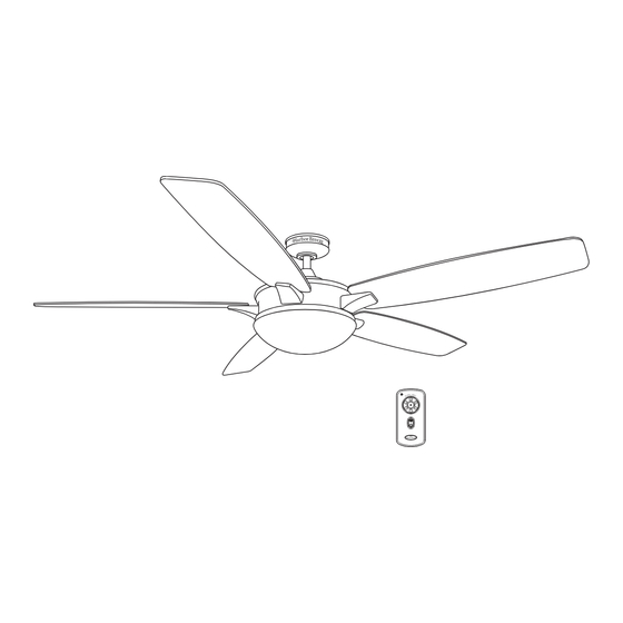
KINGSBURY CEILING FAN
Purchase Date
1 1
ITEM #0184428
MODEL #Casual-3-2011
Español p. 19
8010 · 06/29/11
Advertisement
Table of Contents

Related Manuals for Harbor Breeze Casual-3-2011


Summary of Contents for Harbor Breeze Casual-3-2011
- Page 1 ITEM #0184428 KINGSBURY CEILING FAN MODEL #Casual-3-2011 Harbor Breeze ® is a registered trademark of LF, LLC. All Rights Reserved. Español p. 19 ATTACH YOUR RECEIPT HERE Serial Number Purchase Date Questions, problems, missing parts? Before returning to your retailer, call our customer service department at 1-800-643-0067, 8 a.m.
-
Page 2: Table Of Contents
TABLE OF CONTENTS Package Contents ............. . . Hardware Contents. -
Page 3: Package Contents
PACKAGE CONTENTS PART DESCRIPTION QUANTITY PART DESCRIPTION QUANTITY Downrod Canopy Cover Canopy Light Kit Plate Mounting Bracket Remote Control Light Kit Fitter Motor Assembly Yoke Cover Blade Arm Blade Glass Shade Bulb... -
Page 4: Hardware Contents
HARDWARE CONTENTS (shown actual size) Motor Blade Blade Wire Screw Screw Washer Connector Qty. 10 Qty. 15 Qty. 15 Qty. 4 and 1 extra and 1 extra and 1 extra... -
Page 5: Safety Information
SAFETY INFORMATION Please read and understand this entire manual before attempting to assemble, operate or install the product. 1. Before you begin installing the fan, disconnect the power by removing fuses or turning off circuit Breakers. CAUTION: Read all instructions and safety information before installing your new fan. Review the accompanying assembly diagrams. -
Page 6: Preparation
WARNING WARNING speed control device or control fan speed with a full range dimmer switch. WARNING blade arms when installing them, balancing the blades, or cleaning the fan. Do not insert objects between the rotating fan blades. WARNING: To reduce the risk of personal injury, use only parts provided with this fan. The use of parts OTHER than those provided with this fan will void the warranty. -
Page 7: Assembly Instructions
ASSEMBLY INSTRUCTIONS 1. Turn off circuit breakers and wall switch to the fan supply line leads. [Fig. 1] DANGER: Failure to disconnect power supply prior to installation may result in serious injury or death. 2. Determine mounting methods to use. [Fig. 2] Important: If using the angle mount, check to make sure the ceiling angle in not steeper than 25°... - Page 8 ASSEMBLY INSTRUCTIONS 4. Secure mounting bracket (C) to outlet box using screws, box (not included). [Fig. 4] Note: It is very important that you use the proper hardware when installing the mounting bracket (C) as this will support the fan. Important: If using the angle mount, make sure open end of mounting bracket (C) is installed facing the higher point of ceiling.
- Page 9 ASSEMBLY INSTRUCTIONS 7. Slip downrod (A) into motor housing yoke, align holes and re-install pin and clip. Re-tighten set screws in motor housing yoke and then tighten nuts. Slide yoke cover (F) down until it rests on top of motor housing (E). [Fig.
-
Page 10: Wiring
ASSEMBLY INSTRUCTIONS 10. Install ball end of downrod (A) into mounting bracket (C) opening. Align slot in ball with tab in mounting bracket (C). [Fig. 10] DANGER: Failure to align slot in ball with tab may result in serious injury or death. Ball WIRING WARNING... -
Page 11: Final Installation
WIRING 2. Wrap electrical tape around each individual wire connector (DD) down to the wire as shown in Fig. 3. WARNING: Make sure no bare wire or wire strands are visible after making connections. Place green and white connections on opposite side of box from the black and blue (if applicable) connections. - Page 12 FINAL INSTALLATION 3. Insert two motor screws (AA), along with lock washers, through one blade arm, (G) to attach blade arm, (G) to motor. Tighten motor screws (AA) securely. [Fig. 3] Repeat with remaining blade arms (G), making sure to completely secure each blade arm (G) before proceeding with the next step.
- Page 13 FINAL INSTALLATION 6. Install bulbs (J). [Fig. 6] Important: When you need to replace bulbs, please allow bulb (J) and light kit to cool down before touching the bulb (J) or the light kit. Note: fan uses two 13-watt max. GU24 bi-pin base CFL bulbs WARNING: The CFL bulbs contain mercury, discard then according to the local law.
-
Page 14: Operating Instructions
OPERATING INSTRUCTIONS Remote control (M) functions: 1. Fan speed control button: To control the ceiling fan speed 1-6 2. Fan off button: To turn the fan off. 3. Reverse function button: To control fan direction. 4. Lighting control button: To control light on and off. Front 5. - Page 15 OPERATING INSTRUCTIONS WARNING responsible for compliance could void the user’s authority to operate the equipment. NOTE: This equipment has been tested and found to comply with the limits for a Class B digital device, pursuant to Part 15 of the FCC Rules. These limits are designed to provide reasonable protection against harmful interference in a residential installation.
-
Page 16: Care And Maintenance
CARE AND MAINTENANCE At least twice each year, lower canopy to check down rod assembly, and then tighten all screws on blades with a lint-free cloth. You may occasionally apply a light coat of furniture polish to wood blades for ass protection. Important: Shut off main power supply before beginning and maintenance. Do not use water or a damp cloth to clean the ceiling fan. -
Page 17: Limited Lifetime Warranty
PROBLEM DESCRIPTION QUANTITY 1. Bulb(s) not installed correctly. 1. Re-install bulb(s). operated 2. Wires in canopy not wired 2. Check wires in canopy and, if necessary, but lights properly. re-wire according to wiring instructions on fail (if pages 9 and page 10. applicable). -
Page 18: Replacement Parts List
REPLACEMENT PARTS LIST For replacement parts, call customer service department at 1-800-643-0067, 8 a.m. - 6 p.m., EST, Monday - Thursday, 8 a.m. - 5 p.m., EST, Friday. PART DESCRIPTION PART Downrod 13500104704200 Canopy 13500104702100 Mounting Bracket 13500104701200 Light Kit Fitter 13500104723200 Yoke Cover 13500104734200...
Need help?
Do you have a question about the Casual-3-2011 and is the answer not in the manual?
Questions and answers