Advertisement
Table of Contents
Harbor Breeze® is a registered trademark of
LF, LLC. All Rights Reserved.
ATTACH YOUR RECEIPT HERE
Serial Number
Questions, problems, missing parts? Before returning to your retailer, call our customer
service department at
5 p.m., EST, Friday.
EB15412
Purchase Date
1-800-643-0067, 8 a.m. - 6 p.m., EST, Monday - Thursday, 8 a.m. -
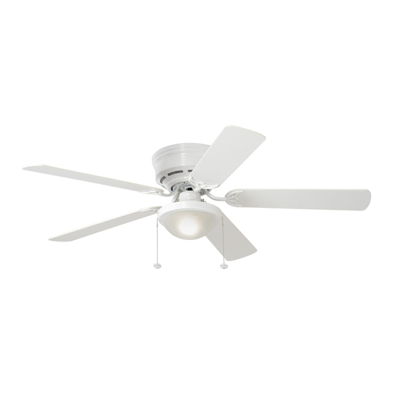
ARMITAGE CEILING FAN
Lowes.com/harborbreeze
1
ITEM #0020776
MODEL #CC52WW5C1
Español p. 18
4007498
Advertisement
Table of Contents

Related Manuals for Harbor Breeze ARMITAGE CC52WW5C1


Summary of Contents for Harbor Breeze ARMITAGE CC52WW5C1
- Page 1 ITEM #0020776 ARMITAGE CEILING FAN MODEL #CC52WW5C1 Español p. 18 Harbor Breeze® is a registered trademark of LF, LLC. All Rights Reserved. ATTACH YOUR RECEIPT HERE 4007498 Serial Number Purchase Date Questions, problems, missing parts? Before returning to your retailer, call our customer service department at 1-800-643-0067, 8 a.m.
-
Page 2: Table Of Contents
TABLE OF CONTENTS Safety Information .......................2 Package Contents .......................4 Hardware Contents ..........................5 Preparation ..........................5 Initial Installation ........................6 Wiring ..........................8 Final Installation ........................10 Operating Instructions .......................12 Care and Maintenance ......................14 Troubleshooting........................15 Limited Lifetime Warranty ....................16 Replacement Parts List .....................17 SAFETY INFORMATION READ AND SAVE THESE INSTRUCTIONS Please read and understand this entire manual before attempting to assemble, install or operate the product. - Page 3 SAFETY INFORMATION DANGER When using an existing outlet box, make sure the outlet box is securely attached to the building structure and can support the full weight of the fan. Failure to do this can result in serious injury or death.
-
Page 4: Package Contents
PACKAGE CONTENTS PART DESCRIPTION QUANTITY PART DESCRIPTION QUANTITY Mounting Bracket Mounting Bracket Nut (preassembled) Shade Fitter Plate Lock Washer Motor Housing (preassembled) + 1 extra Motor Assembly Motor Screw Glass Shade (preassembled) + 1 extra Blade Arm Motor Housing Mounting Blade Screw (preassembled) Pull Chain Extension... -
Page 5: Hardware Contents
HARDWARE CONTENTS (shown actual size) Blade Fiber Screw Blade Wire Washer Connector Qty. 15 + 1 extra Qty. 15 + 1 extra Qty. 4 PREPARATION Before beginning assembly of product, make sure all parts are present. Compare parts with package contents list and hardware contents list. -
Page 6: Initial Installation
INITIAL INSTALLATION Turn off circuit breakers and wall switch to the fan supply line leads. DANGER: Failure to disconnect power supply prior to installation may result in serious injury or death. This fan can be mounted as a flushmount on a regular (no-slope) ceiling only. - Page 7 INITIAL INSTALLATION Secure mounting bracket (A) to outlet box using screws, spring washers, and flat washers provided with the outlet box. *Note: It is very important that you use the proper hardware when installing the mounting bracket (A) as this will support the fan. Remove motor screws (M) and lock washers (L) from underside of motor -- save motor screws (M) and lock washers (L) to attach...
-
Page 8: Wiring
WIRING WARNING: To reduce the risk of fire, electrical shock, or personal injury, wire connectors provided with this fan are designed to accept only one 12-gauge house wire and two lead wires from the fan. If your house wire is larger than 12-gauge or there is more than one house wire to connect to the corresponding fan lead wires, consult an electrician for the proper size wire connectors to use. - Page 9 WIRING 1c. FAN AND LIGHT CONTROLLED BY TWO FAN AND LIGHT CONTROLLED BY TWO WALL SWITCHES FAN AND LIGHT CONTROLLED BY TWO WALL SWITCHES WALL SWITCHES: If you intend to control the BLACK (WALL SWITCH FOR LIGHT) fan and light with separate wall switches, BLACK (WALL SWITCH) connect BLACK wire from fan to BLACK wire 120 V Power...
-
Page 10: Final Installation
FINAL INSTALLATION Remove motor assembly (D) from "J" hook and lift motor assembly (D) to mounting bracket (A). Align holes and secure motor assembly (D) with mounting bracket flat washers (J) and mounting bracket nuts (K) previously removed (Step 3, page 6). Temporarily lift motor housing (C) to mounting bracket (A) to determine which two motor housing mounting screws (N) in sides of mounting bracket... - Page 11 FINAL INSTALLATION Locate motor screws (M) and lock washers (L) removed in Step 5 on page 7. Insert two motor screws (M) along with lock washers (L) through one blade arm (F) to attach blade arm (F) to motor. Tighten motor screws (M) securely.
-
Page 12: Operating Instructions
FINAL INSTALLATION Align slots on glass shade (E) with protrusions on the inside of the shade fitter plate (B). Turn glass shade (E) to the right (clockwise) until it no longer turns. NOTE: Pull down gently on the glass shade (E) to make sure that it is secured completely. - Page 13 OPERATING INSTRUCTIONS The pull chain located to the left of the reverse switch is used to turn the light ON or OFF. Use the fan reverse switch, located on the switch housing, to optimize your fan for seasonal performance. A ceiling fan will allow you to raise your thermostat setting in summer and lower your thermostat setting in winter without feeling a difference in your comfort.
-
Page 14: Care And Maintenance
OPERATING INSTRUCTIONS 3C. IMPORTANT: Reverse switch must be set 3 3C either completely UP or completely DOWN for fan to function. If the reverse switch is set in the middle position (Fig. 3C), fan will not operate. CARE AND MAINTENANCE At least twice each year, lower motor housing (C) to check motor assembly (D), and then tighten all screws on the fan. -
Page 15: Troubleshooting
TROUBLESHOOTING WARNING: Before beginning work, shut off the power supply to avoid electrical shock. PROBLEM POSSIBLE CAUSE CORRECTIVE ACTION Fan does not move. 1. Reverse switch not engaged. 1. Push switch firmly either up or down. 2. Power is off or fuse is blown. 2. -
Page 16: Limited Lifetime Warranty
LIMITED LIFETIME WARRANTY The distributor warrants this fan to be free from defects in workmanship and materials present at time of shipment from the factory for Lifetime limited from the date of purchase. This warranty applies only to the original purchaser. The distributor agrees to correct any defect at no charge or, at our option, replace the ceiling fan with a comparable or superior model. -
Page 17: Replacement Parts List
1-800-643-0067, 8 a.m. - 6 p.m., EST, Monday - Thursday, 8 a.m. - 5 p.m., EST, Friday. PART DESCRIPTION PART# 020776-A Mounting Bracket 020776-F Blade Arm 020776-G Blade Printed in China Harbor Breeze® is a registered trademark of LF, LLC. All Rights Reserved. Lowes.com/harborbreeze JMLI1508...
Need help?
Do you have a question about the ARMITAGE CC52WW5C1 and is the answer not in the manual?
Questions and answers
Where is the switch to go clockwise and counterclockwise
The switch for clockwise and counterclockwise rotation on the Harbor Breeze ARMITAGE CC52WW5C1 ceiling fan is the reverse switch, labeled as 33A, 33B, or 33C. It must be set completely UP or completely DOWN for the fan to operate. If set in the middle position, the fan will not function.
This answer is automatically generated
What amperage does the motor use