Advertisement
Table of Contents
- 1 Table of Contents
- 2 Safety Information
- 3 Package Contents
- 4 Hardware Contents
- 5 Preparation
- 6 Initial Installation
- 7 Initial Installation
- 8 Wiring
- 9 Final Installation
- 10 Installing Fan Without Included Light Kit (Optional)
- 11 Operation Instructions
- 12 Care and Maintenance
- 13 Troubleshooting
- 14 Warranty
- 15 Replacement Parts List
- Download this manual
See also:
User Manual
Harbor Breeze® is a registered trademark
of LF, LLC. All Rights Reserved.
Federal regulations require ceiling fans with light kits manufactured or imported after
January 1, 2009, to limit total wattage consumed by the light kit to 190W. Therefore,
this fan is equipped with a wattage limiting device.
ATTACH YOUR RECEIPT HERE
Serial Number
Questions, problems, missing parts? Before returning to your retailer, call our customer
service department at 1-800-527-1292, 8:30 a.m. - 5 p.m., CST,
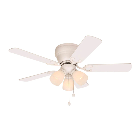
CHESHIRE II CEILING FAN
Purchase Date
1
ITEM #0317058
0317060
MODEL #CE-CSD42AB5C3
CE-CSD42LW5C3
Français p. 18
E124404
Monday-Friday.
Advertisement
Table of Contents

Related Manuals for Harbor Breeze CHESHIRE II


Summary of Contents for Harbor Breeze CHESHIRE II
- Page 1 ITEM #0317058 0317060 CHESHIRE II CEILING FAN Harbor Breeze® is a registered trademark MODEL #CE-CSD42AB5C3 of LF, LLC. All Rights Reserved. CE-CSD42LW5C3 Français p. 18 Federal regulations require ceiling fans with light kits manufactured or imported after January 1, 2009, to limit total wattage consumed by the light kit to 190W. Therefore, this fan is equipped with a wattage limiting device.
-
Page 2: Table Of Contents
TABLE OF CONTENTS Safety Information ......………………………………………………………..2 - 3 Package Contents ......…………………………………………………………..4 Hardware Contents ......…………………………………………………...5 Preparation ........….…………………..……………………….…..5 Initial Installation ..........……………………...………....6 - 8 Wiring ....................……....8 - 10 Final Installation ....………………….…………...........10 - 12 Installing Fan Without Included Light Kit (Optional) ….…............13 Operation Instructions ..........………………………....13 - 14 Care and Maintenance .......………………………..………...…..…....15... -
Page 3: Safety Information
SAFETY INFORMATION WARNINGS To reduce the risk of fire, electrical shock, or personal injury, mount fan to outlet box marked "ACCEPTABLE FOR FAN SUPPORT" and use mounting screws provided with the outlet box. Most outlet boxes commonly used for the support of lighting fixtures are not acceptable for fan support and may need to be replaced. -
Page 4: Package Contents
PACKAGE CONTENTS PART DESCRIPTION QUANTITY PART DESCRIPTION QUANTITY Extra Switch Housing Motor Housing Safety Cable Mounting Bracket (preassembled) Plastic Lock Tab Motor Housing Mounting Motor Assembly Screw (preassembled) Light Kit Fitter Motor Screw Glass Shade (preassembled) Blade Arm 5.4 M/M Lock Washer Blade (preassembled) Candelabra Base Bulb... -
Page 5: Hardware Contents
HARDWARE CONTENTS (shown actual size) Fiber Blade Screw Blade E3 Wire Washer Connector Qty. 15 Qty. 15 Qty. 4 PREPARATION Before beginning assembly and installation of product, make sure all parts are present. Compare parts with package contents list and hardware contents above. If any part is missing or damaged, do not attempt to assemble the product. -
Page 6: Initial Installation
INITIAL INSTALLATION Turn off circuit breakers and wall switch to the fan supply line leads. (Fig. 1) DANGER: Failure to disconnect power supply prior to installation may result in serious injury or death. Check to make sure blades (H) are at least 30 in. from any obstruction and at least 7 ft. - Page 7 INITIAL INSTALLATION Install ball end of motor assembly (D) into mounting bracket (B) opening. Align slot in ball with tab in mounting bracket (A). (Fig. 5) Slot DANGER: Failure to align slot in ball with tab Ball Hanging in mounting bracket (B) may result in serious injury or death.
-
Page 8: Wiring
INITIAL INSTALLATION Find a secure attachment point (wood ceiling joist highly recommended) and secure safety cable (M). It will be necessary to use a heavy duty Loop wood screw, washer and lock washer (sold Wood Joist separately) with the safety cable (M) loop. (Fig. 8) Wood Screw and Washer WIRING... - Page 9 WIRING 1B. FAN CONTROLLED BY PULL CHAIN, LIGHT FAN CONTROLLED BY PULL CHAIN, LIGHT BY WALL SWITCH BY WALL SWITCH: If you intend to control the fan light with a separate wall switch, connect BLACK BLACK wire from fan to BLACK wire from ceiling. Connect BLACK (WALL SWITCH) 120 V Power FROM...
-
Page 10: Final Installation
WIRING IMPORTANT: Using a full range dimmer switch to control fan speed will cause a loud humming noise from fan. To reduce the risk of fire or electrical shock, do NOT use a full range dimmer switch to control fan speed. (Fig. 3) Dimmer Speed Switch... - Page 11 FINAL INSTALLATION Locate motor screws (O) and 5.4 M/M lock washers (P) that were removed in Step 4 on page 6. Insert two motor screws (O), along with 5.4 M/M lock washers (P), through one blade arm (G) to attach blade arm (G) to motor.
- Page 12 FINAL INSTALLATION Remove socket ring (K) from each socket. Use one socket ring (K) to attach each glass shade (F). (Fig. 6) Note: Do not overtighten socket rings (K) as glass may crack or break. Install three candelabra base 60-watt max. bulbs (I) included.
-
Page 13: Installing Fan Without Included Light Kit (Optional)
INSTALLING FAN WITHOUT INCLUDED LIGHT KIT (OPTIONAL) If you do NOT wish to use the light kit, remove three screws from switch housing plate. (Fig. 1) Switch Housing Plate Align holes in extra switch housing (L) with holes in switch housing plate. (Note: The wide gap in the top edge of the extra switch housing (L) should align with Switch Housing... -
Page 14: Operation Instructions
OPERATION INSTRUCTIONS The pull chain in the center is used to turn the lights ON or OFF. (Fig. 2) Use the fan reverse switch, located on the light kit fitter (E), to optimize your fan for seasonal performance. (Fig. 3) A ceiling fan will allow you to raise your thermostat setting in summer and lower your thermostat setting in winter without feeling a difference in your comfort. -
Page 15: Care And Maintenance
CARE AND MAINTENANCE At least twice each year, lower motor housing (A) to check motor assembly (D), and then tighten all screws on fan. Clean motor housing (A) with only a soft brush or lint-free cloth to avoid scratching the finish. Clean blades (H) with a lint-free cloth. You may occasionally apply a light coat of furniture polish to wood blades for added protection. -
Page 16: Troubleshooting
TROUBLESHOOTING PROBLEM POSSIBLE CAUSE CORRECTIVE ACTION 4. Wires in light kit fitter (E) not 4. Check wires in light kit fitter (E) wired correctly. and, if necessary, re-wire according to instructions on page 11. 5. Light kit is lamped with more 5. -
Page 17: Replacement Parts List
REPLACEMENT PARTS LIST For replacement parts, call our customer service department at 1-800-527-1292, 8:30 a.m. - 5:00 p.m., CST, Monday - Friday. When ordering parts, please have the Model # or Item # of the fan available, which can be found on page 1. PART DESCRIPTION Motor Housing...
Need help?
Do you have a question about the CHESHIRE II and is the answer not in the manual?
Questions and answers