Advertisement
Table of Contents
- 1 Table of Contents
- 2 Safety Information
- 3 Package Contents
- 4 Hardware Contents
- 5 Preparation
- 6 Initial Installation
- 7 Downrod-Style Fan Mounting
- 8 Closemount-Style Fan Mounting
- 9 Wiring
- 10 Final Installation
- 11 Operating Instructions
- 12 Care and Maintenance
- 13 Troubleshooting
- 14 Warranty
- 15 Replacement Parts List
- Download this manual
Harbor Breeze® is a registered trademark
of LF, LLC. All Rights Reserved.
ATTACH YOUR RECEIPT HERE
Purchase Date
Questions, problems, missing parts? Before returning to your retailer, call our customer
service department at
8 a.m. - 5 p.m., EST, Friday.
PH18453
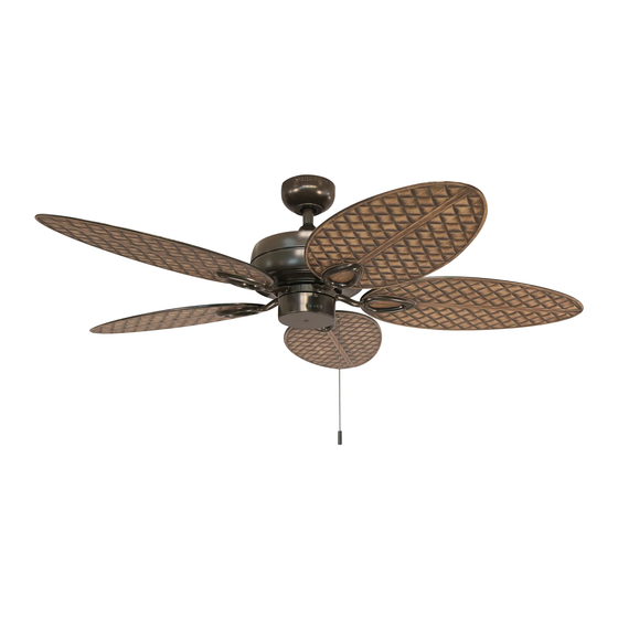
CANE BAY CEILING FAN
1-800-643-0067, 8 a.m. - 6 p.m., EST, Monday - Thursday,
1
ITEM #0883805
MODEL #WCK52NWZ5D
Español p. 19
For
Damp Location
Advertisement
Table of Contents

Related Manuals for Harbor Breeze WCK52NWZ5D


Summary of Contents for Harbor Breeze WCK52NWZ5D
- Page 1 ITEM #0883805 CANE BAY CEILING FAN MODEL #WCK52NWZ5D Harbor Breeze® is a registered trademark of LF, LLC. All Rights Reserved. Español p. 19 Damp Location ATTACH YOUR RECEIPT HERE Purchase Date Questions, problems, missing parts? Before returning to your retailer, call our customer service department at 1-800-643-0067, 8 a.m.
-
Page 2: Table Of Contents
TABLE OF CONTENTS Safety Information ....................... 2 Package Contents ....................... 4 Hardware Contents .......................... 5 Preparation ........................... 5 Initial Installation ........................5 Downrod-Style Fan Mounting ....................7 Closemount-Style Fan Mounting ..................9 Wiring ........................... 11 Final Installation ........................13 Operating Instructions ......................15 Care and Maintenance ....................... - Page 3 SAFETY INFORMATION DANGER When using an existing outlet box, make sure the outlet box is securely attached to the building structure and can support the full weight of the fan. Failure to do this can result in serious injury or death.
-
Page 4: Package Contents
PACKAGE CONTENTS PART DESCRIPTION PART DESCRIPTION QUANTITY QUANTITY Downrod Blade Canopy Blade Arm Mounting Bracket Motor Screw (preassembled) (preassembled) Motor Housing Pull Chain Extension (preassembled) Canopy Mounting Screw Yoke Cover (preassembled) Switch Housing Pin (preassembled) Clip (preassembled) IMPORTANT REMINDER: You must use the parts provided with this fan for proper installation and safety. -
Page 5: Hardware Contents
HARDWARE CONTENTS (shown actual size) Rubber Blade Blade Screw Washer Wire Connector Qty. 15 Qty. 15 + 1 extra + 1 extra Qty. 4 PREPARATION Before beginning assembly of product, make sure all parts are present. Place motor on carpet or on foam to avoid damage to finish. - Page 6 INITIAL INSTALLATION 2. Determine mounting method to use. A. Downrod mount (standard or angled ceiling) B. Closemount (standard ceiling only) IMPORTANT: If using the angle mount, check to make sure the ceiling angle is not steeper than 19°. *Helpful Hint: Downrod-style mounting is best suited for ceilings 8 ft.
-
Page 7: Downrod-Style Fan Mounting
INITIAL INSTALLATION Secure mounting bracket (C) to outlet box (not STANDARD ANGLE included) using screws, spring washers and flat MOUNT MOUNT washers provided with the outlet box. *NOTE: It is very important you use the proper hardware when installing the mounting bracket (C) as this will support the fan. - Page 8 DOWNROD-STYLE FAN MOUNTING 2. Insert downrod (A) through canopy (B) and yoke cover (E). Thread wires from motor housing (D) up through downrod (A). Slip downrod (A) into yoke, align holes and re-install pin (L) and clip (M). Tighten set screws and then tighten nuts on the set screws.
-
Page 9: Closemount-Style Fan Mounting
DOWNROD-STYLE FAN MOUNTING If you decided to cut back the lead wires in Step 4, strip 1/2 in. of insulation from end of each wire -- white, black, green and blue (if applicable). Twist stripped ends of each strand of wire within the insulation with pliers (not included). - Page 10 CLOSEMOUNT-STYLE FAN MOUNTING Remove every other preassembled screw from top of motor housing (D). 3. Pull wires up through hole in the middle of the canopy (B) and attach canopy (B) to motor housing (D) using the three screws previously removed.
-
Page 11: Wiring
WIRING WARNING: To reduce the risk of fire, electrical shock or personal injury, wire connectors provided with this fan are designed to accept only one 12-gauge house wire and two lead wires from the fan. If your house wire is larger than 12-gauge or there is more than one house wire to connect to the corresponding fan lead wires, consult an electrician for the proper size wire connectors to use. - Page 12 WIRING 1c. FAN AND LIGHT CONTROLLED BY TWO FAN AND LIGHT CONTROLLED BY TWO WALL SWITCHES FAN AND LIGHT CONTROLLED BY TWO WALL SWITCHES WALL SWITCHES: If you intend to control the fan and light with separate wall switches, connect 120V POWER BLACK wire from fan to BLACK wire from the FROM CEILING...
-
Page 13: Final Installation
FINAL INSTALLATION Lift canopy (B) to mounting bracket (C) and align slotted holes in canopy (B) with canopy mounting Downrod Closemount screws (K) loosened in Step 4a, page 6. Twist Option Option canopy (B) clockwise to lock. Re-insert the two canopy mounting screws (K) previously removed (Step 4a, page 6), then tighten all securely. - Page 14 FINAL INSTALLATION 4. Remove three preassembled screws from switch housing plate on the underside of motor housing (D). Connect male plug from motor housing (D) to female plug from switch housing (F), matching up the colors on the male plug with the colors on the female plug for Switch Housing correct fit.
-
Page 15: Operating Instructions
OPERATING INSTRUCTIONS The pull chain located on the switch housing (F) has four positions to control fan speed. One pull is HIGH, two is MEDIUM, three is LOW and four turns the fan OFF. Use the fan reverse switch, located on the switch housing (F), to optimize your fan for seasonal performance. -
Page 16: Care And Maintenance
OPERATING INSTRUCTIONS 3a. In warmer weather, setting the reverse switch in the LEFT position will result in downward airflow creating a wind chill effect. 3b. In cooler weather, setting the reverse switch in the RIGHT position will result in upward airflow that can help move stagnant, hot air off the ceiling area. -
Page 17: Troubleshooting
TROUBLESHOOTING WARNING: Before beginning work, shut off the power supply to avoid electrical shock. PROBLEM POSSIBLE CAUSE CORRECTIVE ACTION Fan does not move. 1. Reverse switch not engaged. 1. Push switch firmly either up or down. 2. Power is off or fuse is blown. 2. -
Page 18: Warranty
LIMITED LIFETIME WARRANTY The distributor warrants this fan to be free from defects in workmanship and materials present at time of shipment from the factory for Lifetime limited from the date of purchase. This warranty applies only to the original purchaser. The distributor agrees to correct any defect at no charge or, at our option, replace the ceiling fan with a comparable or superior model.
Need help?
Do you have a question about the WCK52NWZ5D and is the answer not in the manual?
Questions and answers
What is the best lighting kit and remote control for this model?
The Harbor Breeze WCK52NWZ5D model uses a light kit that requires 4 bulbs with a maximum wattage of 6.5 watts each. It is remote control adaptable, but any remote control used must be UL-approved for damp locations. No specific brand or model of light kit or remote control is recommended in the provided information.
This answer is automatically generated
Can I order the motor screws (I) for the model #Harbor Breeze Tilghman II 52-in Bronze Indoor/Outdoor Residential Ceiling Fan ?