Table of Contents
Advertisement
Harbor Breeze® is a registered trademark
of LF, LLC. All Rights Reserved.
ATTACH YOUR RECEIPT HERE
Purchase Date
Questions, problems, missing parts? Before returning to your retailer, call our customer
service department at
5 p.m., EST, Friday.
EB1717
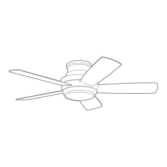
SEVERN FALLS CEILING FAN
1-800-643-0067, 8 a.m. - 6 p.m., EST, Monday - Thursday, 8 a.m. -
1
ITEM
#0835142
MODEL
#C-TMH44CH5D1R
Français p. 17
E192641
Advertisement
Table of Contents

Related Manuals for Harbor Breeze C-TMH44CH5D1R


Summary of Contents for Harbor Breeze C-TMH44CH5D1R
- Page 1 ITEM #0835142 SEVERN FALLS CEILING FAN MODEL #C-TMH44CH5D1R Harbor Breeze® is a registered trademark of LF, LLC. All Rights Reserved. Français p. 17 ATTACH YOUR RECEIPT HERE E192641 Purchase Date Questions, problems, missing parts? Before returning to your retailer, call our customer service department at 1-800-643-0067, 8 a.m.
-
Page 2: Table Of Contents
TABLE OF CONTENTS Safety Information ........................2 Package Contents ........................4 Hardware Contents ..........................5 Preparation ..........................5 Initial Installation ........................5 Installing Safety Cable ......................7 Wiring ...........................8 Final Installation ........................9 Installing Fan With Light Kit ....................11 Installing Fan Without Light Kit ...................12 Operating Instructions ......................13 Care and Maintenance .......................14 Troubleshooting .........................15 Limited Lifetime Warranty ....................16... - Page 3 SAFETY INFORMATION WARNING When mounting fan to a ceiling outlet box, use a METAL octagonal outlet box; do NOT use a plastic outlet box. Secure the outlet box directly to the building structure. The outlet box and its support must be able to support the moving weight of the fan (at least 35 lbs.). To avoid personal injury, the use of gloves may be necessary while handling fan parts with sharp edges.
-
Page 4: Package Contents
PACKAGE CONTENTS PART DESCRIPTION PART DESCRIPTION QUANTITY QUANTITY Mounting Plate Fitter Plate Screw (preassembled to Fitter Housing Ring Plate (D)) Motor Housing Mounting Plate Screw Fitter Plate (preassembled to Mounting LED Light Kit Plate (A)) Glass Shade Remote Control Receiver Metal Cover Remote Pack Blade... -
Page 5: Hardware Contents
HARDWARE CONTENTS (shown actual size) Blade Fiber Screw Blade Wire Washer Connector Qty. 15 + 1 extra Qty. 15 Qty. 9 + 1 extra PREPARATION Before beginning assembly of product, make sure all parts are present. Compare parts with package contents list and hardware contents list. - Page 6 INITIAL INSTALLATION This fan can be mounted as a flushmount on a regular (no-slope) ceiling only. Check to make sure blades (H) will be at least 30 in. 30 in. from any obstruction and at least 7 ft. above min. the floor.
-
Page 7: Installing Safety Cable
INITIAL INSTALLATION With wider opening of housing ring (B) facing up, place it over the top of motor housing (C) and Indentation align tabs inside housing ring (B) with indentations at top of motor housing (C). Then, push housing ring (B) down about 1 - 2 in. past top edge of motor housing (C). -
Page 8: Wiring
WIRING WARNING: To reduce the risk of fire, electrical shock or personal injury, each wire connector provided with this fan is designed to accept only one 12-gauge house wire and one lead wire from the fan. If your house wire is larger than 12-gauge or there is more than one house wire to connect to the corresponding fixture lead wires, consult an electrician. -
Page 9: Final Installation
WIRING 2. 2. Wrap electrical tape (not included) around each individual wire connector (CC) down to the wire. WARNING: Make sure no bare wire or wire strands are visible after making connections. Place BARE/GREEN and WHITE connections on opposite side of box from the BLACK and BLUE (if applicable) connections. - Page 10 FINAL INSTALLATION 2. Slide housing ring (B) up to top of motor housing Indentation (C), making sure to align tabs inside housing ring (B) with four indentations at top of motor housing (C). IMPORTANT: The tabs must fit snugly over the indentations to ensure a secure fit.
-
Page 11: Installing Fan With Light Kit
FINAL INSTALLATION Remove one preassembled fitter plate screw (J) from post on underside of fitter plate (D) and partially loosen the other two fitter plate screws (J). To install the fan with the light kit, proceed to INSTALLING FAN WITH LIGHT KIT below. To install the fan without the light kit, skip to INSTALLING FAN WITHOUT LIGHT KIT on page 12. -
Page 12: Installing Fan Without Light Kit
INSTALLING FAN WITH LIGHT KIT Align grooves on glass shade (F) with nodules on inside of LED light kit (E) and push up gently on glass shade (F). Turn glass shade (F) clockwise until it no longer turns. NOTE: The use of rubber grip gloves are recommended should you need to remove the glass shade (F). -
Page 13: Operating Instructions
INSTALLING FAN WITHOUT LIGHT KIT Locate slots on metal cover (G) and align with nodules inside LED light kit (E). Push up on metal cover (G) and turn clockwise until it no longer turns. Assembly is now complete. OPERATING INSTRUCTIONS CAUTION: The remote control transmitter can be programmed to multiple receivers or fans. -
Page 14: Care And Maintenance
OPERATING INSTRUCTIONS 2. Restore electrical power. Within 30 seconds of restoring electrical power, press the “OFF” button on the front of the remote control transmitter for 5 seconds or until light on the fan blinks twice. Use the remote control to test the light and fan functions to confirm the learning process is complete. -
Page 15: Troubleshooting
TROUBLESHOOTING WARNING: Before beginning work, shut off the power supply to avoid electrical shock. PROBLEM POSSIBLE CAUSE CORRECTIVE ACTION Fan does not 1. Power is off or fuse is blown. 1. Turn power on or check fuse. move. 2. Faulty wire connection. 2. -
Page 16: Limited Lifetime Warranty
LIMITED LIFETIME WARRANTY The distributor warrants this fan to be free from defects in workmanship and materials present at time of shipment from the factory for Lifetime limited from the date of purchase. This warranty applies only to the original purchaser. The distributor agrees to correct any defect at no charge or, at our option, replace the ceiling fan with a comparable or superior model.
Need help?
Do you have a question about the C-TMH44CH5D1R and is the answer not in the manual?
Questions and answers