Samson 3271 Mounting And Operating Instructions
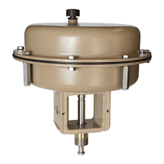
Pneumatic actuator
Hide thumbs
Also See for 3271:
- Mounting and operating instructions (76 pages) ,
- Original instructions manual (72 pages) ,
- Mounting and operating instruction (112 pages)

Related Manuals for Samson 3271


Summary of Contents for Samson 3271
- Page 1 Pneumatic Actuator Type 3271 Type 3271 Type 3271 with handwheel Type 3271-5 Type 3271-52 Fig. 1 · Type 3271 Actuators Mounting and Operating Instructions EB 8310 EN Edition October 2004...
-
Page 2: Table Of Contents
Reversing the operating direction (fail-safe action) ... . 6 2.1.1 Type 3271 ....... 6 2.1.2 Actuator with handwheel . -
Page 3: Design And Principle Of Operation
The handwheel moves the actua- tor stem over a spindle. The Type 3271 Ac- The Type 3271 Actuators are primarily used tuator can be equipped in a special version... - Page 4 21 Washer (60 cm Actuator stem extends Actuator stem retracts 22 Sleeve (60 cm Stem seal Top diaphragm case 12.1 Dry bearing Springs Fig. 3 · Type 3271-5 Actuators with 120 cm (top) and 60 cm (bottom) effective diaphragm area EB 8310 EN...
- Page 5 Design and principle of operation Actuator stem extends creased enough to overcome the force ex- erted by the springs. When the signal pressure is reduced or the air supply fails, the springs move the actua- The tandem actuator (Fig. 4) has two dia- tor stem downwards and close the valve.
-
Page 6: Operation
"Actuator stem retracts" is specified on is kept as shown in Fig. 2 and the table the nameplate with the initials FA and FE on below. Type 3271 Actuator or by a symbol on Type 3271-5 Actuator. Actuator cm Dimension a in mm (Fig. 2) 100.5, or 89 with threaded end... - Page 7 (2.1) for the mechanical travel stop. The springs which are now pressed from the In Type 3271-52 Actuator with 60 cm dia- top against the diaphragm plate cause the phragm area, unthread the screw (20) and actuator stem to extend.
-
Page 8: Actuator With Handwheel
(2.1) for the travel coupling nut (25) from the coupling stop. (22). For Type 3271-52 Actuator with 60 cm 3. Knock out the clamping sleeve (23) and undo the screw (20) and then remove the remove the ring (24). - Page 9 Operation After reversing the operating direction: 2. Attach the ring (24) with clamping sleeve (23). 1. Place the flange part (21) and the cou- 3. Screw coupling nut (25) as far as it will pling nut (25) and then secure flange go onto the coupling (22) and secure part (21) with ring nut (28).
-
Page 10: Replacing The Diaphragm And Stem Seal
2. Remove the hose clamp (8.1) and pull it together with the diaphragm (8) off the diaphragm plate (7) (not necessary with Type 3271-5 as the diaphragm is held in place by the metal plate (7.1)). 3. Stretch the new diaphragm onto the dia- phragm plate. -
Page 11: Adjusting The Travel Stop
Operation Adjusting the travel stop (Type 3271 in special version only) The travel stop can be adjusted upwards or downwards to 50 % of the travel. Downward travel stop (actuator stem extends) 1. Undo the lock nut (34) and unscrew the cap (33). -
Page 12: Manual Operation Of Type 3271 With Side-Mounted Handwheel
Operation Manual operation of Type Pull the locking knob on the side all the way out and turn it to unlock the 3271 with side-mounted handwheel. handwheel Turn the handwheel counterclockwise (direction Auf/Open/Ouvert), the pin Note! To operate the handwheel on actua- sinks into the flange. -
Page 13: Actuator Stem Extends When Supply Air Is Applied
Operation 2.4.5 Actuator stem retracts when After finishing manual operation, turn the handwheel to bring the pin back into supply air is applied the neutral position again. Turn the locking knob until it engages to The manual override must overcome the lock the handwheel again. -
Page 14: Description Of Nameplate
Turn the handwheel clockwise (direction Zu/Close/Fermé), the pin emerges from the flange. SAMSON After a certain point of pressure is reached, the valve starts to close. On reaching the final position at the stop, do not turn the handwheel any fur- ther by force. -
Page 15: Customer Inquiries
Customer inquiries Customer inquiries Please specify the following details on mak- ing inquires: Type and model number Effective diaphragm area Bench range (spring range) in bar Actuator version and its operating direc- tion Dimensions and weights Refer to the Data Sheets T 8310-1 EN or T 8310-2 EN for the different actuator ver- sions. - Page 16 SAMSON AG ⋅ MESS- UND REGELTECHNIK Weismüllerstraße 3 ⋅ 60314 Frankfurt am Main ⋅ Germany Phone +49 69 4009-0 ⋅ Fax +49 69 4009-1507 EB 8310 EN Internet: http://www.samson.de...
Need help?
Do you have a question about the 3271 and is the answer not in the manual?
Questions and answers