Table of Contents
Advertisement
Quick Links
Download this manual
See also:
Technical Information
Advertisement
Table of Contents

Related Manuals for SMA CLCON-10


Summary of Contents for SMA CLCON-10
- Page 1 Installation Manual SMA CLUSTER CONTROLLER ClusterController-IA-en-15 | Version 1.5 ENGLISH...
- Page 2 The information contained in these documents is property of SMA Solar Technology AG. Any publication, whether in whole or in part, requires prior written approval by SMA Solar Technology AG. Internal reproduction used solely for the purpose of product evaluation or other proper use is allowed and does not require prior approval.
-
Page 3: Table Of Contents
SMA Solar Technology AG Table of Contents Table of Contents Information on this Document ..........Validity ....................6 Target group..................6 Additional Information ............... 6 Symbols ....................6 Typographies..................7 Nomenclature..................7 Safety..................Intended Use ..................8 Safety Information................8 Supported Products................ - Page 4 Table of Contents SMA Solar Technology AG Checking and Setting the Cluster Controller System Time....35 Connecting the Cluster Controller to a Speedwire Network ..36 Connecting the Cluster Controller to the LAN........38 6.10 Connecting USB Data Carriers to the Cluster Controller....39 6.11 Connecting Sensors to the Cluster Controller........
- Page 5 SMA Solar Technology AG Table of Contents LED States ................... 66 7.1.1 Operation LEDs ................66 7.1.2 Network Port LEDs ................. 69 Errors in the Cluster Controller or the Connected Devices ....70 Resetting the Cluster Controller ............74 Decommissioning..............76 Disassembling the Cluster Controller ..........
-
Page 6: Information On This Document
SMA Solar Technology AG Information on this Document Validity This document is valid for the SMA Cluster Controller (models "CLCON-10" and "CLCON-S-10") from hardware version A1 and from firmware version 1.03.xx.R. Target group The tasks described in this document must only be performed by qualified persons. Qualified persons must have the following skills: •... -
Page 7: Typographies
SMA Solar Technology AG 1 Information on this Document Typographies Typography Example bold • Display texts • The value can be found in the field Energy. • Elements on a user interface • Select Settings. • Terminals • Enter 10 in the field •... -
Page 8: Safety
Alterations to the product, e.g. changes or modifications, are only permitted with the express written permission of SMA Solar Technology AG. Unauthorized alterations will void guarantee and warranty claims and in most cases terminate the operating license. SMA Solar Technology AG shall not be held liable for any damage caused by such changes. -
Page 9: Supported Products
SMA Products Availability of SMA products in your country Not all SMA products are available in all countries. For information on whether an SMA product is available in your country, visit the website of your country's SMA subsidiary at www.SMA-Solar.com or contact your distributor. -
Page 10: System Requirements
2 Safety SMA Solar Technology AG Power supply units: In addition to the top-hat rail power supply unit offered as an accessory (see Section 10, page 82 ), the Cluster Controller supports power supply units with the following properties: • Maximum output current including short circuit: 8 A •... -
Page 11: Scope Of Delivery
SMA Solar Technology AG 3 Scope of Delivery Scope of Delivery Check the scope of delivery for completeness and any externally visible damage. Contact your distributor if the scope of delivery is incomplete or damaged. Figure 1: Components included in the scope of delivery... -
Page 12: Product Description
SMA Solar Technology AG Product Description Cluster Controller The Cluster Controller is a device for monitoring and controlling SMA inverters with Speedwire/ Webconnect interfaces in decentralized PV systems and large-scale PV power plants. The Cluster Controller primarily performs the following tasks: • Set-up of the Speedwire network •... - Page 13 Cluster Controller. The device parameters that can be configured, if any, depend on the device and the rights of the user group. You may only change grid-sensitive device parameters (SMA Grid Guard parameters) with the approval of the grid operator and using your personal SMA Grid Guard code.
- Page 14 You can perform the updates automatically or manually. The update source can be the SMA Update Portal or a USB data carrier with update files downloaded from the Internet. Alternatively, you can also upload the update files directly from the computer via the user interface of the Cluster Controller.
- Page 15 SMA Solar Technology AG 4 Product Description Position Designation Irradiation sensor Cluster Controller Sunny Portal Router Ripple control receiver or remote terminal unit Grid station Control room Grid control room Utility grid Installation Manual ClusterController-IA-en-15...
- Page 16 4 Product Description SMA Solar Technology AG Figure 4: Decentralized large-scale PV power plant with Cluster Controller and implementation of grid operator setpoints via closed-loop control (example) Position Designation PV Modules Module temperature sensor Inverter Outside temperature sensor Irradiation sensor Cluster Controller Industrial load Sunny Portal...
-
Page 17: Type Label
SMA Solar Technology AG 4 Product Description Position Designation Energy meter Control room Grid control room Grid station Utility grid Type Label The type label clearly identifies the product. The type label can be found on the back of the enclosure. -
Page 18: Leds
Colors and functionality of the network port LEDs are not standardized The colors and functionalities of the network port LEDs are not standardized. The colors used by SMA for the link/activity LED and the speed LED as well as the corresponding functionalities can deviate in products supplied by third-party manufacturers. -
Page 19: Display
SMA Solar Technology AG 4 Product Description Figure 5: Network port LEDs Position Designation Color Explanation Link/activity LED Green Shows the status and the activity of the network connection (see Section 7.1.2 "Network Port LEDs", page 69) Speed LED Yellow Shows the network connection speed (see Sec- tion 7.1.2 "Network Port LEDs", page 69) -
Page 20: Keypad
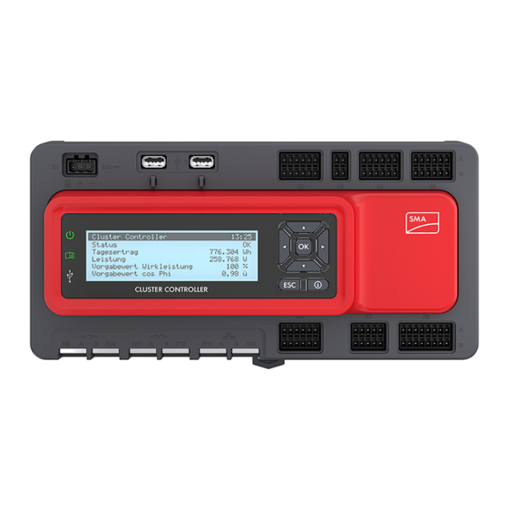
4 Product Description SMA Solar Technology AG Display view Explanation System overview Displays the system status, the current daily yield, the nominal sys- tem power and the current setpoints for active power and reactive power If no button on the keypad is pressed within five minutes, the Clus- ter Controller switches to the display view System overview. - Page 21 SMA Solar Technology AG 4 Product Description Designation Explanation [OK] Confirms the selected action Cancels the selected action [ESC] ⓘ Opens the display view System status Installation Manual ClusterController-IA-en-15...
-
Page 22: Mounting
5 Mounting SMA Solar Technology AG Mounting Requirements for Mounting Requirements for the mounting location: Product can cause radio interference in living areas The product is a device of ITE class A (EN 55022) and can cause radio interference in living areas. -
Page 23: Mounting The Cluster Controller
SMA Solar Technology AG 5 Mounting Figure 7: Minimum clearances Permitted and prohibited mounting positions: ☐ The Cluster Controller must be mounted so that the ventilation slots face upward and downward. This ensures optimum heat dissipation. Figure 8: Permitted and prohibited mounting positions Mounting the Cluster Controller... - Page 24 5 Mounting SMA Solar Technology AG ☐ In order to mount the Cluster Controller, the top-hat rail must be at least 26 cm long. When a top-hat rail power supply unit is used, the top-hat rail must be correspondingly longer. ☐ The top-hat rail must be securely mounted on the wall or in the switch cabinet.
-
Page 25: Connection And Commissioning
SMA Solar Technology AG 6 Connection and Commissioning Connection and Commissioning Overview of the Connection Area Figure 9: Overview of the connection area Position Quantity Designation Explanation Terminal for the voltage supply – Terminal for grounding USB port for exporting system data... -
Page 26: Functions Of The Terminals And Pin Groups
6 Connection and Commissioning SMA Solar Technology AG Position Quantity Designation Explanation X11, X12 Reserved for future applications X9, X10 Network ports for connecting the inverters (Speed- wire) Functions of the Terminals and Pin Groups The digital and analog terminals of the Cluster Controller are divided into pin groups. Each pin group forms one of the digital or analog inputs or outputs. - Page 27 SMA Solar Technology AG 6 Connection and Commissioning Terminal Pin group Function Digital input 5 A1 to A3 Signal 1 of 4 for the reactive power set- point in grid management services Digital input 6 A4 to A6 Signal 2 of 4 for the reactive power set- point in grid management services Digital input 7...
-
Page 28: Cable Requirements
6 Connection and Commissioning SMA Solar Technology AG Terminal Pin group Function X11, X12 – – Reserved for future applications X13, X14 – 1 to 8 Network ports for connection to LAN Cable Requirements UV resistance of connection cables Connection cables to be laid outdoors must be UV-resistant or routed in a UV-resistant cable channel. -
Page 29: Performing Pin Coding
SMA Solar Technology AG 6 Connection and Commissioning Terminal Cable requirements Temperature inputs (connec- ☐ Number of insulated conductors for tolerance ±2°C: at least tion cable) ☐ Number of insulated conductors for tolerance ±0.5°C: at least four ☐ Conductor cross-section: at least 4 x 0.25 mm²... -
Page 30: Preparing Connection Cables For Connection To Multipole Plugs
6 Connection and Commissioning SMA Solar Technology AG Procedure: 1. Insert one of the coding tabs on the coding element, parallel to the conductor axis, into the pin to be coded. 2. Remove the coding tab from the coding element by snapping it off. - Page 31 SMA Solar Technology AG 6 Connection and Commissioning • Press the shield clamp onto the cable shield. The cable shield must be clamped under the shield clamp as completely as possible. • Depending on the number of connection cables, split the wire required for shielding into pieces with a length 40 mm.
-
Page 32: Connecting The Cluster Controller To The Voltage Supply
6 Connection and Commissioning SMA Solar Technology AG Connecting the Cluster Controller to the Voltage Supply Danger to life due to electric shock from touching an ungrounded product Touching an ungrounded product can cause a lethal electric shock. • Ensure that the product is integrated in the existing overvoltage protection. - Page 33 SMA Solar Technology AG 6 Connection and Commissioning 3. Connect the grounding conductor to the grounding terminal. Observe the position of the terminal (see Section 6.1, page 25). Observe the order given below and hand-tighten the fastening screw (torque: 0.8 Nm): • Fastening screw •...
- Page 34 6 Connection and Commissioning SMA Solar Technology AG Figure 10: Pin assignment for terminal X1 Signal Explanation Not assigned Reserved for future applications 24 V Input voltage 24 V DC Ground Procedure: 1. Mount the power supply unit (see manual from manufacturer).
-
Page 35: Checking And Setting The Cluster Controller System Time
SMA Solar Technology AG 6 Connection and Commissioning • If the problem persists, contact the Service (see Section 11, page 83). Checking and Setting the Cluster Controller System Time Before connecting the Cluster Controller to the Speedwire network and before commissioning the inverters, you must check the Cluster Controller display to verify that the correct system time is displayed on the Cluster Controller. -
Page 36: Connecting The Cluster Controller To A Speedwire Network
6 Connection and Commissioning SMA Solar Technology AG 5. Log in either as User or as Installer with the corresponding default system password for the user group. This makes the language change take effect on the user interface and on the... - Page 37 SMA Solar Technology AG 6 Connection and Commissioning Observe the configuration of the router and the network switch For the Speedwire connection, the product uses IP addresses from the Unicast range and also IP addresses from the Multicast range 239/8 (239.0.0.0 to 239.255.255.255).
-
Page 38: Connecting The Cluster Controller To The Lan
1 GB per month. The data volume depends, among other things, on the number of inverters, the frequency of device updates, the frequency of data transfer to Sunny Portal and the use of FTP push. • SMA recommends using an Internet flat rate. ClusterController-IA-en-15 Installation Manual... -
Page 39: Connecting Usb Data Carriers To The Cluster Controller
☐ Up to two USB data carriers, e.g. two USB flash drives (see Section 10 "Accessories", page 82 If you use a USB data carrier other than that offered by SMA as an accessory, the USB data carrier must meet the requirements stated below. -
Page 40: Connecting Sensors To The Cluster Controller
6 Connection and Commissioning SMA Solar Technology AG Requirements for USB data carriers: ☐ Maximum storage capacity: 2 TB ☐ Supported file systems: FAT 16 or FAT 32 Use of USB hard disks with external power supply is recommended In the case of USB hard disks with power supply via the USB interface, malfunctions can occur if the connected USB hard disk temporarily has a greater electricity demand than that provided for by the USB 2.0 standard. - Page 41 SMA Solar Technology AG 6 Connection and Commissioning Connecting the Outside Temperature Sensor Additionally required material (not included in the scope of delivery): ☐ 1 outside temperature sensor ☐ 1 connection cable (see Section 6.3 "Cable Requirements", page 28) Requirements: ☐ The sensor must be technically suitable for connection to the temperature inputs (see Section 9, page 78).
- Page 42 6 Connection and Commissioning SMA Solar Technology AG 3. For connection to the Cluster Controller using four-conductor connection technology, perform the following steps: • On the five-pole plug, unlock conductor entry 1 using a screwdriver and insert the insulated conductor of the wire into the conductor entry.
-
Page 43: Connecting An Irradiation Sensor
SMA Solar Technology AG 6 Connection and Commissioning Procedure: 1. Connect the connection cable to the module temperature sensor (see the manual from manufacturer). Trim the unneeded insulated conductors up to the cable shield and note down the conductor colors. -
Page 44: Connecting Additional Sensors
6 Connection and Commissioning SMA Solar Technology AG Figure 15: Pin assignment for pin group Analog current input 1 Signal Explanation Not assigned Reserved for future applications Current input I− Current return Shield ground Procedure: 1. Connect the connection cable to the irradiation sensor (see the manual from manufacturer). - Page 45 SMA Solar Technology AG 6 Connection and Commissioning Display of measured values from pin group Analog voltage input 4 If no sensor is connected to the pin group Analog voltage input 4, a measured value for this pin group of up to 2.2 V will nevertheless be shown on the display and the user interface of the Cluster Controller.
- Page 46 6 Connection and Commissioning SMA Solar Technology AG Pin group Signal Explanation Analog current input 2 Not assigned Reserved for future applications Current input I− Current return Shield ground Analog current input 3 Not assigned Reserved for future applications Current input I−...
-
Page 47: Connections For Grid Management Services
SMA Solar Technology AG 6 Connection and Commissioning Requirements: ☐ The sensor must be technically suitable for connection to the analog inputs (see Section 9, page 78). ☐ The connection cable must be prepared for connection to the multipole plug (see Section 6.5, page 30). -
Page 48: Digital Setpoint Signal
6 Connection and Commissioning SMA Solar Technology AG In the event that the Cluster Controller evaluates a setpoint as invalid or does not receive a setpoint within a configurable interval, you can make additional settings for the fallback. Configure the grid management services via the Cluster Controller user interface (see the Cluster Controller user manual). -
Page 49: Connecting A Signal Source To A Digital Input For Active Power Limitation
SMA Solar Technology AG 6 Connection and Commissioning Connection of a signal source with potential-free relay contact Figure 18: Connection of a signal source with potential-free relay contact (example) Connection of a 24 V Signal Source with Digital Output Signals Figure 19: Connection of a 24 V signal source with digital output signals (example) 6.12.2.2 Connecting a Signal Source to a Digital Input for Active Power... - Page 50 6 Connection and Commissioning SMA Solar Technology AG Figure 20: Pin assignment for pin groups on terminal X4 Pin group Pin assignment Explanation Digital input 1 24 V Voltage supply output Signal 1 of 4 for active power Input limitation Reference potential Digital input 2...
-
Page 51: Connecting A Signal Source To A Digital Input For Reactive Power Setpoint
SMA Solar Technology AG 6 Connection and Commissioning Procedure: 1. Connect the connection cable to the digital signal source (see the manual from manufacturer). Trim the unneeded insulated conductors up to the cable shield and note down the conductor colors. - Page 52 6 Connection and Commissioning SMA Solar Technology AG Figure 21: Pin assignment for pin groups on terminal X5 Pin group Pin assignment Explanation Digital input 5 24 V Voltage supply output Signal 1 of 4 for reactive power Input setpoint Reference potential Digital input 6...
-
Page 53: Digital Signal Setpoint When Using Multiple Cluster Controllers
SMA Solar Technology AG 6 Connection and Commissioning Procedure: 1. Connect the connection cable to the digital signal source (see the manual from manufacturer). Trim the unneeded insulated conductors up to the cable shield and note down the conductor colors. -
Page 54: Analog Setpoint Signal
6 Connection and Commissioning SMA Solar Technology AG Figure 22: Transmission of digital signals for active power limitation to two Cluster Controllers via relays K1 and K2 of a ripple control receiver (example) 6.12.3 Analog Setpoint Signal 6.12.3.1 Connecting a Signal Source to an Analog Input for Active Power Limitation Analog signals for active power limitation are transmitted to the pin group Analog current input 2... -
Page 55: Connecting A Signal Source To An Analog Input For Reactive Power Setpoint
SMA Solar Technology AG 6 Connection and Commissioning Figure 23: Pin assignment for pin group Analog current input 2 Signal Explanation Not assigned Reserved for future applications Current input I− Current return Shield ground Procedure: 1. Connect the connection cable to the analog signal source (see the manual from manufacturer). -
Page 56: Analog Setpoint Signal When Using Multiple Cluster Controllers
6 Connection and Commissioning SMA Solar Technology AG Requirements: ☐ The signal source must be technically suitable for connection to the analog inputs (see Section 9, page 78). ☐ The connection cable must be prepared for connection to the multipole plug (see Section 6.5, page 30). -
Page 57: Setpoint Via Modbus Client
SMA Solar Technology AG 6 Connection and Commissioning Figure 25: Transmission of analog current signals for active power limitation to three Cluster Controllers via isolation amplifiers (example) 6.12.4 Setpoint via Modbus Client Requirements: ☐ The Cluster Controller and the Modbus client must be located in the same LAN. -
Page 58: Connecting A Remote Terminal For Feedback Via Digital Signal
6 Connection and Commissioning SMA Solar Technology AG 6.12.5.2 Connecting a Remote Terminal for Feedback via Digital Signal Using suitable remote terminals (e.g. optical or acoustic signal generators), the status of the system can be fed back to you via the pin groups Digital output 1, Digital output 2, and Digital output 3 of the X2 terminal. -
Page 59: Connecting A Remote Terminal For Feedback Via Analog Signal
SMA Solar Technology AG 6 Connection and Commissioning Pin group Relay Signal Explanation Digital output 3 Back contact Change-over con- tact Front contact Procedure: 1. Connect the connection cable to the remote terminal (see the manual from manufacturer). Trim the unneeded insulated conductors up to the cable shield and note down the conductor colors. - Page 60 6 Connection and Commissioning SMA Solar Technology AG Figure 27: Pin assignment for the pin groups Analog current output 1, Analog current output 2 and Analog current output 3 Pin group Signal Explanation Analog current output 1 Current output I− Current return Shield ground Analog current output 2...
- Page 61 SMA Solar Technology AG 6 Connection and Commissioning Figure 28: Interpretation of the signal strength as a percentage value of the active power limitation in relation to the inverter parameter Currently set active power limit or Pmax Example: Interpretation of signal strength as a reactive power setpoint value Depending on the value of the reactive power setpoint that was selected via the user interface (see the Cluster Controller user manual), the strength of the feedback signal corresponds either to the...
- Page 62 6 Connection and Commissioning SMA Solar Technology AG Figure 30: Interpretation of the signal strength as displacement power factor cos φ Procedure: 1. Connect the connection cable to the remote terminal (see the manual from manufacturer). Trim the unneeded insulated conductors up to the cable shield and note down the conductor colors.
-
Page 63: Feedback When Using Multiple Cluster Controllers
SMA Solar Technology AG 6 Connection and Commissioning • Depending on the remote terminal and the pin assignment for the pin group Analog current output 3, identify the conductor entries that are required for connecting the connection cable. • Release the required conductor entries using a screwdriver and insert the insulated conductors into the conductor entries. -
Page 64: Checking The Connections Via The Display
6 Connection and Commissioning SMA Solar Technology AG Feedback via analog signal When using multiple Cluster Controllers, you must connect one remote terminal to the analog current outputs of each Cluster Controller (see Section 6.12.5.3, page 59). 6.13 Checking the Connections via the Display You can use the Cluster Controller display to check whether the connections have been made... -
Page 65: Configuring A Static Lan
SMA Solar Technology AG 6 Connection and Commissioning 6.14 Configuring a Static LAN You can configure the Cluster Controller and the inverters in the system for a static LAN (see the Cluster Controller user manual). The Cluster Controller and the inverters are configured for automatic address allocation via DHCP by default. -
Page 66: Troubleshooting
7 Troubleshooting SMA Solar Technology AG Troubleshooting LED States 7.1.1 Operation LEDs Configuration of the Status LED ( The status LED can display the following statuses: • Status of the Cluster Controller • Status of the connected inverters • Status of the system communication •... - Page 67 SMA Solar Technology AG 7 Troubleshooting Status Cause and corrective measure glowing green Normal operation Status ( glowing yellow At least one device has the status Warning. Corrective measures: • Check the Cluster Controller event log (see the Cluster Controller user manual).
- Page 68 7 Troubleshooting SMA Solar Technology AG Status Cause and corrective measure Data carrier status The Cluster Controller is starting and no information is yet available for data export or for the USB data car- rier. Corrective measures: • Wait until the Cluster Controller has completed the start process and is ready for operation.
-
Page 69: Network Port Leds
SMA Solar Technology AG 7 Troubleshooting 7.1.2 Network Port LEDs Status Cause and corrective measure Link/Activity No network connection established. (green) The Cluster Controller is not connected to the voltage sup- ply. Corrective measures: • Connect the Cluster Controller to the voltage supply (see Section 6.6, page 32). -
Page 70: Errors In The Cluster Controller Or The Connected Devices
7 Troubleshooting SMA Solar Technology AG Errors in the Cluster Controller or the Connected Devices General information Problem Cause and corrective measure The Cluster Controller does not start. The Cluster Controller is not connected to the voltage sup- The LEDs and the display are off. - Page 71 SMA Solar Technology AG 7 Troubleshooting Problem Cause and corrective measure The correct number of connected in- Communication with at least one inverter is disturbed. verters is not shown on the display. Either the Cluster Controller has not yet registered with one or more inverters or the connection to one or more in- verters has been interrupted.
- Page 72 7 Troubleshooting SMA Solar Technology AG Problem Cause and corrective measure No measured values for the con- If no measured values are displayed for the irradiation nected irradiation sensor are shown sensor, either the characteristic curve of the irradiation sen- on the display.
- Page 73 SMA Solar Technology AG 7 Troubleshooting Problem Cause and corrective measure The login page does not open. The Cluster Controller is not connected to the voltage sup- ply. Corrective measures: • Ensure that the three-pole plug for the voltage supply is connected to terminal X1 of the Cluster Controller.
-
Page 74: Resetting The Cluster Controller
7 Troubleshooting SMA Solar Technology AG Problem Cause and corrective measure The login page does not open. There is a problem in the LAN. Corrective measures: • Ensure that the network cables are correctly connected to the Cluster Controller (see Section 6.9, page 38). - Page 75 SMA Solar Technology AG 7 Troubleshooting 3. To exit the display view, press [ESC]. 4. To confirm the settings that are to be reset, perform the following steps: • Press [OK]. ☑ The display view Confirm the resetting appears. • Select OK and confirm with [OK].
-
Page 76: Decommissioning
8 Decommissioning SMA Solar Technology AG Decommissioning Disassembling the Cluster Controller Danger to life due to electric shock Lethal voltages are present at the connection point of the utility grid. • Disconnect the connection point from the utility grid using the separator (e.g. circuit breaker). -
Page 77: Disposing Of The Product
SMA Solar Technology AG 8 Decommissioning Disposing of the Product • Dispose of the product in accordance with the locally applicable disposal regulations for electronic waste. Installation Manual ClusterController-IA-en-15... -
Page 78: Technical Data
9 Technical Data SMA Solar Technology AG Technical Data General Data Status display LEDs, display Operation Keypad, integrated web server Mounting type Top-hat rail mounting Mounting location Indoors Mechanical Data Width x height x depth 275 mm x 133 mm x 71 mm Weight 1.2 kg... - Page 79 Maximum Cable Length for Communication Speedwire* 100 m Ethernet* 100 m * between two nodes when using installation cables Maximum Number of Devices SMA devices with Speedwire interface For model "CLCON-S-10": 25 For model "CLCON-10": 75 Network Ports Quantity (Speedwire) Quantity (LAN) Auto-MDIX (auto-crossing)
- Page 80 9 Technical Data SMA Solar Technology AG Digital outputs Quantity Design Potential-free relay contacts Maximum switching power 30 W Maximum voltage load 48 V Maximum cable length 30 m Analog inputs Number of analog inputs for current signals Number of analog inputs for voltage signals Internal resistance 450 Ω...
- Page 81 SMA Solar Technology AG 9 Technical Data Specification USB 2.0 Hi‑Speed Maximum current 500 mA Maximum cable length Installation Manual ClusterController-IA-en-15...
-
Page 82: Accessories
USB flash drive with storage capacity of USB-FLASHDRV8GB 8 GB * Not available in all countries. For information on whether an accessory is available in your country, visit the website of your country's SMA subsidiary at www.SMA-Solar.com or contact your distributor. ClusterController-IA-en-15 Installation Manual... -
Page 83: Contact
SMA Solar Technology AG 11 Contact 11 Contact If you have technical problems with our products, please contact the SMA Service Line. We need the following information in order to provide you with the necessary assistance: • Cluster Controller: – Serial number – Firmware version •... - Page 84 Abu Dhabi Mumbai +971 2 234-6177 +91 22 61713888 SMA Solar (Thailand) Co., Ltd. SMA Technology Korea Co., Ltd. +66 2 670 6999 +82-2-520-2666 South Africa SMA Solar Technology South Argentina SMA South America SPA Africa Pty Ltd. Brasil Santiago Cape Town Chile +562 2820 2101 08600SUNNY (78669) Perú...
- Page 86 SMA Solar Technology www.SMA-Solar.com...
Need help?
Do you have a question about the CLCON-10 and is the answer not in the manual?
Questions and answers