Table of Contents
Advertisement
Available languages
Available languages
Quick Links
Download this manual
See also:
Instruction Manual
Advertisement
Table of Contents

Related Manuals for Bticino 391716


Summary of Contents for Bticino 391716
- Page 1 391715 391716 Manuale di istruzioni User manual 391717...
-
Page 2: Bilanciamento Del Bianco
391715 - 391716 - 391717 CARATTERISTICHE • Telecamera con potente zoom e opzioni di configurazione 391715 391716 391716 Zoom ottico Zoom digitale Ingrandimento zoom max x100 x324 x444 Elevata compensazione del controlu- Funzione Privacy Mask (Zona Privata) Funzione Day & Night Modalità... - Page 3 Prima di procedere all’installazione, leggere attentamente le istruzioni associate e individuare un luogo di montaggio idoneo in funzione del prodotto. Non aprire, smontare, alterare o modificare l’apparecchio eccetto speciale menzione indicata nel manuale. Tutti i prodotti Bticino devono essere esclusivamente aperti e riparati da personale adegua- tamente formato e autorizzato da Bticino.
-
Page 4: Contenuto Della Confezione
391715 - 391716 - 391717 CONTENUTO DELLA CONFEZIONE • Prodotto e accessori Accessori standard Corpo principale e staffa di montaggio superficiale [cavo principale, chiave a brugola] Accessori per modelli con funzione Alarm In/Out Staffa di montaggio a parete [Cavo I/O] [viti: metriche M5x15, tirafondi testa esagonale N°14x50]... -
Page 5: Dip Switch
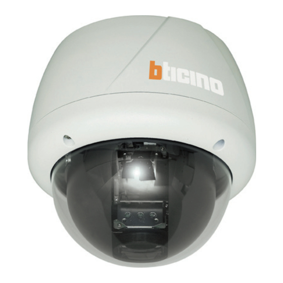
Descrizione della parte principale (modello 391715) Foro vite di montaggio Gancio di montaggio DIP Switch Connettore principale Porta I/O sensore Copertura cupola • Copertura cupola Non staccare la protezione di vinile dalla copertura della cupola prima di aver completato le operazioni di installazione, in modo da proteggere la copertura da graffi o polvere. - Page 6 391715 - 391716 - 391717 CONFIGURAZIONE DIP SWITCH Prima di installare la telecamera, regolare il DIP switch per impostare l’ID della telecamera e il protocollo di comunicazione. • Prodotto e accessori • Configurazione ID telecamer • I numeri ID delle telecamere sono configurati con numeri binari. Vedi gli esempi indicati qui sotto.
- Page 7 • Configurazione del protocollo di comunica • Scegliere un protocollo adatto alla combinazione del DIP switch. Modalità DIP Switch Protocollo (Pin 1) (Pin 2) (Pin 3) PELCO-D, 2400 bps PELCO-D, 9600 bps PELCO-P, 4800 bps PELCO-P, 9600 bps Altri Dedicato • Far corrispondere il protocollo della telecamera con il protocollo della telecamera nell’impostazione del DVR o del controller per il controllo della telecamera.
-
Page 8: Avvertenza Importante
391715 - 391716 - 391717 INSTALLAZIONE CON STAFFA DI MONTAGGIO A PARETE a Fare un foro di diametro 30~40mm sulla superficie di b Tirare il/i filo/i e il/i cavo/i per il sistema come mo- montaggio per far passare il/i filo/i e il/i cavo/i attra- strato qui sotto. - Page 9 INSTALLAZIONE CON STAFFA PER MONTAGGIO A SOFFITTO COD. 391848 a Togliere il pannello del soffitto e tagliare un foro del b Tirare il/i filo/i e il/i cavo/i per il sistema, come illu- diametro di 30~40mm nel pannello per far passare strato qui sotto.
- Page 10 391715 - 391716 - 391717 COLLEGAMENTI E CABLAGGIO ALIMENTAZIONE CAVO PRINCIPALE MONITOR CAVO AUDIO MIC. SPEAKER RS-485 CONTROLLER / DVR CAVO I/O I/O SENSORE SENSORE INTERRUTTORE PORTA • Descrizione porte • Cavo principale N° pin porta (RJ45) Colore cavo/connettor Segnale...
- Page 11 • Descrizione dell’alimentazione elettrica • Controllare attentamente la capacità di corrente e tensione della potenza nominale. La potenza nominale è indicata sul retro dell’unità principale. Intervallo tensione in ingresso Consumo corrente 11V ~ 15V DC 2,5 A • Per i modelli con ingresso DC, fare attenzione alla polarità dell’alimentazione DC, perché un ingresso DC sbagliato danneggerebbe permanentemente il sistema.
- Page 12 391715 - 391716 - 391717 • Ingressi allarme Interno Sensore 1 Sensore 3 • Prima di collegare i sensori, controllare le tensioni di comando e i tipi di segnale di uscita dei sensori. Dato che i tipi di segnale di uscita dei sensori si dividono in generale in Collettore Aperto e Uscita di Tensione, il cablaggio deve essere fatto in modo corretto dopo aver preso in considerazione queste tipologie.
-
Page 13: Controlli Prima Della Messa In Funzione
CONTROLLI PRIMA DELLA MESSA IN FUNZIONE • Prima di accendere il sistema, controllare che il/i filo/i e il/i cavo/i siano collegati correttamente. • Controllare che l’ID telecamera sul controller sia selezionato correttamente. L’ID telecamera deve essere identico a quello della telecamera bersaglio. L’ID telecamera si può controllare leggendo il DIP switch della telecamera oppure sull’OSD • Se il controller supporta protocolli multipli, il protocollo deve essere modificato per corrispondere a quello della telecamera. -
Page 14: Specifiche Tecniche
391715 - 391716 - 391717 SPECIFICHE TECNICHE TELECAMERA (391715) Formato segnale video Sensore immagine CCD Interline Transfer da 1/4'' Pixel totali 795(O)x596(V) 470K Pixel effettivi 752(O)x582(V) 440K Risoluzione orizzontale 500 linee TV (Colore), 570 linee TV (B/N) Rapporto segnale rumore... - Page 15 TELECAMERA PART 391716 391717 Formato segnale video Sensore immagine CCD Interline Transfer da 1/4'' Pixel totali 795(O)x596(V) 470K Pixel effettivi 752(O)x582(V) 440K Risoluzione orizzontale 550 linee TV (Colore), 680 linee TV (B/N) Rapporto segnale rumore 50 dB (AGC OFF) Zoom ottico...
-
Page 16: Montaggio A Soffitto
391715 - 391716 - 391717 MECCANICA Modello 391715 Modelli 391716/391717 Montaggio a Montaggio a Montaggio a Montaggio a parete soffitto parete soffitto Cupola Policarbonato Materiale Interno Policarbonato, ABS Esterno Alluminio Dimensioni cupola Ø 107,5 mm/ Ø 4,2” Ø 150 mm/ Ø 5,9”... - Page 17 DIMENSIONI (MODELLO 691715) • Corpo principale • Tipo montaggio a soffitto • Tipo montaggio a parete...
- Page 18 391715 - 391716 - 391717 DIMENSIONI (391716/391717) • Corpo principale • Tipo montaggio a soffitto • Tipo montaggio a parete...
- Page 19 Pattern and/or Swings sequently and runs Presets, Pattern and/or Swings repetitively. A Group can be combined upto 20 functions with any of Preset/Pattern/Swing. • Privacy Masks are programmable, not to intrude on any other’s privacy : 391715 : MAX. 4 privacy zones 391716/391717 : 8 privacy zones...
- Page 20 Before carrying out the installation, read the instructions and take account of the product’s specific mounting location. Do not open up, dismantle, alter or modify the device except where specifically required to do so by the instructions. All Bticino products must be opened and repaired exclusively by personnel trained and approved by Bticino.
-
Page 21: Package Component
PACKAGE COMPONENT • Product & Accessories Main Body & Surface Mount Bracket Default Accessories [Main Cable, Wrench] Accessories for The Models with Alarm In/Out Function Wall Mount Bracket [I/O Cable] [Screws : Machine M5x15, Hex Lag #14x50] • Optional Brackets Ceiling Mount Bracket 391848 Corner bracket 391849 Pole bracket 391850... - Page 22 391715 - 391716 - 391717 MAIN PART DESCRIPTION Mounting Screw Hole Mounting Hook DIP Switch Main C onnector Sensor I/O Port Dome Cover • Dome Cover Do not detach the protection vinyl from the dome cover before finishing all the installation process to protect the dome cover from scratches or dust.
-
Page 23: Dip Switch Setup
DIP SWITCH SETUP Before installing the camera, set up the DIP switch to configure the camera ID and the communication protocol. • Camera ID Setup • DID numbers of cameras are set up with binary numbers. See the examples shown below. Binary Value ex: ID = 5 ex: ID = 10... -
Page 24: Switch Mode
391715 - 391716 - 391717 • Communication Protocol Setup • Select an appropriate Protocol with the DIP switch combination. Switch Mode Protocol (Pin 1) (Pin 2) (Pin 3) PELCO-D, 2400 bps PELCO-D, 9600 bps PELCO-P, 4800 bps PELCO-P, 9600 bps... -
Page 25: Installation With Wall Mount Bracket
INSTALLATION WITH WALL MOUNT BRACKET a Make a hole whose diameter is 30~40mm on the b Pull the wire(s) and cable(s) for the system as below. mounting surface to pass the wire(s) and cable(s) Wire the cable(s) to the ports. Insert the mounting through the mounting surface. -
Page 26: Installation With Ceiling Mount Bracket
391715 - 391716 - 391717 INSTALLATION WITH CEILING MOUNT BRACKET (391848) a Remove the ceiling tile from the ceiling and cut a b Pull the wire(s) and cable(s) for the system as below. hole whose diameter is 30~40mm on the ceiling Wire the cable(s) to the ports. -
Page 27: Wiring And Cabling
WIRING AND CABLING POWE R B NC MA IN CAB L E MONITOR A UDIO SPE A K E R CA B L E R S-485 CONT R OL L ER / DV R I/O CA B L E SE NSOR I/O DOOR SE NSOR SWITCH... -
Page 28: Current Consumption
391715 - 391716 - 391717 • Power Description • Carefully check the voltage and current capacity of the rated power. The rated power is indicated in the back of main unit. Input Voltage Range Current Consumption DC 11V ~ 15V 2,5 A • For the DC input models, be careful with the polarity of DC power. - Page 29 • Alarm Input • Before connecting sensors, check driving voltages and output signal types of the sensors. Since output signal types of the sensors are divided into Open Collector type and Voltage Output type in general, the wiring must be done properly after considering those types.
-
Page 30: Check Points Before Operation
391715 - 391716 - 391717 CHECK POINTS BEFORE OPERATION • Before turning on the system, check if the wire(s) and cable(s) are connected properly. • Check if the camera ID on the controller is properly selected. The camera ID must be identical to that of the target camera. -
Page 31: Specifications
SPECIFICATIONS CAMERA PART (391715) Video Signal Format Image Sensor 1/4'' Interline Transfer CCD Total Pixels 795(H)x596(V) 470K Effective Pixels 752(H)x582(V) 440K Horizontal Resolution 500 TV Lines(Color), 570 TV Lines(B/W) Video Signal-to-Noise 50 dB (AGC Off ) Zoom x10 Optical Zoom, x10 Digital Zoom Forcal Length F1.8, f=3.8~38mm Angle of View... - Page 32 391715 - 391716 - 391717 CAMERA PART 391716 391717 Video Signal Format Image Sensor 1/4'' Interline Transfer CCD Total Pixels 795(H)x596(V) 470K Effective Pixels 752(H)x582(V) 440K Horizontal Resolution 550 TV Lines(Color), 680 TV Lines(B/W) Video Signal-to-Noise 50 dB (AGC Off )
- Page 33 MECHANICAL 391715 Model 391716/391717 Models Ceiling Mount Wall Mount Ceiling Mount Wall Mount Dome Polycarbonate Material Internal Polycarbonate, ABS External Aluminium Dome Size Ø 107,5 mm/ Ø 4,2” Ø 150 mm/ Ø 5,9” Dimension 158,2 x 216 mm 274,5 x 227,3 mm Ø...
- Page 34 391715 - 391716 - 391717 DIMENSION (691715 Model) • Main Body • Ceiling Mount Type • Wall Mount Type...
- Page 35 DIMENSION (691716/ 391717 Models) • Main Body • Ceilign Mount Type • Wall Mount Type...
Need help?
Do you have a question about the 391716 and is the answer not in the manual?
Questions and answers