
Related Manuals for Sencore SLM 1479


Summary of Contents for Sencore SLM 1479
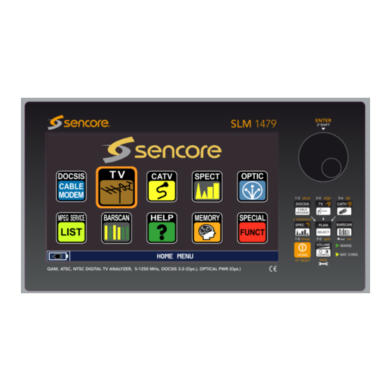
- Page 1 SLM 1479 CATV, TV, Signal Level Meter User Manual July 2017 Form 8150A www.sencore.com | 1.605.978.4600 Revision 1.1...
- Page 2 This document may also have links to third-party web pages that are beyond the control of Sencore. The presence of such links does not imply that Sencore endorses or recommends the content on those pages. Sencore acknowledges the use of third-party open source software and licenses in some Sencore products.
-
Page 3: Revision History
SLM 1479 User Manual Revision History Date Version Description Author 05/26/2016 Operations Manual for SLM 1479 07/13/2017 Small edits Page 3 (124) -
Page 4: Table Of Contents
SLM 1479 User Manual Table of Contents INTRODUCTION ..........................7 ................... 7 ACKAGE ONTENTS CD D .................... 8 ONTENTS SMART S .................... 8 OFTWARE ..................8 YSTEM NFORMATION SECTION 1: UNIT FAMILIARIZATION ..................9 1.1 F ............9 RONT ANEL... - Page 5 SLM 1479 User Manual 5.1 TV P ................... 36 ELECTION 5.2 TV D & A ............37 IGITAL NALOG EASUREMENTS 5.21 Main Digital TV Measurement Page ................37 5.22 Analog TV Measurements .................... 38 5.23 FM Radio Tuning & Measurement ................39 5.3 TV MPEG SERVICE L...
- Page 6 ......110 APTURING CREEN HOTS TO A EMORY TICK SLM 1479 SPECIFICATIONS ..................... 111 APPENDIX A – NORTH AMERICA CHANNEL PLANS ............114 APPENDIX B – CLEANING/MAINTENANCE INFORMATION ..........122 APPENDIX C - WARRANTY/SERVICE INFORMATION ............123 Page 6 (124)
-
Page 7: Introduction
USB cable, antenna, and SMART software. Package Contents Great care is taken to ensure the SLM 1479 shipped from the Sencore factory is free of defects, contains the supplied accessories and is securely packaged. Please inspect the package and contents upon receipt. If there has been significant damage please contact Sencore for further instructions. -
Page 8: Cd Disc Contents
SMART Software Users Guide which provides instructions on how to install, license, connect and use the SMART software. The CD further contains a driver file used for the USB connection from the PC to the SLM 1479 when establishing a connection for the SMART software. -
Page 9: Section 1: Unit Familiarization
SLM 1479 User Manual Section 1: Unit Familiarization 1.1 Front Panel Control Familiarization ENTER Ref. Main Function Description Second Function Power Home Press 2-3 sec to power on or off, Press/hold 10 seconds or more Pushbutton press briefly to return Home menu... -
Page 10: Right Side Panel Familiarization
SLM 1479 User Manual 1.2 Right Side Panel Familiarization The right side panel of the SLM 1479 contains several interface connection jacks along with an air intake fan and internal speaker. The following section provides a brief description. Ref. Main Function... -
Page 11: Top Panel Familiarization
Provides DOCSIS measurements and generation 1.4 Home Menu Icon Familiarization The Home Menu of the SLM 1479 is the first menu you see when powering on the meter. You may return to this menu from any other menu by briefly pressing the HOME pushbutton. -
Page 12: Powering On/Off
Includes program name, V-PID, A-PID, Encrypted Yes/No 1.5 Powering ON/OFF The SLM 1479 is powered on and off with the orange front panel pushbutton labeled “HOME” located at the bottom right of the instrument front panel. The HOME pushbutton has a circle with a line in it on the pushbutton. -
Page 13: Power Adapter
1.6 Power Adapter The SLM 1479 is supplied with a DC power supply that is used to power the instrument and to indirectly charge its internal battery. The power supply/adapter is a regulated 12 VDC with a positive center terminal on the connector to the instrument. The power supply is rated for ACV inputs ranging from 100-240 VAC @ 50/60 Hz and can deliver up to 3.0 amp of DC output current. - Page 14 Expect approximately 4 – 5 hours depending on power management settings and LNB powering. To extend the useable battery measurement time on a single charge, the SLM 1479 offers three power management features including: 1) Unit Auto Off, 2) Display Light Timer and, 3) Backlight Brightness. Please see the METER CONFIGURATION Menu (Section 3) of this manual for details on these settings.
-
Page 15: Battery Replacement
You need to be absolutely sure you have the proper replacement Li Po battery pack for your SLM 1479. Sensing wires to the battery pack are critical in battery charging/discharging and safety. ONLY an exact replacement or a suitable replacement battery provided from Sencore should be used. -
Page 16: Section 2: Quick Start Guide
Section 2: Quick Start Guide 2.1 Navigation The SLM 1479 features a touch sensitive screen but supplements operation with a mechanical control knob and mechanical front panel switches. In combination, they are used to navigate, make selections, and initiate tests. The ability to make selections directly from the screen with a finger touch greatly simplifies meter use. -
Page 17: Navigation - Exercise
SLM 1479 User Manual 2.2. Navigation – Exercise To become familiar S E N C O R E S L M 1 4 79 ENTER with the SLM 1479’s MEMORY navigation follow the CABLE PLAN steps below: (#s POLAND MASTER reference fingers in RUSS. -
Page 18: Dropdown Menu Selections
SLM 1479 User Manual 2.3 Dropdown Menu Selections Several fields within the SLM 1479 screen have dropdown menus in which selections or entries are made. This section briefly explains how to select or enter values within a drop down menu. -
Page 19: Measurement Signal Selection
CATV measurement which may be selected via the touch panel DOCSIS icon or by pressing the DOCSIS pushbutton. The SLM 1479 always retains the last selected signal type as its selected operational base until you return to the HOME Menu and select a different type or press the TV or CATV pushbutton to change signal types. -
Page 20: Quick Start Measurements
TV or cable measurements. It is not intended to completely summarize all the information contained in this manual. Please reference other portions of the manual as needed to answer questions and become familiar with the SLM 1479 and its features. -
Page 21: Entering Field Values
SLM 1479 User Manual 2.7 Entering Field Values Some field values in the SLM 1479 are entered with a popup entry menu. This menu presents several entry boxes in the center of the display screen area. The number of fields represent the number of digits available for entry. - Page 22 SLM 1479 User Manual Main Measurement Page to MPEG Service List Page When in the main measurement page touching the right area of the screen below the video screen section advances the measurement to the MPEG SERVICE LIST function or display screen. Touching the same area of the MPEG SERVICE LIST screen returns the measurement to the main measurement page.
-
Page 23: Section 3: Meter Configuration
SLM 1479 User Manual Section 3: Meter Configuration The DSA 1491 has two meter configuration menus. They include an initial CONFIG Pushbutton or “Quick View” menu and an extended CONFIGURATION MENU. The Quick View menu is accessed by briefly touching the CONFIG pushbutton at the bottom right corner of the meter. -
Page 24: Brightness
The image format may be set to either16:9 or 4:3. The selection changes the aspect ratio of the video viewed on the SLM 1479’s display. To select the image format, touch the IMAGE FORMAT field, and touch the highlighted section to increment to the desired aspect ratio. -
Page 25: Battery Saving
RF OUT connector near the OPTICAL IN connector on the top of the meter to the RF-IN jack at the top center of the meter. The SLM 1479 does not contain an internal connection path from the optical converter to the meter’s RF analyzing circuitry. -
Page 26: Configuration Menu
SLM 1479 User Manual 3.2 Configuration Menu The CONFIGURATION MENU provides setup options for the meter and measurement functions. The CONFIGURATION MENU is accessed by first pressing the VOL/CONFIG pushbutton at the bottom right of the meter’s front panel. Secondly, touch the CONFIGURATION MENU listing near the bottom of the Quick View Config. - Page 27 3.21.5 GRAPHICS COLOR The GRAPHICS COLOR field provides selections for the color scheme used by the various displays and menus of the SLM 1479. The color schemes include BLUE, GREEN, GREY, and BROWN to match personal preferences. The color scheme selected does not influence the battery use time.
- Page 28 3.21.7 BATTERY TEST The BATTERY TEST field provides an automated battery test and reconditioning routine performed by the SLM 1479. The feature performs an internal battery test. The BATTERYTEST checks/recovers the battery capacity and recalculates the meter’s battery charge indicator to get precise Indications on the charge battery status. For example, if the battery test indicates “000255000,”...
-
Page 29: Tv Configuration Menu
3.21.11 LAN CONFIGURATION The LAN CONFIGURATION field provides selections to configure the RJ45 or LAN connection port of the SLM 1479 for connection to a network. The menu provides selection for a DHCP (Dynamic Host Connection Protocol) IP connection/configuration or static connection/configuration. The static configuration provides entry of IP, Network Mask and Gateway address entries. - Page 30 3.22.4 FIELD STRENGTH & EDIT ANT. FACTOR The FIELD STRENGTH field provides modifications to the TV level measurements when using the SLM 1479 to measure TV coverage field strengths. The field provides several selections of common antenna types. Or, you may use an alternate antenna and select the CUSTOM antenna selection.
-
Page 31: Cable Modem
SLM 1479 User Manual normal TV antenna dBmV measurements, the FIELD STRENGTH field should remain “OFF.” 3.23 CABLE MODEM The CABLE MODEM listing provides selection of the settings used for the meter’s cable modem and DOCSIS testing of a cable system. The settings... -
Page 32: Catv Configuration
3.24 CATV CONFIGURATION The CATV listing provides settings relative to using the CATV measurements provided by the SLM 1479. To access the CATV field navigate to the CONFIGURATION MENU screen and touch the CATV listing. The CATV menu appears to the right and SNR LINE, and DISCOVERY. -
Page 33: Meter Info Menu
MONITOR, and HD REMOTE CONTROL are not currently available. Some options on the list are provided courtesy of Sencore and are not additional purchased options. Examples include the TV MINISPECTRUM, VIDEO WAVE F. MONITOR, and HD AUDIO DOLBY +. These options are included with every SLM 1479. -
Page 34: Diagnostic Test
SLM 1479 User Manual 3.26 DIAGNOSTIC TEST The DIAGNOSTIC listing in the CONFIGURATION MENU provides a self-test of the meters internal circuits. The circuits should all indicate “OK” if they are working and responding to the microcontroller. If a listing does not indicate OK, a likely problem exists. -
Page 35: Section 4 Video In Monitoring
SLM 1479 User Manual Section 4 Video In Monitoring The SLM 1479 offers a video input monitoring capability to supplement its TV-RF analyzing capabilities. This section summarizes the video input features and provides operational information. 4.1 Video In The video display of the SLM 1479 may be used as an NTSC composite video monitor through the use of the VIDEO IN jack located at the top left of the meter. -
Page 36: Section 5: Tv Broadcast Measurements
Manual channel plans may be created in the SMART software. The MANUMEMORY of the SLM 1479 includes a USATSC plan with all the off-air TV channels from 2 to 69. This plan may be edited in the MEMORY MENU to customize it for your local channels. -
Page 37: Tv Digital & Analog Measurements
TV pushbutton or the MEAS icon at the right. The meter advances to the TV MEASUREMENT page. 5.2 TV Digital & Analog Measurements The SLM 1479 provides a comprehensive analysis of a TV broadcast signal, either digital or analog. Digital signal analysis includes standard 8VSB analysis. -
Page 38: Analog Tv Measurements
SLM 1479 User Manual 4. DC@RF: This field indicates OFF as the SLM 1479 does not provide switchable output DC voltage 5. FREQ: The center frequency of the digital channel or video carrier of analog channel. Selectable field permits frequency tuning. -
Page 39: Fm Radio Tuning & Measurement
SLM 1479 User Manual voltmeter measurement. The 2 page provides a waveform monitor screen in which the signal-to-noise ratio and hum is measured on a selected video line. The 3 measurement page provides a waveform monitor (WFM) screen in which the selected scan line of detected video is scanned and displayed. -
Page 40: Tv Mpeg Service List
SLM 1479 User Manual 5.3 TV MPEG SERVICE List The MPEG SERVICE LIST measurement page of the SLM 1479 provides information regarding the MPEG stream and video service/programs of the selected TV channel. The MPEG SERVICE LIST page may be accessed in two ways. From the HOME Menu with the TV icon highlighted, touch the MPEG SERVICE LIST icon. -
Page 41: Tv Constellation & Monitoring
SLM 1479 User Manual 5.32 TV Constellation & Monitoring The constellation measurement page provides a second page of analysis of a broadcast digital channel. The top and bottom fields of the page are the same as the main measurement page. The left center of the Constellation & Info page provides a constellation analysis. -
Page 42: Tv Mpeg Video Service Monitoring
SLM 1479 User Manual 5.33 TV MPEG Video Service Monitoring The video displayed in the Main Measurement Page or in the MPEG SERVICE LIST page may be expanded to fill the display screen. For a full screen view of the demodulated video of a selected video service touch the displayed video section of the screen. -
Page 43: Tv Measurement Popup Menu
5.43 VISUAL NIT The SLM 1479 provides an information page of the data found in a DVB compliant signal’s NIT (Network Information Table). This feature is not applicable when analyzing North American ATSC broadcast signals as they do not include a NIT table. -
Page 44: Channel Logger
SLM 1479 User Manual 5.44 CHANNEL LOGGER The SLM 1479 includes the ability to continuously monitor and chart the critical RF analyzing measurements of a broadcast channel over a selected time period. The charting allows you to see events or times of RF signal impairments or reception interruptions. - Page 45 SLM 1479 User Manual meter USB-A port. Setup meter to the desired channel to be monitored/logged. Press the MENU & ? menu and select Channel Logger feature. Press the MENU field in the SINGLE CHANNNEL MONITORING screen. In the menu,...
-
Page 46: Tv Spectrum Analyzer
SLM 1479 User Manual 5.5 TV Spectrum Analyzer The TV spectrum analyzer provides detailed spectral analysis of both analog and digital analog TV signals. To select the spectrum analyzer function from the HOME menu with the TV icon highlighted, touch the SPEC icon. You may also access the spectrum analyzer from any of the other measurement pages by pushing the SPEC pushbutton at the right of the display. -
Page 47: Tv Spectrum Analyzer Popup Menu
SLM 1479 User Manual 5.6 TV Spectrum Analyzer Popup Menu The TV Spectrum Analyzer includes a popup menu that provides settings for the spectrum analyzer and provides handy features. It further provides a convenient access to the HELP function. Touch the MENU &... -
Page 48: Spectrum Analyzer Marker Bandwidth Measurement
SLM 1479 User Manual 5.62 Spectrum Analyzer Marker Bandwidth Measurement The Spectrum Analyzer includes a marker bandwidth (MRK.BW.) measurement. This measurement provides a means to select a bandwidth of interest for a level measurement. The bandwidth is adjustable from 0 to 8 MHz. When... -
Page 49: Tv Special Functions
SLM 1479 User Manual 5.7 TV Special Functions The TV Special Functions menu provides several SPECIAL FUNCTIONS listings. The TV special functions menu is selected BUZZ & NOIS. MARG. GR. by pressing the SPECIAL FUNCT icon on the HOME Menu when the TV icon is highlighted. This... - Page 50 SLM 1479 User Manual Measurements in the BUZZ&NOISE MAR.GR function include the following: NOISE MARG : The Current Noise Margin measurement Maximum or best Noise Margin measurement since the test began – MAX N. MARG: signal lock Minimum or worst noise margin measurement since test began – signal MIN N.
-
Page 51: Tv Attenuation Test
SLM 1479 User Manual 5.72 TV ATTENUATION TEST The TV ATTENUATION TEST is a special test that simultaneously measures the signal power of three TV frequencies and meters the attenuation of the signals compared to a reference or “calibrated” level. The test may be used to determine attenuation or loses between two signal points. -
Page 52: Tv Memory Management
SLM 1479 User Manual 5.8 TV Memory Management The MEMORY MENU provides channel plan MEMORY creating, test logging features and channel plan management functions. The MEMORY MENU is accessed by pressing the MEMORY icon with the head/brain picture on it. On the Home Menu or in the TV BROADCAST PLAN SELECTION Menu touch the MEMORY icon. -
Page 53: Automemorytv - Scan To Create A Channel Plan
SLM 1479 User Manual 5.81 AUTOMEMORYtv – Scan to Create a Channel Plan MEMORY MENU The AUTOMEMORYtv feature FROM PLAN: USABRO AUTOMEMORY tv found in the MEMORY MENU TO FILE N : AUTO 3 provides the ability to SAVE DATALOGGER LEVEL: >... -
Page 54: Save Datalogger - Tv Auto Measure & Store
SLM 1479 User Manual 1. Navigate to the MEMORY MENU and touch the AUTOMEMORYtv field. 2. Set the FROM PLAN field to USABRO. This is set by selecting the TV measure function. Then press the PLAN pushbutton and select the Master channel plan as needed. - Page 55 SLM 1479 User Manual Data File : This is the file name where the scanned measurement data is to be stored. Point: This is a name for the test point associated with the log file data. STOP&GO: Provides for stopping the log measurements when changing from a cable channel or broadcast channel to a Docsis measurement when the manual memory channel plan contains a mix of signal types or tests.
-
Page 56: Recall Datalogger - View Tv Data Log File
SLM 1479 User Manual 5.83 RECALL DATALOGGER - View TV Data Log File The RECALL DATALOGGER within the MEMORY MEMORY MENU MEMORY MENU provides a means to recall existing AUTOMEMORY tv DATA FILE: LOG. 1 memory log files SAVE DATALOGGER... -
Page 57: Manumemory - Creating Or Editing Tv Channel Plans
SLM 1479 User Manual 5.84 MANUMEMORY – Creating or Editing TV Channel Plans The MANUMEMORY feature found in the MEMORY MENU provides the ability to manually create a tuning plan which may include a list of broadcast channels. The file containing the active channels is named as a MANU plan with a numeric reference (Example: MANU 1). - Page 58 SLM 1479 User Manual ACTIVE PLAN: MANU 25 TR/CHAN FREQ MODE ITEM EDITING 201.0 8VSB 8 VSB MODE 213.0 8VSB 479.0 8VSB ACTION CHAN: 605.0 8VSB FREQ: 201 MHz MODIFY ITEM 731.0 8VSB AUDIO: 4.5 FM ADD BELOW NAME PR 1...
-
Page 59: Tv File Manager - Renaming Or Deleting Files
SLM 1479 User Manual 5.85 TV FILE MANAGER – Renaming or Deleting Files The FILE MANAGER, found in the MEMORY MENU, provides management of the logger and transponder/channel plan files. The FILE MANAGER provides the ability to rename or delete files from the meter’s memory. To access the FILE MANAGER from the Home Menu, touch the MEMORY icon followed by a touch of the FILE MANAGER listing in the MEMORY MENU. -
Page 60: Tv "Help" Signal Discovery
5.9 TV “Help” Signal Discovery The HELP icon on the SLM 1479 refers to help or assistance tuning in a digital channel. The HELP function is used to help determine for a user the RF type of signal within a TV broadcast channel. -
Page 61: Tv Bar Scan Test
SLM 1479 User Manual 5.10 TV BAR SCAN Test The BAR SCAN measurement shows multiple bars forming a bar chart. Each bar of the chart represents the level of a TV-RF channel. The Bar Scan is essentially a simplified spectrum display in which multiple channel levels through a frequency span are indicated with bars on a level chart. - Page 62 SLM 1479 User Manual 2. REF PWR Reference Power: The reference value establishes the level of the top horizontal bar of the bar graph. To change the reference value, touch the REF field header and touch the value field below to see selections. Touch the desired selection.
-
Page 63: Section 6: Catv Measurements
MENU contains several listings of which to choose from. The following is a brief description of these listings and their content. These cable plan listing depend on the SLM 1479 model and are appropriate for different locations. CATV MASTER PLAN:... -
Page 64: Catv Digital Measurements
There are two CATV measurement pages for digital cable signals including a main measurement page and a constellation measurement page. The remainder of this section describes the SLM 1479’s CATV measurements and measurement pages. The following section describes the fields as numbered in the nearby figure. - Page 65 SLM 1479 User Manual 3. CONST: The current setting for constellation based upon modulation. Typically reads QAM256 as most CATV systems use 256 symbols. 4. DC@RF: I ndicates if DC voltage is applied to the RF input jack of the meter. This field should be off for most testing applications.
-
Page 66: Analog Catv Measurement Page
SLM 1479 User Manual 6.22 Analog CATV Measurement Page An analog NTSC cable channel can be analyzed with the SLM 1479. To measure a TV channel as an analog channel, the modulation type for the channel must be specified as an analog TV channel. -
Page 67: Fm Radio Tuning & Measurement
SLM 1479 User Manual The waveform monitor measurement page provides a view of the selected line of the detected video modulation of an analog channel. The LINE NUM field or header field may be selected and the knob rotated to increment/decrement to the desired line of video. - Page 68 The digital signal standard annex it complies with such as J83-A which is the North American cable standard. SYM RATE: The rate of the RF symbols as measured by the SLM 1479. LNB Curr: Metered current flowing from the meter to the satellite dish LNB.
-
Page 69: Catv Mpeg Service List
SLM 1479 User Manual 6.3 CATV MPEG SERVICE LIST The MPEG SERVICE LIST measurement page of the SLM 1479 provides information regarding the MPEG stream and video service/programs of the selected CATV channel. The MPEG SERVICE LIST page may be accessed in two ways. From the HOME Menu with the TV icon highlighted, touch the MPEG SERVICE LIST icon. -
Page 70: Catv Mpeg Video Service Monitoring
SLM 1479 User Manual 6.32 CATV MPEG Video Service Monitoring The video displayed in the Main Measurement Page or in the MPEG SERVICE LIST page may be expanded to fill the display screen. For a full screen view of the demodulated video of a selected video service touch the displayed video section of the screen. -
Page 71: Minispectrum
ON or OFF to enable or disable the spectrum overlay. 6.43 VISUAL NIT The SLM 1479 provides an information page of the data found in a DVB signal’s NIT (Network Information Table). To view the NIT information, touch the MENU & ? field and touch the VISUALIZE NIT listing. -
Page 72: Channel Logger
SLM 1479 User Manual 6.44 CHANNEL LOGGER The SLM 1479 includes the ability to continuously monitor and chart/log the critical RF analyzing measurements of a selected cable channel over a selected time period. The charting allows you to see events or times of RF signal impairments or reception interruptions. - Page 73 SLM 1479 User Manual The Channel Logger provides a means to continuously sample and record the key channel measurements to a file on the USB stick. To do this insert a USB stick into the meter USB-A port. Setup meter to the desired channel to be monitored/logged.
-
Page 74: Catv Spectrum Analyzer
SLM 1479 User Manual 6.5 CATV Spectrum Analyzer The CATV spectrum analyzer provides detailed spectral analysis of both analog and digital CATV signals. To select the spectrum analyzer function from the HOME menu with the TV icon highlighted, touch the SPEC icon. You may also access the spectrum analyzer from any of the other measurement pages by pushing the SPEC pushbutton at the right of the display. -
Page 75: Catv Spectrum Analyzer Popup Menu
Provides 1, 2, 5, 10 dB selections to change the resolution of the spectrum analyzer’s vertical increments or dB level. DC@RF: This feature is not available on the SLM 1479. Resolution Bandwidth Filter – This is fixed at 100 KHz RBW Filter:... -
Page 76: Catv Spectrum Analyzer Delta Marker Measurement
SLM 1479 User Manual 6.62 CATV Spectrum Analyzer Delta Marker Measurement The Spectrum Analyzer includes a Delta Marker measurement. The measurement provides an additional white horizontal and vertical marker or cursor on the spectrum analyzer display. The CHAN header is... -
Page 77: Catv Special Functions
SLM 1479 User Manual 6.7 CATV Special Functions The CATV Special Functions menu provides SPECIAL SPECIAL FUNCTIONS several listings. The CATV Special Functions FUNCT. Menu is selected by pressing the SPECIAL LEAKAGE FUNCT icon on the HOME Menu when the CATV INGRESS icon is highlighted. -
Page 78: Catv Leakage Test
SLM 1479 User Manual 6.71 CATV LEAKAGE TEST The Leakage Test measures the field intensity of a signal emitted or “leaking” from the shielded cable system. Elevated leakage levels indicate a shielding problem which should be corrected to prevent potential interference to other signal transmissions and avionics. - Page 79 SLM 1479 User Manual loss of the antenna/system being used compared to the reference. When using the supplied duck antenna a setting of 200 is recommended NOTE: The Antenna Type selections result in three programmed antenna factors, 100 for the dipole, 90 for the monopole, and 75 for the rubber duck antenna.
-
Page 80: Catv Ingress Test
SLM 1479 User Manual 6.72: CATV INGRESS TEST The CATV Ingress Test is a special function which shows potential ingress interference problems in the upstream cable spectrum by providing a spectrum analysis from 5 to 65 Mhz. Connect the upstream cable signal to the RF input on the top left of the meter. -
Page 81: Catv Buzzer & Noise Margin Graph Test
SLM 1479 User Manual 6.73 CATV BUZZER & NOISE MARGIN GRAPH TEST The BUZZER & NOISE MARGIN GRAPH test, abbreviated BUZZ&NOIS. MAR. GR, is a special function which provides a time charted graph of the Noise Margin measurement of a selected satellite transponder. It further is accompanied by the alignment buzzer. -
Page 82: Catv Memory Management
SLM 1479 User Manual 6.8 CATV Memory Management The MEMORY MENU provides channel plan MEMORY creating, test logging features and channel plan management functions. The MEMORY MENU is accessed by pressing the MEMORY icon with the head/brain picture on it. On the Home Menu or in the TV BROADCAST PLAN SELECTION Menu touch the MEMORY icon. - Page 83 SLM 1479 User Manual To perform the MEMORY MENU AUTOMEMORY tv scan, with FROM PLAN: USABRO AUTOMEMORY tv the CATV icon highlighted on TO FILE N : AUTO 3 the HOME MENU touch the SAVE DATALOGGER LEVEL: > - 13 dBmV MEMORY icon.
-
Page 84: Save Datalogger - Catv Auto Measure & Store
SLM 1479 User Manual 3. Set the TO FILE N field to select an AUTO file name. Note: If the AUTO file selected already contains channel data, the bottom field changes from START SAVE? to START OVERWRITE? Touching the START OVERWRITE? field begins a scan replacing the data in the existing AUTO file. - Page 85 SLM 1479 User Manual START SAVE?: Starts the logging saving transponder performance testing data to the Data File name in the Date File field. AVAILABLE LOGGER: 99: Indicates the available memory locations for storing logging data files. To begin the collection of test data...
-
Page 86: Recall Datalogger - View Catv Data Log File
SLM 1479 User Manual 6.83 RECALL DATALOGGER - View CATV Data Log File The RECALL MEMORY MEMORY MENU DATALOGGER within the MEMORY MENU provides AUTOMEMORY tv DATA FILE: LOG. 1 a means to recall existing SAVE DATALOGGER POINT 1 Point:... -
Page 87: Manumemory - Creating Or Editing Catv Channel Plans
SLM 1479 User Manual 6.84 MANUMEMORY – Creating or Editing CATV Channel Plans The MANUMEMORY feature found in the MEMORY MENU provides the ability to manually create a tuning plan which may include a list of broadcast channels. The file containing the active channels is named as a MANU plan with a numeric reference (Example: MANU 1). - Page 88 SLM 1479 User Manual ACTIVE PLAN: MANU 25 TR/CHAN FREQ MODE ITEM EDITING 201.0 8VSB 8 VSB MODE 213.0 8VSB 479.0 8VSB ACTION CHAN: 605.0 8VSB FREQ: 201 MHz MODIFY ITEM 731.0 8VSB AUDIO: 4.5 FM ADD BELOW NAME PR 1...
-
Page 89: Catv File Manager - Renaming Or Deleting Files
SLM 1479 User Manual 6.85 CATV FILE MANAGER – Renaming or Deleting Files The FILE MANAGER, found in the MEMORY MENU, provides management of the logger and transponder/channel plan files. The FILE MANAGER provides the ability to rename or delete files from the meter’s memory. To access the FILE MANAGER from the Home Menu, touch the MEMORY icon followed by a touch of the FILE MANAGER listing in the MEMORY MENU. -
Page 90: Catv Help
SLM 1479 User Manual 6.9 CATV HELP The HELP icon on the SLM 1479 refers to help or assistance tuning in a digital channel. The HELP function is designed to help determine for a user the RF type of signal within a cable TV channel. -
Page 91: Catv Bar Scan Test
SLM 1479 User Manual 3. Touch the “MENU & ?” field at the bottom right of the display. Touch the HELP icon in the Popup Menu. 4. Wait while the meter analyzes and determines the channel symbol rate, frequency and modulation type. FOUND is shown in all three boxes when successful. When successful the meter defaults to the measurement page for the transponder or channel. - Page 92 SLM 1479 User Manual When the Bar Scan measurement is selected the meter automatically defaults the center channel of the span to the last channel selected in the Channel Measurement function of the meter. To select the center channel for the Bar Scan test prior to a measurement, press the MEAS button and select the desired channel.
-
Page 93: Catv Bar Scan - Tilt Test
SLM 1479 User Manual 6.11 CATV BAR SCAN – TILT Test In the Tilt measurement the signal level difference between two user-defined channels is measured. The channels included in the Tilt Test are enabled in the Channel Plan using the SMART software. The two channels for the tilt measurement can be directly set while the Tilt Test is running. -
Page 94: Section 7: Docsis Measurements
SLM 1479 User Manual Section 7: DOCSIS Measurements The SLM 1479 contains an RF modem that is DOCSIS 3.0 compatible and may be used for testing both upstream and downstream performance in a DOCSIS cable network. The internal modem simulates a cable modem for testing and verification. - Page 95 SLM 1479 User Manual TONE GENERATOR: The TONER GENERATOR selection is used to generate a test signal to evaluate reverse signal path attenuation or signal performance. The generator provides a QAM test signal, with selectable types, and variable output level to insure flexibility in troubleshooting and testing upstream paths.
-
Page 96: Docsis - Modem Setup - Settings
CMTS. SEARCH - Ranging Method There are two method used by the SLM 1479 to search for a downstream DOCSIS channel(s). The SEARCH selection may be set to AUTOMATIC or FIXED. Touch or Highlight the SEARCH field and use the control knob to increment to FIXED or AUTOMATIC to select the desired method. -
Page 97: Test Settings
ATT test results for the US channel. For example, if the CMTS responds to an Upstream signal at -5 dBmV from the SLM 1479's modem outputting 40dBmV, then the upstream attenuation is 45dB. (ATT: 45 dB). -
Page 98: Docsis Measure
Gateway address (GATEWAY) or a user defined address (USR DEF.). MAC ADDRESS To access a cable system’s DOCSIS network, the SLM 1479 requires a unique address. The address can either be setup by provisining the MAC address of the meter's internal modem by the cable administrator on the DOCSIS network or by emulating the MAC address of an already provisioned cable modem. -
Page 99: Docsis Measurements
SLM 1479 User Manual When the DOCSIS test is initiated it begins an automated process inwhich the internal cable modem of the meter is initialized (Rebooted) and connection ot the cable company's CMTS is attempted. Once connected and authorized the automated testing continues until the downstream (DS) channel measurements and upstream (US) channels are established and test measurements completed. - Page 100 SLM 1479 User Manual DOWN STREAM (DS) CHANNEL MEASUREMENT Report After the meter's cable modem is connected to the CMTS the DOWN CHAN or DOWN STREAM (DS) sections are populated. There may be one DS section shown with populated measurements or up to eight sections depending on the downstream channel bonding of the DOCSIS system.
- Page 101 SLM 1479 User Manual QAM: Constellation depth of the upstream channel used by the DOCSIS test FR: Frequency of the upstream channel used by the DOCSIS test SR: Symbol rate of upstream channel used by the DOCSIS test TX: Modem Transmit (TX) level - the output level in dBmV of the meter's cable modem...
-
Page 102: Docsis Upstream Generator
SLM 1479 User Manual 7.3 DOCSIS Upstream Generator The internal RF DOCSIS modem of the SLM 1479 may be used as an upstream QPSK or selectable QAM generator. The generator is capable of providing two alternating outputs with QPSK or 4, 8,16, 32, or 64 QAM upstream test signals ranging from 5 to 65 MHz at output levels ranging from approximately 20 to 53 dBmV. - Page 103 SLM 1479 User Manual field by pressing the DOWN or UP pushbuttons. Press the LEFT and RIGHT arrow pushbuttons to select the desired freqeuncy. You may also enter the frequency using the numeric keypad. Select the Level The output level of the upstream QAM or QPSK generators is variable and may be set in the LEVEL field.
- Page 104 SLM 1479 User Manual When the TOGGLE field is set to “Enable“ a second upstream generator becomes available. The Upstream Generator 2 menu is accessed by selecting the SETUP GENERATOR 2 field and pressing the ENTER pushbutton. Enable/Disable Upstream Generator Output (START, STOP) The START field provides control to turn on or off the generator's output.
-
Page 105: Section 8: Optic Power Measurements
SLM 1479 User Manual Section 8: Optic Power Measurements An optional optical power measurement is available with the DSA1479. The following section describes the optical measurements available with this option. 8.1 Optic Power Function When working with optical cables and signals please adhere closely to the following warning. -
Page 106: Optical Input Connectors
SLM 1479 User Manual An optical measurement may be stored and used as a reference value in which to compare subsequent measurements. The optical power delta or difference between the stored and current measurement is then shown in the LOSS field. This permits the easy calculation of link loss on an optical cable. -
Page 107: Section 9: Upgrade Mem Plans - Mem File Transfers
Insert the memory stick into another SLM 1479 and write the mem file containing the files from the previous meter from the USB stick to the new SLM 1479. Use the LOAD MEMORY PLANS FROM USB KEY function to load the mem file from the USB stick to the meter. -
Page 108: Load Memory Plans On Usb Key
“SLM1479.mem.” This file name is used and recognized by the SLM 1479 for writing the file to the meter or saving the file to the USB memory stick. Save the SLM1479.mem file from the SMART software to PC memory and transfer the file to the USB memory stick or save within SMART directly to the USB memory stick. - Page 109 SLM 1479 User Manual UPGRADE MEM PLAN listing or rotate the large knob to highlight the UPGRADE MEM PLAN field and press the knob to select. In the MEMORY PLANS menu touch the SAVE MEMORY PLANS ON USB KEY. A message appears as shown below indicating that a mem plan save will replace an SLM1479.mem file should it already exist on the USB...
-
Page 110: Section 10: Display Screen Shot Captures
SLM 1479 User Manual Section 10: Display Screen Shot Captures The SLM 1479’s display screens can be captured as bit map files and written to a USB memory stick. This feature offers a simple means to capture and store measurement screens for sharing with others for analysis or for storing test results. -
Page 111: Slm 1479 Specifications
SLM 1479 User Manual SLM 1479 SPECIFICATIONS STANDARDS: ATSC 8 VSB, Analog NTSC, CATV: DVB-C (ETSI EN 300 429), DVB-C Annex A (J83A), DVB-C Annex B AUDIO DECODING: MPEG-1 Layer I / II (ISO-IEC 13818-3) Dolby Digital Plus Dolby AC-3 AAC &... - Page 112 SLM 1479 User Manual OPTICAL Input interface: FC / ST / SC interchangeable input connectors Wavelengths range: WL (nm) 1310, 1490, 1550 Optical input level range: - 25 dBm to +10 dBm Optical level resolution: 0.1dB Optical level accuracy: +/- 0.5dB...
- Page 113 SLM 1479 User Manual DOCSIS Downstream Upstream Generator Measurements DOCSIS: 3.0 Compliant Modem Frequency Band: 5-1250 MHz 75Ω Input Impedance: Range: -45 to +65 dBmV Measurements Include: Level, MER, Pre/Post BER, Lost Packet, Transmit, Power, Transmitted Packets, Receive Packets, PER, Latency Min/ Max Avg. Channel Bonding, Upstream...
-
Page 114: Appendix A - North America Channel Plans
SLM 1479 User Manual APPENDIX A – NORTH AMERICA CHANNEL PLANS Channel Plans Cable Channel Frequency Plans on FCC Digital, FCC, HRC, IRC, 50-870 Mhz Based on Joint EIA/NCTA Engineering Committee approval (EIA IS-6 Interim Standard). Frequencies include Aeronautical FCC designated Offset Frequencies (Designated by an *). - Page 115 SLM 1479 User Manual 201.00 199.25 198.0099 199.2500 201.00 207.00 205.25 204.0102 205.2500 207.00 213.00 211.25 210.0105 211.2500 213.00 CHANNEL PLANS Mid-band Cable Channels and UHF Broadcast Channels 120-170 Mhz. Channel # FCC Digital VHF/UHF 123.00 *121.2625 120.0060 *121.2625 473.00 129.00...
- Page 116 SLM 1479 User Manual 285.00 *283.2625 282.0141 *283.2625 593.00 291.00 *289.2625 288.0144 *289.2625 599.00 297.00 *295.2625 294.0147 *295.2625 605.00 Aeronautical Offset Freq. Allocation Hyper-band Cable Channels and UHF Broadcast Channels 37-74 Channel # FCC Digital VHF/UHF 303.00 *301.2625 300.0150 *301.2625 611.00...
- Page 117 SLM 1479 User Manual 447.00 445.25 444.0222 445.2500 755.00 453.00 451.25 450.0225 451.2500 761.00 450.00 457.25 456.0228 457.2500 767.00 465.00 463.25 462.0231 463.2500 773.00 471.00 469.25 468.0234 469.2500 779.00 477.00 475.25 474.0237 475.2500 785.00 483.00 481.25 480.0240 481.2500 791.00 489.00 487.25...
- Page 118 SLM 1479 User Manual 609.00 607.25 606.0303 607.2500 615.00 613.25 612.0306 613.2500 621.00 619.25 618.0309 619.2500 627.00 625.25 624.0312 625.2500 633.00 631.25 630.0315 631.2500 639.00 637.25 636.0318 637.2500 645.00 643.25 642.0321 643.2500 Aeronautical Offset Freq. Allocation FM Mid-band Cable Channels...
- Page 119 SLM 1479 User Manual 729.00 727.25 726.0363 727.25 735.00 733.25 732.0366 733.25 741.00 739.25 738.0369 739.25 747.00 745.25 744.0372 745.25 753.00 751.25 750.0375 751.25 759.00 757.25 756.0378 757.25 765.00 763.25 762.0381 763.25 771.00 769.25 768.0384 769.25 777.00 775.25 774.0387 775.25 783.00...
- Page 120 SLM 1479 User Manual 879.00 877.25 876.0438 877.25 885.00 883.25 882.0441 883.25 891.00 889.25 880.0444 889.25 897.00 895.25 894.0447 895.25 903.00 901.25 900.045 901.25 909.00 907.25 906.0453 907.25 915.00 913.25 912.0456 913.25 921.00 919.25 918.0459 919.25 927.00 925.25 924.0462 925.25 933.00...
- Page 121 SLM 1479 User Manual 1065.00 1071.00 1077.00 1083.00 1089.00 1095.00 1101.00 1107.00 1113.00 1119.00 1125.00 1131.00 1137.00 1143.00 1149.00 1155.00 1161.00 1167.00 1173.00 1179.00 1185.00 1191.00 1197.00 1203.00 1209.00 1215.00 1221.00 1227.00 1233.00 1239.00 1245.00 Channel 159 to 200 FCC Digital Channels interpolated from existing standards...
-
Page 122: Appendix B - Cleaning/Maintenance Information
MANTEINANCE AND CARE OF THE METER The Sencore SLM 1479 touch meter has been designed to withstand the rigorous conditions of field use. However, its appearance and useful life may be prolonged by following some simple and effective guidelines. -
Page 123: Appendix C - Warranty/Service Information
SLM 1479 User Manual APPENDIX C - WARRANTY/SERVICE INFORMATION Your SLM 1479 has been built to the highest quality standards in the industry. Details of this warranty are covered in a separate document shipped with your instrument. SERVICE INFORMATION The Sencore Factory Service Department provides all “in and out of warranty”... - Page 124 SLM 1479 User Manual 7. Ship the packaged unit to the address listed below. Sencore Factory Service 3200 Sencore Drive Sioux Falls, SD 57107 Page 124 (124)
Need help?
Do you have a question about the SLM 1479 and is the answer not in the manual?
Questions and answers