Advertisement
Quick Links
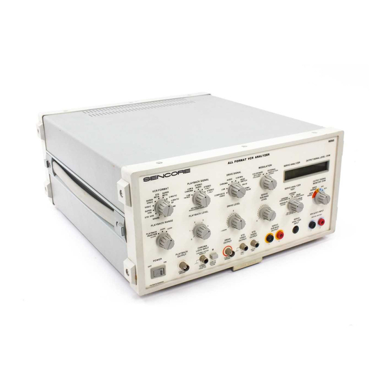
Learning To Use The VC93 All Format VCR Analyzer
The VC93 All Format VCR Analyzer provides
the necessary signals to troubleshoot the
luminance, chroma, and audio stages of a
VCR. It allows you to inject known good
signals to help isolate problems to the defec-
tive stage. The VC93 also provides special
Servo Analyzer Tests to help isolate servo
problems.
This Tech Tip will familiarize you with the
VC93 signals and servo tests, and where to
use them when servicing VCRs. Information
on troubleshooting specific VCR circuits is
covered in other Tech Tips.
This Tech Tip is organized according to the
major features of the VC93. You should have
the Universal VCR Block Diagrams provided
Table 1 - Key VCR Format Characteristics
with your VC93 manual for reference as you
read through this Tech Tip.
VCR FORMAT
There are many different VCR formats. The
main difference between each is the makeup
of the signals that are recorded onto the tape.
These differences include luminance frequen-
cies, the color-under signal, and the audio
frequencies used for Hi-Fi Stereo. Table 1
summarizes the key characteristics of each
VCR format supported by the VC93. The
VC93 provides signals to troubleshoot all
color-under format VCRs. Tech Tip 189,
"Comparison Of VCR Formats," provides a
more detailed discussion of each format.
The VC93's VCR FORMAT switch
sets the signals to match the
VCR format you are servicing. It
determines the makeup of the
luminance, chroma, and audio
signals coming from the PLAY-
BACK OUTPUT jack, and selects
the frequency of the "Head
Switch" DRIVE SIGNAL. Set VCR
FORMAT switch to match the
type of VCR you are servicing.
PLAYBACK SIGNAL
The VC93's PLAYBACK SIGNAL
switch and PLAYBACK OUTPUT
jack provide the proper signals
for injecting into the stages be-
fore the FM luminance detector,
chroma frequency convertor, and
FM audio detector. The test points
that require the use of the Play-
back Signals are summarized in
Table 2.
Note: The VCR FORMAT switch
must be set to the proper format
for the playback signals to be
correct at the PLAYBACK OUTPUT jack.
The PLAYBACK SIGNAL switch selects the
type of signal available at the PLAYBACK
OUTPUT jack. The peak-to-peak level of each
signal is adjustable with the PLAYBACK
RANGE and PLAYBACK LEVEL controls. Use
the HEAD SUBSTITUTION TEST LEAD to
inject any of the Playback Signals into the
appropriate test point. Following is a sum-
mary of each Playback Signal.
Luminance And Chrominance Signals
LUM (FM Modulated): This signal duplicates
the FM modulated luminance portion of the
signal found in the luminance stages of a VCR
or camcorder. It does not include the color
information. Injecting the FM LUM signal into
working VCR stages produces only the black
and white portion of the video pattern. Use
this signal to check the video heads, pre-
amps, and other FM luminance stages.
LUM & CHROMA: This signal includes both
the FM luminance and down-converted
chroma. Injecting the LUM CHROMA sig-
nal into a working VCR produces the COLOR
BARS pattern, or the pattern selected by the
"External" position of the MODULATION con-
trol if the VC93 is phase locked to the VCR.
This signal can also be injected into the FM
luminance stages, but its main application is
to phase lock the VCR to the VC93 while
injecting into the chroma circuits.
How To Phase Lock The VC93 To A VCR
For Color Troubleshooting
The chroma signal in color-under VCR for-
mats is phase shifted each video field to
minimize color crosstalk. The phase shifting
is controlled by the SW30 signal. In order for
the VCR to reproduce color when a signal
from the VC93 is injected into it, the color
phase generated by the VC93 must match the
Advertisement

Related Manuals for Sencore VC93


Summary of Contents for Sencore VC93
- Page 1 BARS pattern, or the pattern selected by the “External” position of the MODULATION con- PLAYBACK SIGNAL trol if the VC93 is phase locked to the VCR. This signal can also be injected into the FM The VC93's PLAYBACK SIGNAL luminance stages, but its main application is...
- Page 2 But unless the VC93 is phase locked VCR FORMAT switch automatically selects 4. Connect the HEAD SUBSTITUTION TEST to the VCR’s SW30, the VC93 may be produc- the proper signal makeup of the playback FM LEAD to the desired test point.
-
Page 3: Drive Signal
When the VCR FORMAT switch is set to VHS-C or SUPER VHS-C the Table 2 summarizes where to inject the VC93 HEADSWITCH Drive Signal frequency is Playback Signals on the Universal VCR Block 15 Hz. The frequency is 30 Hz for all other Diagrams. - Page 4 PUT SIGNALS jack on the VA62 or VA62A. contains the defect. 2. Set the DRIVE LEVEL to "0". Table 3 shows where to inject the VC93 STD VIDEO And STD AUDIO 3. Connect the DIRECT TEST LEAD to the Drive Signals on the Universal VCR Block DRIVE OUTPUT jack.
- Page 5 1. Connect the Performance Test Lead to tests starting with the "Ser- vos Locked" test and con- Table 3: Inject the VC93 Drive Signals at these Universal VCR tinue clockwise through all 2. Connect the yellow VIDEO phono plug Block Diagram test points.
- Page 6 Measuring Drive Signals And voltagespeciallydesigned fortroubleshooting servo External DCV And PPV circuits. The voltage is var- ied with the SERVO SUB The autoranged DVM monitors the internal BIAS LEVEL control. The Drive Signals, Servo Sub Bias, and external level is displayed in the voltages.
Need help?
Do you have a question about the VC93 and is the answer not in the manual?
Questions and answers