
Related Manuals for Sencore DSA 1491


Summary of Contents for Sencore DSA 1491
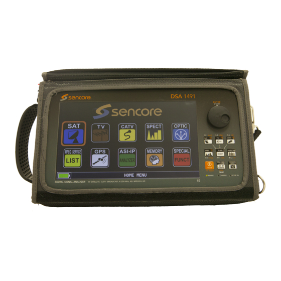
- Page 1 DSA 1491 Professional Multi-stream Satellite, Broadcast TV, CATV, ASI, IPTV DIGITAL SIGNAL ANALYZER User Manual August 2020 Form 8146 www.sencore.com | 1.605.978.4600 Revision 1.1...
- Page 2 This document may also have links to third-party web pages that are beyond the control of Sencore. The presence of such links does not imply that Sencore endorses or recommends the content on those pages. Sencore acknowledges the use of third-party open source software and licenses in some Sencore products.
- Page 3 `DSA 1491– User Manual Revision History Date Version Description Author 11/30/2015 Operations Manual for DSA 1491 G.A.K. 8/4/2020 Updated Package Contents M.D.H. Page 3 (192)
-
Page 4: Table Of Contents
`DSA 1491– User Manual Table of Contents INTRODUCTION ............................8 ....................... 8 ACKAGE ONTENTS USB C ....................... 9 ONTENTS SMART S ......................9 OFTWARE ....................9 YSTEM NFORMATION SECTION 1: UNIT FAMILIARIZATION ....................10 1.1 F ................10 RONT ANEL AMILIARIZATION 1.2 R... - Page 5 `DSA 1491– User Manual 3.24 CATV Configuration ........................39 3.24.1 LNB L.O.............................. 39 3.24.2 C/N TYPE ............................39 SECTION 4: SATELLITE MEASUREMENTS ..................44 4.1 S ................... 44 ATELLITE ELECTION 4.2 S ..................45 ATELLITE EASUREMENTS 4.21 Main Measurement Page ......................45 4.22 Satellite Analog Main Measurement Page ...................46...
- Page 6 `DSA 1491– User Manual 5.62 Spectrum Analyzer Marker Bandwidth Measurement ..............93 5.63 Spectrum Analyzer Delta Marker Measurement ................93 5.7 TV S ..................95 PECIAL UNCTIONS 5.71 TV BUZZER & NOISE MARGIN GRAPH TEST .................96 5.72 TV ATTENUATION TEST ......................97 5.8 TV M ...................
- Page 7 `DSA 1491– User Manual 7.3 A ....................147 UDIO IDEO SECTION 8: ASI MEASUREMENTS ....................148 8.1 ASI OUTPUT – D TV- RF ASI OUTPUT ......... 148 EMODULATED 8.2 ASI INPUT MPEG M ............149 ONITORING ESTING 8.21 ASI Input - MPEG Service List Page Description ..............149 8.22 TV MPEG Video Service Monitoring ..................150...
-
Page 8: Introduction
USB cable and SMART software. Package Contents Great care is taken to ensure the DSA 1491 shipped from the Sencore factory is free of defects, contains the supplied accessories and is securely packaged. Please inspect the package and contents upon receipt. If there has been significant damage please contact Sencore Inc. -
Page 9: Usb Contents
SMART Software Users Guide which provides instructions on how to install, license, connect and use the SMART software. The USB drive further contains a driver file used for the USB connection from the PC to the DSA 1491 when establishing a connection for the SMART software. -
Page 10: Section 1: Unit Familiarization
`DSA 1491– User Manual Section 1: Unit Familiarization 1.1 Front Panel Familiarization Ref. Main Function Description Second Function Color LCD Display with Shows all icons, setup, test data, Select menu items or tests by touch screen menus, information, touching the screen Control Wheel –... -
Page 11: Right Side Panel Familiarization
Indicates AC power present to AC Main Indicator meter 1.2 Right Side Panel Familiarization The right side panel of the DSA 1491 contains several interface connection jacks along with an air intake fan and internal speaker. The following section provides a brief description. Ref. -
Page 12: Top Side Panel Familiarization
`DSA 1491– User Manual 1.3 Top Side Panel Familiarization The top side panel of the DSA 1491 contains most of the input/output interface connection jacks. It further includes a switch and DVB-C CAM receptacle. The following section provides a brief description. -
Page 13: Home Menu Icon Familiarization
`DSA 1491– User Manual 1.4 Home Menu ICON Familiarization The Home Menu of the DSA 1491 is the first menu you see when powering on the meter. You may return to this menu from any other menu by briefly pressing the HOME pushbutton. - Page 14 `DSA 1491– User Manual D: SPEC: Touch to view spectrum analyzer display for frequency spectrum viewing of the currently selected satellite, TV or cable measurement channel/transponder(s). E. OPTIC: Optional Feature: Touch for measurements of the optical input power and power loss when comparing the active input power to a saved reference power level.
-
Page 15: Powering On/Off
1.6 Power Adapter The DSA 1491 is supplied with a DC power supply that is used to power the instrument and to indirectly charge its internal battery. The power supply/adapter is a regulated 12 VDC with a positive center terminal on the connector to the instrument. The power supply is rated for ACV inputs ranging from 100-240 VAC @ 50/60 Hz and can deliver up to 3.0 amp of DC output current. - Page 16 Some charging management practices may extend the battery pack’s useful life. Also the DSA 1491’s power management features may provide added use time on a single charge. This section covers the meter’s battery condition indicator, battery charging recommendations and battery power management features.
-
Page 17: Battery Replacement
You need to be absolutely sure you have the proper replacement Li Po battery pack for your DSA 1491. Sensing wires to the battery pack are critical in battery charging/discharging and safety. ONLY an exact replacement or a suitable replacement battery provided from Sencore should be used. - Page 18 `DSA 1491– User Manual discharge the battery and take it to a designated collection point in your area. Never dispose in a household or business waste collection. Page 18 (192)
-
Page 19: Section 2: Quick Start Guide
Section 2: Quick Start Guide 2.1 Navigation The DSA 1491 features a touch sensitive screen but supplements operation with a mechanical control knob and mechanical front panel switches. In combination, they are used to navigate, make selections, and initiate tests. The ability to make selections directly from the screen with a finger touch greatly simplifies meter use. - Page 20 `DSA 1491– User Manual Page 20 (192)
-
Page 21: Navigation - Exercise
DC@RF IN DIGITAL SIGNAL ANALYZER MULTISTREAM SAT, TV, CATV, OPTICAL, IP, ASI, 4-2250 MHz, MPEG2/4 HD To become familiar with the DSA 1491’s navigation follow the steps below: (#s reference fingers in the diagram above.) (Display Graphics Color Setting = BLUE) 1. -
Page 22: Dropdown Menu Selections
FREQ selection in the MEAS menu. These require use of the Control Knob to increment through selections. 2.3 Dropdown Menu Selections Several fields within the DSA 1491 screen have dropdown menus in which selections or entries are made. This section briefly explains how to select or enter values within a drop down menu. - Page 23 `DSA 1491– User Manual Frequency Selection Entry CHAN PLAN MODULAT CONST DC@RF FREQ The FREQ field provides a drop down USABRO 8VSB 201.00 menu which provides direct entry of a desired frequency. Touch the INSERT FREQ. frequency value below the FREQ...
-
Page 24: Measurement Signal Selection
`DSA 1491– User Manual 2.4 Measurement Signal Selection This section introduces you to the general operational layout of the DSA 1491 to improve your understanding and operational ease. The instrument is fundamentally divided into 3 major categories by signal type. The signal types are Satellite (SAT), Broadcast Television (TV) and Cable Television (CATV). -
Page 25: Quick Start Measurements
TV or cable measurements. It is not intended to completely summarize all the information contained in this manual. Please reference other portions of the manual as needed to answer questions and become familiar with the DSA 1491 and its features. -
Page 26: Entering Field Values
`DSA 1491– User Manual 2.7 Entering Field Values Some field values in the DSA 1491 are entered with a popup entry menu. This menu presents several entry boxes in the center of the display screen area. The number of fields or boxes represent the number of digits available for entry. -
Page 27: Section 3: Meter Configuration
`DSA 1491– User Manual Section 3: Meter Configuration The DSA1490 has two meter configuration menus. They include an initial CONFIG Pushbutton or “Quick View” menu and an extended CONFIGURATION MENU. The Quick View menu is accessed by briefly touching the CONFIG pushbutton at the bottom right corner of the meter. -
Page 28: Brightness
`DSA 1491– User Manual 3.12 BRIGHTNESS The BRIGHTNESS field adjusts the display backlight setting resulting in an increase or decrease in the display’s brightness. Keep in mind, that the brighter the display setting the faster the internal battery pack discharges reducing the portable use time. -
Page 29: Image Format
OPTICAL IN jack. 3.18 LTE FILTER The LTE FILTER is an optional feature that is not provided with the DSA 1491. The LTE FILTER field option when installed provides control to switch in an LTE band filter into the input RF measurement signal path. -
Page 30: Battery Saving
The BATTERY SAVING field provides control to either turn ON or turn OFF the battery saving features of the meter. The DSA 1491 provides two battery saving features. When the BATTERY SAVING setting is in the ON mode, if no user key press or touch command is received for a period of 30 seconds, the display brightness is reduced. -
Page 31: Configuration Menu
`DSA 1491– User Manual 3.2 Configuration Menu The CONFIGURATION MENU provides setup options for the meter and measurement functions. The CONFIGURATION MENU is accessed by first pressing the CONFIG pushbutton at the bottom right of the meter’s front panel. Secondly, touch the CONFIGURATION MENU listing near the bottom of the Quick View Config. - Page 32 `DSA 1491– User Manual life. To set, navigate to the CONFIGURATION MENU and touch the METER field. Then touch the TIMER OFF listing followed by touches to the highlighted field at the right to select the desired time delay. The settings include: OFF (meter always on), 5 min (meter turns off in 5 minutes), 10 min (meter turns off in 10 minutes), 15 min (meter turns off in 15 minutes), 30 min (meter turns off in 30 minutes)..
- Page 33 3.21.7 BATTERY TEST The BATTERY TEST field provides an automated battery test and reconditioning routine performed by the DSA 1491. The feature performs an internal battery test. The BATTERYTEST checks/recovers the battery capacity and recalculates the meter’s battery charge indicator to get precise Indications on the charge battery status. For example, if the battery test indicates “000255000,”...
- Page 34 3.21.12 LAN CONFIGURATION The LAN CONFIGURATION field provides selections to configure the RJ45 or LAN connection port of the DSA 1491 for connection to a network. The menu provides selection for a DHCP (Dynamic Host Connection Protocol) IP connection/configuration or static connection/configuration.
-
Page 35: Tv Configuration
`DSA 1491– User Manual 3.22 TV Configuration The TV listing provides settings CONFIGURATION MENU relative to the terrestrial TV LNB L. 0. : 0 MHz METER measurements provided by the DSA OUT BAND C/N TYPE: 1491. To access the TV field TERR. -
Page 36: Sat Configuration
3.22.4 FIELD STRENGTH & EDIT ANT. FACTOR The FIELD STRENGTH field provides several selections of antenna types designed for use with the DSA 1491 for making TV transmission field strength measurements. Or, you may use an alternate antenna and select the CUSTOM antenna selection. When the CUSTOM selection is choosen the EDIT ANT. -
Page 37: Ku Band
`DSA 1491– User Manual using the KU BAND or C BAND local oscillator setting entered into the meter. See the next two sections. If the O MHz (IF) selection, the meter performs no conversion and assumes you are inputting an L-BAND IF signal for measurement. For common satellite dish installations and signal analyzing use the STANDARD setting. -
Page 38: Lnb 2 Diseqc
Touch the LNB 1 DiSEqC field followed by touches to the highlighted field at the right to select the desired port (A, B,C, or D). Note: The Sencore provided DiSEqC switch is a two port switch with A and B port selections. -
Page 39: Catv Configuration
`DSA 1491– User Manual 3.24 CATV Configuration CONFIGURATION MENU The CATV listing provides settings LNB L. 0. : 0 MHz METER relative to using the CATV C/N TYPE: OUT BAND measurements provided by the DSA CABLE ONLY SAT: DISCOVERY: 1491. To access the CATV field... - Page 40 `DSA 1491– User Manual BAND,” The signal/noise ratio is measured between the signal level of the video carrier and the noise level estimated in the guard band (-1.250 MHz from the video carrier. To select the C/N TYPE, navigate to the CONFIGURATION MENU and touch the METER field.
- Page 41 MONITOR, and NETWORK DELAY MEASUREMENT are not currently available. Some options on the list are provided courtesy of Sencore and are not additional purchased options. Examples include the TV MINISPECTRUM, ASI IN/OUT and HD AUDIO DOLBY +. These options are included with every DSA 1491.
- Page 42 The CONFIG LAN IPTV selection provides a menu used to configure the TS Over IP LAN RJ45 jack or connection port of the DSA 1491 for connection to a network. The static configuration provides entry of IP, Network Mask and Gateway address entries.
- Page 43 The COMMON INTERFACE field provides a CONFIGURATION MENU selection to provide information regarding METER the Conditional Access Smart Card Reader. The DSA 1491 contains a CI or Common STATUS NOT PRESENT SAT: Interface Slot on the right side of the meter.
-
Page 44: Section 4: Satellite Measurements
4.1 Satellite Plan Selection The DSA 1491 is a satellite receiver which may be tuned to the individual satellite transponders. A comprehensive list of satellites with tuning information is contained in the satellite plan of the instrument. When the SAT icon is highlighted on the Home Menu, press the PLAN SELECT pushbutton on the unit’s front panel. -
Page 45: Satellite Measurements
MEAS icon in the Satellite Plan Selection Menu. There are two satellite measurement pages for digital satellite signals including a main measurement page and a constellation measurement page. The remainder of this section describes the DSA 1491’s satellite measurements and measurement pages. 4.21 Main Measurement Page TRANSP... -
Page 46: Satellite Analog Main Measurement Page
`DSA 1491– User Manual 3. DiSEqC: The current setting for DiSEqC to provide switching signals for satellite equipment 4. Polarity/Band: Vert./Horiz (Left/Right) polarization, high/low band switching and 12V or 18V indicator. Selectable field permits polarity/band selection. 5. Frequency: The center frequency of the satellite transponder (6). Selectable field permits frequency tuning. - Page 47 `DSA 1491– User Manual constellation analysis. The right center of the Constellation & Info page provides an INFO box with information regarding the satellite transponder signal and satellite dish/system being measured. There are two ways to access the Constellation & Info measurement page form the Main Measurement page.
- Page 48 `DSA 1491– User Manual PER: Packet Error Rate analysis PILOT: Pilot on/off indicator * NOTE: Measurements provided depend on the satellite signal type and inclusion of the test codes required for the tests. Page 48 (192)
-
Page 49: Satellite Mpeg Service List
`DSA 1491– User Manual 4.3 Satellite MPEG SERVICE LIST The MPEG SERVICE LIST measurement page of the DSA 1491 provides information regarding the MPEG stream and video service/program of the selected satellite transponder. The MPEG SERVICE LIST page may be accessed in two ways. From the HOME Menu with the SAT icon highlighted, touch the MPEG SERVICE LIST icon. -
Page 50: Mpeg Video Service Monitoring
`DSA 1491– User Manual 4.32 MPEG Video Service Monitoring The video displayed in the Main Measurement Page or in the MPEG SERVICE LIST page may be expanded to fill the display screen. For a full screen view of the demodulated video of a selected video service touch the displayed video section of the screen. -
Page 51: Dvb-S2 Multi Stream Selection Popup Menu
`DSA 1491– User Manual VISUALIZE NIT: Provides a measurement screen with the information contained in the DVB Network Information Table. CHANNEL LOGGER: Monitors and charts the digital RF measurements of a satellite transponder or channel. ASI icon: Provides a shortcut to the ASI-IP analyzer function providing an TS stream bitrate and services information. -
Page 52: Satellite Spectrum Analyzer
`DSA 1491– User Manual 4.5 Satellite Spectrum Analyzer The satellite spectrum analyzer provides detailed spectral analysis of both analog and digital satellite signals. To select the spectrum analyzer function from the HOME menu with the SAT icon highlighted, touch the SPEC icon. You may also access the spectrum analyzer from any of the other satellite measurement pages by pushing the SPEC pushbutton at the right of the display. -
Page 53: Satellite Spectrum Analyzer Popup Menu
`DSA 1491– User Manual 10. Marker Power: The power indicated at the frequency location of the marker line. The field is not selectable. SPECTRUM MENU 4.6 Satellite Spectrum Analyzer Popup Menu FAST SPECTRUM : BUZZER : The satellite Spectrum Analyzer page includes a popup menu MRK. - Page 54 `DSA 1491– User Manual SAVE/RECALL: Provides memory for 20 captured spectrum analyzer screens which may be recalled and viewed on the screen. HELP ICON: Provides signal DISCOVERY to automatically determine a digital satellite transponders signal type, modulation type, and symbol rate for automatic tuning.
-
Page 55: Satellite Special Functions
`DSA 1491– User Manual 4.7 Satellite Special Functions The DSA 1491 provides many special SPECIAL FUNCTIONS functions for satellite dish control and alignment. The satellite special functions SAT SCR menu is selected by pressing the SPECIAL DUAL LNB FUNCT icon on the HOME Menu with the SAT icon highlighted. - Page 56 `DSA 1491– User Manual Page 56 (192)
-
Page 57: At Scr - Single Cable Router Test Function
The test works in conjunction with the dual DiSEqC switch that is provided with the DSA 1491. To select the DUAL LNB test from the HOME Menu, with the SAT icon highlighted, touch the SPECIAL FUNCT icon. From the SATELLITE PLAN SELECTION MENU, touch the SPECIAL FUNCT icon. - Page 58 RF input. Set the LNB 1 DiSEqC setting (A, B, C, D): IN 1 = DiSEqC “A” on the Sencore Switch). Set to correspond to the switch input you want to meter for IN/LNB 1. Set the LNB 2 DiSEqC setting (ABCD: IN 2 = DiSEqC “B” on the Sencore provided switch).
-
Page 59: Diseqc - Dish Motor Control Function
`DSA 1491– User Manual 4.73: DiSEqC – Dish Motor Control Function The DiSEqC MOTOR is a special function which permits measurement of a satellite signal while also providing DiSEqC motor actuator commands to move the dish. To select the DiSEqC MOTOR special test from the HOME Menu, with the SAT icon highlighted, touch the SPECIAL FUNCT icon. -
Page 60: Sat Finder Function
`DSA 1491– User Manual 4.74 SAT FINDER Function The SAT FINDER is a special function which is used to find and verify if you have a satellite dish aimed at the proper satellite. The SAT FINDER looks for three user-defined reference transponders on the selected satellite. - Page 61 2. Touch the SAT icon on the HOME or start Menu of the DSA 1491. In the next menu, (SATELLITE PLAN SELECTION MENU) touch the desired satellite to select it. Note: touch at the top or bottom of the list to scroll up or down.
-
Page 62: Buzzer & Noise. Margin Graph Function
`DSA 1491– User Manual 4.75 BUZZER & NOISE. MARGIN GRAPH Function The BUZZER & NOISE MARGIN GRAPH test, abbreviated BUZZ&NOIS. MAR. GR. is a special function which provides a time charted graph of the Noise Margin measurement of a selected satellite transponder. It further is accompanied by the alignment buzzer. -
Page 63: Multi-Freq L-Band Function
`DSA 1491– User Manual 4.76 MULTI-FREQ L-BAND FUNCTION The MULTI-FREQ L-BAND test is a test that simultaneously measures the signal power of three L-Band frequencies and meters the attenuation of the signals compared to a reference or “calibrated” level. The test may be used to determine L-Band loses between tow signal points. -
Page 64: Sat Pointer Function
`DSA 1491– User Manual LNB SUPPLY: This field provides polarity and band selections if needed to provide for the satellite dish or equipment. 4.77 SAT POINTER Function The SAT POINTER special function provides a satellite spectrum analyzer view of the selected satellite transponder. -
Page 65: Azimuth & Elevation
`DSA 1491– User Manual 4.78 Azimuth & Elevation The Azimuth & Elevation special function is a satellite calculator for eastern hemisphere satellite dish azimuth, elevation, polarization, and polar dish settings. Enter in the satellite dish installation location including the orbit position... - Page 66 `DSA 1491– User Manual Slant Range: Distance in kilometers Polarization Tilt: Polarization tilt setting in degrees Polar Axis Angle: Polar axis angle setting in degrees Polar Offset Tilt: Polar offset tilt angle in degrees Page 66 (192)
-
Page 67: Satellite Memory Management
`DSA 1491– User Manual 4.8 Satellite Memory Management The MEMORY MENU provides test logging features and MEMORY MENU MEMORY transponder/channel management functions. The AUTOMEMORY tv MEMORY MENU is accessed by pressing the MEMORY icon with the head/brain picture on it. On the Home Menu... - Page 68 `DSA 1491– User Manual DATALOGGER listing in the MEMORY MENU. The SAVE DATALOGGER has a configuration menu with several fields which impact the function. Following is a brief description of these fields. FROM FILE: This field indicates the selected satellite in a satellite or manual memory plan.
-
Page 69: Recall Datalogger - View Satellite Data Log File
`DSA 1491– User Manual 4.82 RECALL DATALOGGER - View Satellite Data Log File The RECALL MEMORY MEMORY MENU DATALOGGER within the MEMORY MENU provides AUTOMEMORY tv DATA FILE: LOG. 1 a means to recall existing SAVE DATALOGGER POINT 1 Point:... -
Page 70: Manumemory - Creating Or Editing Satellite Plans
`DSA 1491– User Manual 4.83 MANUMEMORY – Creating or Editing Satellite Plans The MANUMEMORY feature found in the MEMORY MENU provides the ability to manually create a tuning plan which may includes a list of satellite transponders. A manual plan provides convenience by listing only the transponders you want to test or that you use for your installations. -
Page 71: File Manager - Renaming Or Deleting Files
`DSA 1491– User Manual MODIFY ITEM: Produces the ITEM EDITING menu which permits changes to the settings for the transponder listing highlighted ADD BELOW: Produces the ITEM EDITING menu in which you may select the parameters of a transponder signal and dish characteristic to add a listing below the currently highlighted field. - Page 72 `DSA 1491– User Manual SELECT ITEM MEMORY MEMORY MENU ACTION TYPE NAME SIZE RENAME FILE AUTOMEMORY tv LOG. 1 2300 DELETE FILE 1368 SAVE DATALOGGER AUTO AUTO 2 AUTO AUTO 1 2328 RECALL DATALOGGER MANU MANU 2 MANUMEMORY MANU MANU 3...
-
Page 73: Satellite Help
`DSA 1491– User Manual 4.9 Satellite HELP The HELP icon of the DSA 1491 within the Satellite Spectrum Analyzer popup menu offers automated help in tuning to a satellite transponder. The HELP icon on the DSA 1491 refers to help or assistance tuning in a digital channel. The HELP feature determines for a user the RF type of digital signal within a satellite transponder. -
Page 74: Satellite Ts Streaming Lan/Usb
`DSA 1491– User Manual 4.10 Satellite TS Streaming LAN/USB The TSstreaming feature permits streaming of the demodulated transport stream of the received satellite, cable or broadcast signal. The TS streaming feature can be used to stream the selected transport steam services to a destination IP address via the TS Over IP LAN port. - Page 75 `DSA 1491– User Manual Data Rate: Indicates the data rate of the stream via LAN. (Rate is limited to 20 Mbps) Note: The streaming LAN feature does not provide professional TS stream muxing and PCR correction so use should be limited to signal confirmation and monitoring only.
-
Page 76: Satellite - Visualize Nit
`DSA 1491– User Manual 4.11 Satellite – Visualize NIT The DSA 1491 provides an information page of the data found in a DVB satellite signal’s NIT (Network Information Table). To view the NIT information, touch the MENU & ? field and touch the VISUALIZE NIT listing. - Page 77 `DSA 1491– User Manual The Single Channel Monitoring screen is divided into a top and bottom chart or graph. Each graph includes multiple channel measurements as described below: Top Chart: The top chart of the monitoring screen provides charted values which include 3 measurements on a single chart.
- Page 78 `DSA 1491– User Manual Page 78 (192)
-
Page 79: Tv Plan Selection
`DSA 1491– User Manual Section 5: TV Broadcast Measurements The broadcast TV signal analysis provided by the DSA 1491 indicates the performance of broadcast television digital 8VSB signals or ISDB-T or DVB-T/T2, depending on model. Measurements provide guidance for antenna installation/aiming and may be used to test TV-RF distribution systems. -
Page 80: Tv Digital & Analog Measurements
TV pushbutton or the MEAS icon at the right. The meter advances to the TV MEASUREMENT page. 5.2 TV Digital & Analog Measurements The DSA 1491 provides a comprehensive analysis of a TV broadcast signal, either digital or analog. Digital signal analysis includes standard 8VSB, ISDB-T, or DVB-T/T2 analysis depending on the model. -
Page 81: Analog Tv Measurements
Modulation Error Ratio measurement of selected channel 21. POWER: Average Power measurement for the digital channel and video carrier peak measurement for an analog channel, typically in dBmV. 5.22 Analog TV Measurements The DSA 1491 may be used to CHAN PLAN MODULAT AUDIO... -
Page 82: Fm Radio Tuning & Measurement
`DSA 1491– User Manual the AN.TV listing. In most instances the meter detects when the channel is not a digital channel and defaults to the analog “AN. TV” type. Analog measurements are provided on two measurement pages. Push the TV front panel push button to increment to each measurement page. -
Page 83: Tv Mpeg Service List
`DSA 1491– User Manual 5.3 TV MPEG SERVICE List The MPEG SERVICE LIST measurement page of the DSA 1491 provides information regarding the MPEG stream and video service/programs of the selected TV channel. The MPEG SERVICE LIST page may be accessed in two ways. From the HOME Menu with the TV icon highlighted, touch the MPEG SERVICE LIST icon. -
Page 84: Tv Constellation & Monitoring
`DSA 1491– User Manual 5.32 TV Constellation & Monitoring The constellation measurement page provides a second page of analysis of a broadcast digital channel. The top and bottom fields of the page are the same as the main measurement page. The left center of the Constellation &... -
Page 85: Tv Mpeg Video Service Monitoring
`DSA 1491– User Manual 5.33 TV MPEG Video Service Monitoring The video displayed in the Main Measurement Page or in the MPEG SERVICE LIST page may be expanded to fill the display screen. For a full screen view of the demodulated video of a selected video service touch the displayed video section of the screen. -
Page 86: Tsstreaming
`DSA 1491– User Manual MINISPECTRUM: Provides a spectrum overlay on the displayed video in the video window on the measurement page. The Minispectrum can be enabled or disabled for digital measurement channels. VISUALIZE NIT: Provides a measurement screen with the information contained in the DVB Network Information Table. -
Page 87: Minispectrum
`DSA 1491– User Manual TS Streaming USB The TSstreaming feature may be used to stream the selected transport stream services to a USB memory stick. To start TSstreaming touch the MENU & ? icon at the bottom right of the measurement... -
Page 88: Visual Nit
OFF to enable or disable the spectrum overlay. 5.43 VISUAL NIT The DSA 1491 provides an information page of the data found in a DVB signal’s NIT (Network Information Table). To view the NIT information, touch the MENU & ? field and touch the VISUALIZE NIT listing. - Page 89 `DSA 1491– User Manual The DSA 1491 includes the ability to continuously monitor and chart the critical RF analyzing measurements of a broadcast over a selected time period. The charting allows you to see events or times of RF signal impairments or reception interruptions. To select the Channel Monitoring feature touch the MENU &...
-
Page 90: Tv Spectrum Analyzer
`DSA 1491– User Manual 5.5 TV Spectrum Analyzer The TV spectrum analyzer provides detailed spectral analysis of both analog and digital analog TV signals. To select the spectrum analyzer function from the HOME menu with the TV icon highlighted, touch the SPEC icon. You may also access the spectrum analyzer from any of the other measurement pages by pushing the SPEC pushbutton at the right of the display. - Page 91 `DSA 1491– User Manual The TV Spectrum Analyzer page contains header SPAN PLAN MODE REF. PWR MRK.FRQ CHAN fields with many USABRO DIGITAL 0 dBmV 593.00 of the same 0 dB sections as the 10 dB measurement SPEC 20 dB page.
-
Page 92: Tv Spectrum Analyzer Popup Menu
`DSA 1491– User Manual 5.6 TV Spectrum Analyzer Popup Menu The TV Spectrum Analyzer includes a popup menu that provides settings for the spectrum analyzer and provides handy features. It further provides a convenient access to the HELP function. Touch the MENU &... -
Page 93: Spectrum Analyzer Marker Bandwidth Measurement
`DSA 1491– User Manual HELP ICON: Provides signal analysis to automatically determine a digital broadcast signal type, modulation type, and symbol rate for automatic tuning. 5.62 Spectrum Analyzer Marker Bandwidth Measurement The Spectrum Analyzer includes a marker bandwidth (MRK.BW.) measurement. This measurement... - Page 94 `DSA 1491– User Manual point. The red marker is not moveable in the Delta Marker function. To select the DELTA MARKER function touch the MENU&? field and in the popup menu touch the Delta (Triangle) Marker listing so it indicates “ON.”...
-
Page 95: Tv Special Functions
`DSA 1491– User Manual 5.7 TV Special Functions The TV Special Functions menu provides several SPECIAL FUNCTIONS listings. The TV special functions menu is selected BUZZ & NOIS. MARG. GR. by pressing the SPECIAL FUNCT icon on the HOME Menu when the TV icon is highlighted. This... -
Page 96: Tv Buzzer & Noise Margin Graph Test
`DSA 1491– User Manual 5.71 TV BUZZER & NOISE MARGIN GRAPH TEST The BUZZER & NOISE MARGIN GRAPH test, abbreviated BUZZ&NOIS. MAR. GR, is a special function which provides a time charted graph of the Noise Margin measurement of a selected satellite transponder. It further is accompanied by the alignment buzzer. -
Page 97: Tv Attenuation Test
`DSA 1491– User Manual 5.72 TV ATTENUATION TEST The TV ATTENUATION TEST is a special test that simultaneously measures the signal power of three TV frequencies and meters the attenuation of the signals compared to a reference or “calibrated” level. The test may be used to determine attenuation or loses between two signal points. -
Page 98: Tv Memory Management
`DSA 1491– User Manual 5.8 TV Memory Management The MEMORY MENU provides channel plan creating, MEMORY MENU MEMORY test logging features and channel plan management AUTOMEMORY tv functions. The MEMORY MENU is accessed by pressing the MEMORY icon with the head/brain picture on it. On... - Page 99 `DSA 1491– User Manual Auto scanning channels and creating a channel plan provides the convenience of only listing the channels available in your area for meter selection. All inactive channels are removed from the channel plan. Auto scanning channels to create a channel plan further configures each available channel as either analog or digital so the meter automatically applies the proper signal measurements.
-
Page 100: Save Datalogger - Tv Auto Measure & Store
`DSA 1491– User Manual 5.82 SAVE DATALOGGER – TV Auto Measure & Store The SAVE DATALOGGER feature within the MEMORY MENU scans the channels in a selected channel plan and captures MEMORY MENU performance measurements for each channel to a log file. The... - Page 101 `DSA 1491– User Manual LOGGER FUNCTION screen the transponder currently being tested is highlighted. A picture indication shows if the transponder was digital or analog. Page 101 (192)
-
Page 102: Recall Datalogger - View Tv Data Log File
`DSA 1491– User Manual 5.83 RECALL DATALOGGER - View TV Data Log File The RECALL MEMORY DATALOGGER within the MEMORY MENU MEMORY MENU provides AUTOMEMORY tv DATA FILE: LOG. 1 a means to recall existing SAVE DATALOGGER POINT 1 Point:... -
Page 103: Manumemory - Creating Or Editing Tv Channel Plans
`DSA 1491– User Manual 5.84 MANUMEMORY – Creating or Editing TV Channel Plans The MANUMEMORY feature found in the MEMORY MENU provides the ability to manually create a tuning plan which may include a list of broadcast channels. The file containing the active channels is named as a MANU plan with a numeric reference (Example: MANU 1). - Page 104 `DSA 1491– User Manual ACTIVE PLAN: MANU 25 TR/CHAN FREQ MODE ITEM EDITING 201.0 8VSB 8 VSB MODE 213.0 8VSB 479.0 8VSB ACTION CHAN: 605.0 8VSB FREQ: 201 MHz MODIFY ITEM 731.0 8VSB AUDIO: 4.5 FM ADD BELOW NAME PR 1...
- Page 105 `DSA 1491– User Manual Press BACK to return to the previous menu without making changes. Page 105 (192)
-
Page 106: Tv File Manager - Renaming Or Deleting Files
`DSA 1491– User Manual 5.85 TV FILE MANAGER – Renaming or Deleting Files The FILE MANAGER, found in the MEMORY MENU, provides management of the logger and transponder/channel plan files. The FILE MANAGER provides the ability to rename or delete files from the meter’s memory. To access the FILE MANAGER from the Home Menu, touch the MEMORY icon followed by a touch of the FILE MANAGER listing in the MEMORY MENU. -
Page 107: Tv "Help" Signal Discovery
5.9 TV “Help” Signal Discovery The HELP icon on the DSA 1491 refers to help or assistance tuning in a digital channel. The HELP function is used to help determine for a user the RF type of signal within a TV broadcast channel. -
Page 108: Tv Bar Scan Test
`DSA 1491– User Manual 5.10 TV BAR SCAN Test The BAR SCAN measurement shows multiple bars forming a bar chart. Each bar of the chart represents the level of a TV-RF channel. The Bar Scan is essentially a simplified spectrum display in which multiple channel levels through a frequency span are indicated with bars on a level chart. - Page 109 `DSA 1491– User Manual 1. PLAN: Indicates the channel plan selected for measurement. The plan includes the channel list that will be measured and plotted into the BAR SCAN test results. 2. REF PWR Reference Power: The reference value establishes the level of the top horizontal bar of the bar graph.
-
Page 110: Section 6: Catv Measurements
MENU contains several listings of which to choose from. The following is a brief description of these listings and their content. These cable plan listing depend on the DSA 1491 model and are appropriate for different locations. CATV MASTER PLAN:... -
Page 111: Catv Digital Measurements
There are two CATV measurement pages for digital cable signals including a main measurement page and a constellation measurement page. The remainder of this section describes the DSA 1491’s CATV measurements and measurement pages. The following section describes the fields as numbered in the nearby figure. - Page 112 `DSA 1491– User Manual 2. Modulation: The modulation type of the digital signal. Defaults to the type in the channel plan which should be J83-B (QAM B) for CATV in North America for the selected channel (6). Selectable field permits selection of other modulation types and analog (AN.TV).
-
Page 113: Analog Catv Measurement Page
`DSA 1491– User Manual 6.22 Analog CATV Measurement Page An analog NTSC cable CHAN PLAN MODULAT AUDIO DC@RF FREQ channel can be metered for TEST 1 AN. TV 55.25 signal level and the LEVEL: -1 dBm demodulated video may be... -
Page 114: Catv Constellation & Info Measurement Page
The digital signal standard annex it complies with such as J83-A which is the North American cable standard. SYM RATE: The rate of the RF symbols as measured by the DSA 1491. LNB Curr: Metered current flowing from the meter to the satellite dish LNB. - Page 115 `DSA 1491– User Manual Page 115 (192)
-
Page 116: Catv Mpeg Service List
`DSA 1491– User Manual 6.3 CATV MPEG SERVICE List The MPEG SERVICE LIST measurement page of the DSA 1491 provides information regarding the MPEG stream and video service/programs of the selected CATV channel. The MPEG SERVICE LIST page may be accessed in two ways. From the HOME Menu with the TV icon highlighted, touch the MPEG SERVICE LIST icon. -
Page 117: Catv Mpeg Video Service Monitoring
`DSA 1491– User Manual 6.32 CATV MPEG Video Service Monitoring The video displayed in the Main Measurement Page or in the MPEG SERVICE LIST page may be expanded to fill the display screen. For a full screen view of the demodulated video of a selected video service touch the displayed video section of the screen. -
Page 118: Tsstreaming
`DSA 1491– User Manual MINISPECTRUM: Provides a spectrum overlay on the displayed video in the video window on the measurement page. The Minispectrum can be enabled or disabled for digital measurement channels. VISUALIZE NIT: Provides a measurement screen with the information contained in the DVB Network Information Table. -
Page 119: Minispectrum
`DSA 1491– User Manual TS Streaming USB The TSstreaming feature may be used to stream the selected transport stream services to a USB memory stick. To start TSstreaming touch the MENU & ? icon at the bottom right of the measurement... -
Page 120: Visual Nit
OFF to enable or disable the spectrum overlay. 6.43 VISUAL NIT The DSA 1491 provides an information page of the data found in a DVB signal’s NIT (Network Information Table). To view the NIT information, touch the MENU & ? field and touch the VISUALIZE NIT listing. - Page 121 `DSA 1491– User Manual The DSA 1491 includes the ability to continuously monitor and chart the critical RF analyzing measurements of a broadcast over a selected time period. The charting allows you to see events or times of RF signal impairments or reception interruptions. To select the Channel Monitoring feature touch the MENU &...
-
Page 122: Catv Spectrum Analyzer
`DSA 1491– User Manual 6.5 CATV Spectrum Analyzer The CATV spectrum analyzer provides detailed spectral analysis of both analog and digital CATV signals. To select the spectrum analyzer function from the HOME menu with the TV icon highlighted, touch the SPEC icon. You may also access the spectrum analyzer from any of the other measurement pages by pushing the SPEC pushbutton at the right of the display. -
Page 123: Catv Spectrum Analyzer Popup Menu
`DSA 1491– User Manual The TV Spectrum Analyzer page contains header fields with many of the same sections as the measurement page. However, some of the headings are different. Below is a summary of all the header fields and an indication if the field may be highlighted for change. -
Page 124: Catv Spectrum Analyzer Delta Marker Measurement
`DSA 1491– User Manual measurement to the selected band at the bottom center of the spectrum analyzer display. DELTA MARKER: Turns on or off a white marker which along with the existing red marker provide two adjustable frequency locations. At the center bottom of the spectrum analyzer display is added a Delta Marker Power (Delta MRK.P) measurement which... -
Page 125: Spectrum Analyzer Marker Bandwidth Measurement
`DSA 1491– User Manual The Delta Marker measurement provides a frequency difference measurement and a level difference measurement between the location of the red marker and the white marker. The Delta Frequency is indicated under the MRK FR. Header. The Delta Marker power or level is indicated in the bottom center measurement field. -
Page 126: Catv Special Functions
`DSA 1491– User Manual 6.7 CATV Special Functions SPECIAL The CATV Special Functions menu provides SPECIAL FUNCTIONS several listings. The CATV Special Functions FUNCT. LEAKAGE Menu is selected by pressing the SPECIAL INGRESS FUNCT icon on the HOME Menu when the CATV REFLECTOMETER icon is highlighted. -
Page 127: Catv Leakage Test
`DSA 1491– User Manual 6.71 CATV LEAKAGE TEST The Leakage Test measures the field intensity of a signal(s) emitted or “leaking” from the shielded cable system. Elevated leakage levels indicate a shielding problem which should be corrected to prevent potential interference to other signal transmissions and avionics. - Page 128 `DSA 1491– User Manual NOTE: The Antenna Type selections result in three programmed antenna factors, 100 for the dipole, 90 for the monopole, and 75 for the rubber duck antenna. Distance The Distance setting compensations the Leakage measurement based upon the estimated distance from the leak source.
-
Page 129: Catv Ingress Test
`DSA 1491– User Manual 6.72: CATV INGRESS TEST The CATV Ingress Test is a special function which shows potential ingress interference problems in the upstream cable spectrum by providing a spectrum analysis from 5 to 65 Mhz. Connect the upstream cable signal to the RF input on the top left of the meter. - Page 130 `DSA 1491– User Manual NOTE: You may use the MENU & ? Popup Menu to gain access and adjust the spectrum analyzer’s ingress start and stop frequencies. Page 130 (192)
-
Page 131: Catv Buzzer & Noise Margin Graph Test
`DSA 1491– User Manual 6.73 CATV BUZZER & NOISE MARGIN GRAPH TEST The BUZZER & NOISE MARGIN GRAPH test, abbreviated BUZZ&NOIS. MAR. GR, is a special function which provides a time charted graph of the Noise Margin measurement of a selected satellite transponder. It further is accompanied by the alignment buzzer. -
Page 132: Catv Memory Management
`DSA 1491– User Manual 6.8 CATV Memory Management The MEMORY MENU provides channel plan creating, MEMORY MENU MEMORY test logging features and channel plan management AUTOMEMORY tv functions. The MEMORY MENU is accessed by pressing the MEMORY icon with the head/brain picture on it. On... - Page 133 `DSA 1491– User Manual To perform the MEMORY MENU AUTOMEMORYtv scan, with FROM PLAN: USABRO AUTOMEMORY tv the CATV icon highlighted on TO FILE N : AUTO 3 the HOME MENU touch the SAVE DATALOGGER LEVEL: MEMORY icon. The meter >...
-
Page 134: Save Datalogger - Catv Auto Measure & Store
`DSA 1491– User Manual 6. Wait a few minutes and watch the display screen which illustrates the scanning process and indicates the channels as discovered. The meter indicates complete when all the channels have been scanned. 6.82 SAVE DATALOGGER – CATV Auto Measure & Store... - Page 135 `DSA 1491– User Manual progress. A Total Test Report section, on the right of the display screen, indicates the progress of the scan and summarizes the performance of each transponder tested. The transponder is color coded in the report indicating a pass, marginal or fail status. Near the bottom of the LOGGER FUNCTION screen the transponder currently being tested is highlighted.
-
Page 136: Recall Datalogger - View Catv Data Log File
`DSA 1491– User Manual 6.83 RECALL DATALOGGER - View CATV Data Log File The RECALL MEMORY DATALOGGER within the MEMORY MENU MEMORY MENU provides AUTOMEMORY tv DATA FILE: LOG. 1 a means to recall existing SAVE DATALOGGER POINT 1 Point:... -
Page 137: Manumemory - Creating Or Editing Catv Channel Plans
`DSA 1491– User Manual 6.84 MANUMEMORY – Creating or Editing CATV Channel Plans The MANUMEMORY feature found in the MEMORY MENU provides the ability to manually create a tuning plan which may include a list of broadcast channels. The file containing the active channels is named as a MANU plan with a numeric reference (Example: MANU 1). - Page 138 `DSA 1491– User Manual ACTIVE PLAN: MANU 25 TR/CHAN FREQ MODE ITEM EDITING 201.0 8VSB 8 VSB MODE 213.0 8VSB 479.0 8VSB ACTION CHAN: 605.0 8VSB FREQ: 201 MHz MODIFY ITEM 731.0 8VSB AUDIO: 4.5 FM ADD BELOW NAME PR 1...
- Page 139 `DSA 1491– User Manual Page 139 (192)
-
Page 140: Catv File Manager - Renaming Or Deleting Files
`DSA 1491– User Manual 6.85 CATV FILE MANAGER – Renaming or Deleting Files The FILE MANAGER, found in the MEMORY MENU, provides management of the logger and transponder/channel plan files. The FILE MANAGER provides the ability to rename or delete files from the meter’s memory. To access the FILE MANAGER from the Home Menu, touch the MEMORY icon followed by a touch of the FILE MANAGER listing in the MEMORY MENU. -
Page 141: Catv Help
`DSA 1491– User Manual 6.9 CATV HELP The HELP icon on the DSA 1491 refers to help or assistance tuning in a digital channel. The HELP function is designed to help determine for a user the RF type of signal within a cable TV channel. -
Page 142: Catv Bar Scan Test
`DSA 1491– User Manual 4. Wait while the meter analyzes and determines the channel symbol rate, frequency and modulation type. FOUND is shown in all three boxes when successful. When successful the meter defaults to the measurement page for the transponder or channel. - Page 143 `DSA 1491– User Manual the meter. To select the center channel for the Bar Scan test prior to a measurement, press the MEAS button and select the desired channel. Press the HOME button to return to the HOME menu and with the TV icon highlighted touch the BAR SCAN icon. The Bar Scan measurement further selects a level reference based upon the selected channel’s...
-
Page 144: Catv Bar Scan - Tilt Test
`DSA 1491– User Manual 6.11 CATV BAR SCAN – TILT Test In the Tilt measurement the signal level difference between two user-defined channels is measured. The two channels can be directly set while the Tilt Test is running. A bar display is used and cursors show the signal level difference between the two specified channels. -
Page 145: Section 7: Audio/Video In/Out Monitoring
7.1 HDMI Output Monitor – Using an External HDMI Monitor The DSA 1491 includes an HDMI Output which may be connected to a display equipped with an HDMI Input. The HDMI display, when connected to the DSA 1491’s HDMI Output, may be selected and used to display all of the test screens normally seen on the DSA1490 and be used to monitor the audio. - Page 146 `DSA 1491– User Manual Rotate the Control Knob by moving your finger around the outer raised portion and watch for the moving highlighted field on the external monitor. Touch the center ENTER part of the Control Knob to lock onto one of the highlighted fields. Only selectable fields may be highlighted.
-
Page 147: Analog Audio/Video Monitor - Using An External Ntsc Or Pal Monitor
VOL/CONFIG Quick View Menu. 7.3 Audio/Video In The video display of the DSA 1491 may be used as an NTSC or PAL composite video monitor through the use of the AUDIO/VIDEO Input and a 4 pin mini-plug to RCA phono connection cable. -
Page 148: Section 8: Asi Measurements
MPEG services. The ASI output is the demodulated TV-RF signal in an ASI format from the satellite or TV/CATV tuner of the DSA 1491. For example the ASI output may feed an ASI monitor or MPEG analyzer. -
Page 149: Asi Input Mpeg Monitoring/Testing
ASI signal. 8.2 ASI INPUT MPEG Monitoring/Testing The DSA 1491 adds the capability of testing an ASI input signal to determine if it contains an active transport stream. It further indicates what MPEG video/audio services exist and provides information regarding the individual services. -
Page 150: Tv Mpeg Video Service Monitoring
`DSA 1491– User Manual stream. The top and bottom fields are the same as listed and described in the Main Measurement page in section 4.3 or 5.3 of this manual. The unique fields are numbered in the following figure and a brief description of these fields is provided below. - Page 151 `DSA 1491– User Manual CHAN PLAN MODULAT CONST DC@RF FREQ USABRO 8VSB 201.00 KELO - TV VIDEO: MPEG-2 528 x 480i 4:3 29Hz MP@ML AUDIO: 48 KHz LANGUAGE: eng TSID: 2643 MENU & The displayed video initially indicates the video service name along with associated MPEG header video and audio information.
-
Page 152: Section 9: Asi-Ip Analyzer
`DSA 1491– User Manual Section 9: ASI-IP Analyzer The DSA 1491 provides an ASI-IP Analyzer which provides detailed information on the transport stream. Information pages providing detailed service bit rate analysis, ETR 101-290 analysis, DVB table information, and IP analysis. To select the ASI-IP Analyzer press the ASI-IP ANALYZER icon on the Home Menu. -
Page 153: Asi - Ip Analyzer: Bitrate/Services Analyzer
IP: De-encapsulates the transport stream from the IP-TV input and routes the stream to the ASI-IP Analyzer. Note: The IP-TV functionality is an option on the DSA 1491. A license is required in order to de-encapsulate and analyze the IP. -
Page 154: Asi - Ip Analyzer: Tr 101-290 Analysis
`DSA 1491– User Manual 9.2 ASI – IP Analyzer: TR 101-290 Analysis (Page 2) The ASI-IP analyzer includes a TR 101-290 analysis including Priority 1, Priority 2 and Priority 3 analysis. The TR 101290 analysis on is on Page 2. From the previous Bitrate/Services Analyzer page, touch the NEXT field where the page is indicated at the lower right of the menu. - Page 155 `DSA 1491– User Manual 1.4.c Cont [Los]: Continuity Error - A lost or missing TS packet occurred 1.5.1 PMT Int: A PMT table interval error occurred. An interruption occurred as a PMT did not occur within 500 mS from a previous PMT occurrence for one of the program PMTs.
-
Page 156: Asi - Ip Analyzer: Psi/Si Table Analysis
`DSA 1491– User Manual 9.3 ASI – IP Analyzer: PSI/SI Table Analysis (Page 3) The ASI-IP Analyzer provides PSI information regarding the PAT, CAT, NIT, and SDT tables contained in a DVB signal. From the previous TR 101-290 Analyzer page, touch the NEXT field where the page is indicated at the lower right of the menu. - Page 157 `DSA 1491– User Manual Page 157 (192)
-
Page 158: Asi - Ip Analyzer: Ip Measurements
The ASI-IP Analyzer provides analysis of an IP-TV input to the TS OVER IP LAN port of the DSA 1491. This feature is an optional feature available with the DSA 1491. The IP Measurements are available on page 4 of the ASI-IP Analyzer function when the IP-TV licensing is active and the IP input is configured and selected. - Page 159 Control Knob to enter. The meter connects to the network as defined and subscribes to the IP-TV stream as configured. The DSA 1491 de- encapsulates the transport stream and provides four measurement pages described in the ASI-IP Analyzer section of this manual.
- Page 160 `DSA 1491– User Manual IP Measurements (Page 4) The IP-TV measurements provide an analysis of the input and network performance. With proper setup and input selection, press the page selection field at the bottom right to advance to page 4. The following measurements are provided.
-
Page 161: Section 10: Optic Power Measurements
`DSA 1491– User Manual Section 10: Optic Power Measurements An optional optical power measurement is available with the DSA1490. The following section describes the optical measurements available with this option. 10.1 Optic Power Function When working with optical cables and signals please adhere closely to the following warning. -
Page 162: Optical Input Connectors
`DSA 1491– User Manual Optical Power Measurement The display indicates the current optical power PWR. The current power level is displayed on the Optical Power Graph level and Optical Power field for the appropriate value (850nm, 1310nm, or 1550nm) Optical Cable Loss Measurement An optical measurement may be stored and used as a reference value in which to compare subsequent measurements. -
Page 163: Section 11: Screen Shot Captures
Section 11: Screen Shot Captures The DSA 1491 offers a simple means to capture and store measurement screens for sharing with others for analysis or for storing test results. The captured images are stored as bitmap files and may be named for identification. -
Page 164: Section 12: Gps Measurements
An optional GPS measurement features is available for the DSA 1491. The GPS feature provides global positioning system measurements. A GPS IN jack on the top center of the DSA 1491 provides connection to an external antenna. The GPS signal is analyzed and measurement results displayed. -
Page 165: Section 13: Remote Measurement Application
10 MHz IN: Accepts a reference 10 MHz clock input for improved time/frequency accuracy. Section 13: Remote Measurement Application The DSA 1491 contains a remote network control and monitoring capability. This is offered as an option with the DSA 1491. - Page 166 `DSA 1491– User Manual MANAGEMENT LAN connection port. The menu provides selection for a DHCP (Dynamic Host Connection Protocol) IP connection/configuration or static connection/configuration. The static configuration provides entry of IP, Network Mask and Gateway address entries. To configure a LAN connection, navigate to the CONFIGURATION MENU and touch the METER field.
-
Page 167: User And Password Entry
`DSA 1491– User Manual 13.2 User and Password Entry Upon connection to the DSA 1491’s remote control interface the Unit/Status page appears indicating the meter information. At the bottom of the page are entry fields for entering in a Username and Password. You... -
Page 168: Settings - Monitor
`DSA 1491– User Manual The Remote Control application menu includes several sections as listed and defined below. Main: Provides meter information including model, serial number, versions and status. Monitor: Provides remote monitoring of channel measurements. Compares to thresholds defined for measurements to show a pass or fail condition. -
Page 169: Monitoring - Measure
`DSA 1491– User Manual measurement show good (green) or bad (red). Enter the minimum signal level with the drop down arrow in the Min. Level (dBmV) field. Enter the minimal acceptable noise margin in the Nim. Noise Margin drop down field. Enter the maximum bBER in the Max bBER field. -
Page 170: Monitoring - Spectrum
13.7 Monitoring – TS Analyzer The TS Analyzer provides remote monitoring of the TR101290 analysis provided by the DSA 1491. The TR101290 option must be licensed to enable use. Get Input – Set Input: The ASI Analyzer provides analysis of the demodulated RF, ASI, and TS over IP inputs. -
Page 171: Settings - Logger
`DSA 1491– User Manual To populate the available inputs click on the Get Input field. Click on the Set Input field to select from the highlighted input in the drop down list. Services List: The Services List section indicates the available services within the transport stream being analyzed. - Page 172 `DSA 1491– User Manual Channel Panel: This section provides entry of the center channel frequency of the digital channel to be monitored. Enter the center frequency of the digital channel to be monitored. Thresholds Panel: The section provides entry of the thresholds referenced to determine if the measurements are good or bad and to establish when the signal monitor measurement show good (green) or bad (red).
-
Page 173: Logger - Measure
`DSA 1491– User Manual 13.9 Logger - Measure The Logger – Measure function increments through the channels listed and defined in the Settings-Logger section. Measurements of each channel are captured and stored in separate logger files which may be down loaded in the Memory – Loggers section of the Remote Control Application. - Page 174 `DSA 1491– User Manual Mem Plan: Select the Mem Plan feature by clicking of the Mem Plan field. Click on the dropdown at the very top Select Plan field to see a listing of the channel plans within the meter. Click on any of the listed channel plans to load and display the plan information.
- Page 175 `DSA 1491– User Manual Page 175 (192)
-
Page 176: Specifications
`DSA 1491– User Manual SPECIFICATIONS STANDARDS: SAT: DVB-S, DVB-S2 Single Stream, DVB-S2 Multi-Stream, DSS ATSC 8 VSB, Analog NTSC, CATV: DVB-C (ETSI EN 300 429), DVB-C Annex A (J83A), DVB-C Annex B (J83B), ASI: MPEG-TS on ASI Compliant to EN 50083-9 packet length 188/204 bytes... - Page 177 `DSA 1491– User Manual Digital TV (T/T2 Model) Standard: DVB-T/DVB-H (ETSI EN 300 744), DVB-T2 (ETSI EN 302 755) 1- 75 Ω “F” connector RF input: OPTIC input: Interchangeable connector ST/SC/FC, (Menu Selected input) 29 to 130dBμV Input level range: Max input: +30dBm (30V with no int.
- Page 178 `DSA 1491– User Manual OPTICAL Input interface: FC / ST / SC exchangeable connectors Wavelengths range: WL 1310 - 1490 (1625 for USA) - 1550 Optical input level range: - 40 dBm to +10 dBm Optical level resolution: 0.1dB Optical level accuracy: 0.5dB...
- Page 179 `DSA 1491– User Manual dB/div scale selection: 1dB/div, 2dB/div, 5dB/div, 10dB/div SPECTRUM ANALYZER SPECIAL FUNCTIONS Max-hold function: Shows maximum level line and the real-time signal spectrum simultaneously Save spectrum display to internal memory – may recall to view stored spectrums Spectrum save &...
- Page 180 `DSA 1491– User Manual 1x USB-B for PC connection Local Area Network (LAN): 1x 10/100 Base-T Ethernet interface (management) ASI input on 75Ω BNC connector Asynchronous Serial Interface (ASI): 75Ω BNC connector ASI output: Audio / Video: Composite A/V input HDMI output: Output to switch &...
-
Page 181: Appendix A - North America Channel Plans
`DSA 1491– User Manual APPENDIX A – NORTH AMERICA CHANNEL PLANS Channel Plans Cable Channel Frequency Plans on FCC Digital, FCC, HRC, IRC, 50-870 Mhz Based on Joint EIA/NCTA Engineering Committee approval (EIA IS-6 Interim Standard). Frequencies include Aeronautical FCC designated Offset Frequencies (Designated by an *). - Page 182 `DSA 1491– User Manual 201.00 199.25 198.0099 199.2500 201.00 207.00 205.25 204.0102 205.2500 207.00 213.00 211.25 210.0105 211.2500 213.00 CHANNEL PLANS Mid-band Cable Channels and UHF Broadcast Channels 120-170 Mhz. Channel # FCC Digital VHF/UHF 123.00 *121.2625 120.0060 *121.2625 473.00 129.00...
- Page 183 `DSA 1491– User Manual 279.00 *277.2625 276.0138 *277.2625 587.00 285.00 *283.2625 282.0141 *283.2625 593.00 291.00 *289.2625 288.0144 *289.2625 599.00 297.00 *295.2625 294.0147 *295.2625 605.00 Aeronautical Offset Freq. Allocation Hyper-band Cable Channels and UHF Broadcast Channels 37-74 Channel # FCC Digital VHF/UHF 303.00...
- Page 184 `DSA 1491– User Manual 435.00 433.25 432.0216 433.2500 743.00 441.00 439.25 438.0219 439.2500 749.00 447.00 445.25 444.0222 445.2500 755.00 453.00 451.25 450.0225 451.2500 761.00 450.00 457.25 456.0228 457.2500 767.00 465.00 463.25 462.0231 463.2500 773.00 471.00 469.25 468.0234 469.2500 779.00 477.00 475.25...
- Page 185 `DSA 1491– User Manual 591.00 589.25 588.0294 589.2500 597.00 595.25 594.0297 595.2500 603.00 601.25 600.0300 601.2500 609.00 607.25 606.0303 607.2500 615.00 613.25 612.0306 613.2500 621.00 619.25 618.0309 619.2500 627.00 625.25 624.0312 625.2500 633.00 631.25 630.0315 631.2500 639.00 637.25 636.0318 637.2500 645.00...
- Page 186 `DSA 1491– User Manual 705.00 703.25 702.0351 703.25 711.00 709.25 708.0354 709.25 717.00 715.25 714.0357 715.25 723.00 721.25 720.0360 721.25 729.00 727.25 726.0363 727.25 735.00 733.25 732.0366 733.25 741.00 739.25 738.0369 739.25 747.00 745.25 744.0372 745.25 753.00 751.25 750.0375 751.25 759.00...
- Page 187 `DSA 1491– User Manual Cable Channels 137-158 Channel # FCC Digital VHF/UHF 873.00 871.25 870.0435 871.25 879.00 877.25 876.0438 877.25 885.00 883.25 882.0441 883.25 891.00 889.25 880.0444 889.25 897.00 895.25 894.0447 895.25 903.00 901.25 900.045 901.25 909.00 907.25 906.0453 907.25 915.00...
- Page 188 `DSA 1491– User Manual Page 188 (192)
-
Page 189: Appendix B - Cleaning/ Maintenance Information
MANTEINANCE AND CARE OF THE METER The Sencore DSA 1491 touch meter has been designed to withstand the rigorous conditions of field use. However, its appearance and useful life may be prolonged by following some simple and effective guidelines. - Page 190 `DSA 1491– User Manual Page 190 (192)
-
Page 191: Appendix C - Warranty/Service Information
`DSA 1491– User Manual APPENDIX C - WARRANTY/SERVICE INFORMATION Your DSA 1491 has been built to the highest quality standards in the industry. Details of this warranty are covered in a separate document shipped with your instrument. SERVICE INFORMATION The Sencore Factory Service Department provides all “in and out of warranty” service and complete calibration services for all Sencore instruments. - Page 192 Sencore Inc. 3200 Sencore Drive Sioux Falls, SD 57107 USA www.sencore.com Copyright © 2010, Sencore Inc. 1.605.978.4600...
Need help?
Do you have a question about the DSA 1491 and is the answer not in the manual?
Questions and answers