Table of Contents
Advertisement
OPERATOR'S
MANUAL
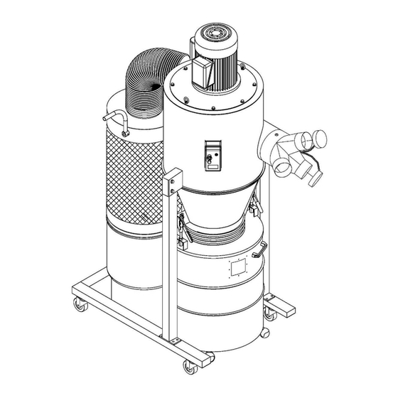
DUST COLLECTOR
MODEL: DC-2100C
Baileigh Industrial, Inc.
P.O. Box 531
Manitowoc, WI 54221-0531
Phone: 920.684.4990
Fax: 920.684.3944
sales@baileighindustrial.com
REPRODUCTION OF THIS MANUAL IN ANY FORM WITHOUT WRITTEN APPROVAL OF BAILEIGH INDUSTRIAL, INC.
IS PROHIBITED. Baileigh Industrial, Inc. does not assume and hereby disclaims any liability for any damage or loss
caused by an omission or error in this Operator's Manual, resulting from accident, negligence, or other occurence.
Rev. 9/2012
© 2012 Baileigh Industrial, Inc.
Advertisement
Table of Contents

Subscribe to Our Youtube Channel
Related Manuals for Baileigh DC-2100C


Summary of Contents for Baileigh DC-2100C
- Page 1 REPRODUCTION OF THIS MANUAL IN ANY FORM WITHOUT WRITTEN APPROVAL OF BAILEIGH INDUSTRIAL, INC. IS PROHIBITED. Baileigh Industrial, Inc. does not assume and hereby disclaims any liability for any damage or loss caused by an omission or error in this Operator’s Manual, resulting from accident, negligence, or other occurence.
-
Page 2: Table Of Contents
Table of Contents THANK YOU & WARRANTY ..................1 INTRODUCTION ......................3 GENERAL NOTES......................3 SAFETY INSTRUCTIONS ....................4 SAFETY PRECAUTIONS ....................6 TECHNICAL SPECIFICATIONS ..................8 TECHNICAL SUPPORT ....................8 INSTALLATION ......................9 Cleaning ........................9 ELECTRICAL ........................ 10 Extension Cord Safety .................... -
Page 3: Thank You & Warranty
THANK YOU & WARRANTY Thank you for your purchase of a machine from Baileigh Industrial. We hope that you find it productive and useful to you for a long time to come. Inspection & Acceptance. Buyer shall inspect all Goods within ten (10) days after receipt thereof. Buyer’s payment shall constitute final acceptance of the Goods and shall act as a waiver of the Buyer’s rights to inspect or... - Page 4 Baileigh Industrial makes every effort to ensure that our posted specifications, images, pricing and product availability are as correct and timely as possible. We apologize for any discrepancies that may occur. Baileigh Industrial reserves the right to make any and all changes deemed necessary in the course of business including but not limited to pricing, product specifications, quantities, and product availability.
-
Page 5: Introduction
After receiving your equipment remove the protective container. Do a complete visual inspection, and if damage is noted, photograph it for insurance claims and contact your carrier at once, requesting inspection. Also contact Baileigh Industrial and inform them of the unexpected occurrence. Temporarily suspend installation. -
Page 6: Safety Instructions
IMPORTANT PLEASE READ THIS OPERATORS MANUAL CAREFULLY It contains important safety information, instructions, and necessary operating procedures. The continual observance of these procedures will help increase your production and extend the life of the equipment. SAFETY INSTRUCTIONS LEARN TO RECOGNIZE SAFETY INFORMATION This is the safety alert symbol. - Page 7 PROTECT EYES Wear safety glasses or suitable eye protection when working on or around machinery. DUST HAZARD Wear appropriate dust mask. Dust created while using machinery can cause cancer, birth defects, and long term respiratory damage. Be aware of the dust hazards associated with all types of materials. DUST PARTICLES AND IGNITION SOURCES DO NOT operate the dust collector in areas where explosion risks are high.
-
Page 8: Safety Precautions
SAFETY PRECAUTIONS Wood working can be dangerous if safe and proper operating procedures are not followed. As with all machinery, there are certain hazards involved with the operation of the product. Using the machine with respect and caution will considerably lessen the possibility of personal injury. However, if normal safety precautions are overlooked or ignored, personal injury to the operator may result. - Page 9 SAFETY PRECAUTIONS (cont.) 11. Check for damaged parts. Before using any tool or machine, carefully check any part that appears damaged. Check for binding of moving parts that may affect proper machine operation. 12. Observe work area conditions. DO NOT use machines or power tools in damp or wet locations.
-
Page 10: Technical Specifications
TECHNICAL SPECIFICATIONS Motor 3 HP (2.23kw) 220V, 60Hz, 1ph Motor Speed 3450 RPM Suction Capacity 2100 CFM 11” H Static Pressure O (279mm H Impeller Size 15” (381mm) 8” x 4” x 3” (203 x 102 x 76mm) Inlet Size Switch Magnetic 54.75”... -
Page 11: Installation
INSTALLATION IMPORTANT: Maintain an adequate working area around the machine for safety. Have the work area well illuminated with proper lighting. Remove scrap and waste materials regularly, and make sure the work area is free from obstructing objects. ... -
Page 12: Electrical
ELECTRICAL CAUTION: HAVE ELECTRICAL UTILITIES CONNECTED TO MACHINE BY A CERTIFIED ELECTRICIAN! Check if the available power supply is the same as listed on the machine nameplate. WARNING: Make sure the grounding wire (green) is properly connected to avoid electric shock. DO NOT switch the position of the green grounding wire if any electrical plug wires are switched during hookup. -
Page 13: Extension Cord Safety
Check with a qualified electrician or service personnel if the grounding instructions are not completely understood, or if in doubt as to whether the tool is properly grounded. Use only 3-wire extension cords that have grounding type plugs and receptacles that accept the tool’s plug. -
Page 14: Contents Of Package
CONTENTS OF PACKAGE... - Page 15 Item Description Qty. Part List No. Main Housing NO.16 Cone NO.33 Base NO.25 Stand NO.22 Canister Filter NO.55 Drum NO.48 Cone Clamp NO.31 Drum Lid NO.40 Inlet Adapter NO.18 Canister Filter Support NO.26 Hose NO.59 Hose NO.39 Hose Clamp 12-1/2” NO.38 Hose Clamp 10-1/2”...
-
Page 16: Hardware Package
HARDWARE PACKAGE Item Description Specification Qty. Part List No. 3/16” x 3/8” Phillips Head Screw NO.17 5/16” x 1/2” Flange Bolt Screw NO.21 Phillips Head Screw M5 x 8 NO.35 1/4” x 1/2” Phillips Head Screw NO.43 1/4” x 3/8” Flange Bolt Screw NO.27 Open Wrench... -
Page 17: Assembly Instruction
ASSEMBLY INSTRUCTION 1. Secure the Base (NO.25) and Base Wheels (NO.24 and 24-1) with 5/16” x 1/2” Flange bolt Screw (No.21). See FIG. 1. 2. Place and secure the Stand (No.22) with 5/16” x 3/4” Flange Bolt Screw (No.8) as FIG. 1. Fig. - Page 18 4. Using an assistant, lift up the main housing (NO.16) then place on the stand (NO.22). Using the Flange bolt Screw 5/16” x 1/2" (NO.21) to tighten together. See (FIG.3). CAUTION: The main housing set is heavy, have at least 2 people work together when lifting.
- Page 19 6. Paste Foam (No.54) as a circle on Canister Filter (No.55) as FIG. 5. Fig. 5 7. Secure the Canister Filter Support (NO.26) and Base (NO.25) with Flange Bolt Screw 5/16” x 3/4” (NO.8). 8. Assemble the Canister Filter (NO.55) on the Main Housing (NO.16) and Canister Filter Support (NO.26), and then tighten with Flange Bolt Screw 5/16”...
- Page 20 9. Secure Hose Clamp (NO.58) on both side of Hose (NO.59), then assemble and tighten Hose (NO.59) on Outlet (NO.16) and Canister filter (NO.55) with Hose clamp (NO.58). 10. Assemble and tighten PE bag (NO.52) on bottom of Canister filter with Bag Clamp (NO.53).
- Page 21 13. Assemble and tighten Hose (NO.39) on Cone (NO.33) and Drum Lid (NO.40) with Hose clamp (NO.38). 14. Pull down the Quick Lever, and then assemble Drum Lid (No.40) and Quick Handle with Long Nut 3/8” (No.41). See (FIG.9) Fig. 9 15.
-
Page 22: Exploded Diagram Sheet 1
EXPLODED DIAGRAM Sheet 1... -
Page 23: Exploded Diagram Sheet 2
EXPLODED DIAGRAM Sheet 2... -
Page 24: Exploded Diagram Sheet 3
EXPLODED DIAGRAM Sheet 3... -
Page 25: Part List
PART LIST Item Description Specification Qty. Motor Bushing 5/16” Spring Washer 5/16” Motor Cord 7 x 7 x 25mm Motor Washer 5/16” x 3/4” Flange Bolt Screw 5/16” Hanger Motor Plate 5/16” x 1” Hex Head Bolt Set Screw 3/8” x 3/4” Impeller 15”... - Page 26 Item Description Specification Qty. Cone Clamp 1/4” x 2-1/2” Hex Head Bolt Cone Quick Handle Phillips Head Screw M5 x 8 3/8” Foam Hose Clamp 12-1/2” 12” Hose Drum Lid Long Nut 3/8” Drum Handle 1/4” x 1/2” Phillips Head Screw Packing Acrylic Board Rivet...
- Page 27 Item Description Specification Qty. Button Head Screw M5 x 16 5/16” 5/16” x 3/4” Set Screw Handle 3/4” 7/8” Sponge Button Head Screw M5 x 6 Bottom Fixing Support Anti-Dust Cover Gear M1.25 x T20 Set Screw M5 x 10 Bearing Support Spindle Flapper Arm...
- Page 28 , WI 54220 UFEK RIVE ANITOWOC : 920. 684. 4990 F : 920. 684. 3944 HONE BAILEIGHINDUSTRIAL BAILEIGH INDUSTRIAL, INC. 1455 S. C , CA 91761 AMPUS VENUE NTARIO : 920. 684. 4990 F : 920. 684. 3944 HONE BAILEIGH INDUSTRIAL LTD. U...
Need help?
Do you have a question about the DC-2100C and is the answer not in the manual?
Questions and answers
My dust collector comes on runs foe 20 seconds then shuts off.
The Baileigh DC-2100C dust collector shutting off after 20 seconds could be caused by an electrical issue, such as incorrect voltage or frequency, or poor grounding. It may also result from improper connection of the power supply or a problem with the timer function on the remote control. Ensure the power matches the machine’s requirements (110V, 60Hz, within ±5% tolerance) and that a certified electrician has connected the machine properly.
This answer is automatically generated